Page 2593 of 3039

Safety Belt System - Safety Belt System - Overview
Description and Operation
Authoring Template
OVERVIEW Published: 11-May-2011
A three point safety belt is fitted to all seating positions. Each safety belt retractor incorporates an emergency locking feature.
The emergency locking retractor incorporates 2 mechanical inertia devices. One inertia device activates if the safety belt is
subjected to a sharp pull. The second inertia device activates if the vehicle is subject to a sudden deceleration or is on a
severe incline.
North American Specification (NAS) safety belt retractors also include an automatic locking feature. The Automatic Locking
Retractor (ALR) is fitted to all passenger seating positions and allows the safety belt to be tensioned to aid the safe fitment
of child or booster seats. For additional information, refer to the Owners Handbook.
NAS vehicles are also fitted with a belt tension sensor on the front passenger seat. The belt tension sensor is incorporated
into the seat belt lower anchorage and is attached to the seat frame by an M10 Torx head bolt. The belt tension sensor forms
part of the SRS (supplemental restraint system) occupancy detection and classification feature.
The center rear safety belt features a mini-buckle lower anchorage. The mini-buckle is disengaged by inserting a suitable tool
into the small aperture on the front face of the housing.
To aid the fitment of child seats, 3 tethers are located on the rear parcel shelf. Each tether is attached to the parcel shelf with
an M10 Torx head bolt.
A safety belt warning indicator is located in the instrument cluster to remind front seat passengers to fasten their safety belts.
The warning indicator will illuminate if the safety belt of an occupied front seat is not fastened.
Refer to: Instrument Cluster (413-01, Description and Operation).
Page 2600 of 3039
Safety Belt System - Front Safety Belt Buckle
Removal and Installation
Removal
NOTE: Removal steps in this procedure may contain installation details. Published: 11-May-2011
1. Refer to: Standard Workshop Practices (100-00 General Information, Description and Operation).
2. Refer to: Front Seat (501-10 Seating, Removal and Installation).
Installation
3. CAUTION: Discard the bolt.
Torque: 35 Nm
1. CAUTION: Make sure that a new bolt is installed. To
install, reverse the removal procedure.
Page 2608 of 3039
Passenger air bag module retaining nuts 6 - 55 Passenger air bag earth lead retaining bolt 9 - 80 Restraints control module (RCM) retaining nuts 10 - 89 Side air curtain module inflator retaining bolts 9 - 80 Side air curtain module tether straps retaining bolts 9 - 80 Side air bag module retaining nuts 7 - 62 Side impact sensor retaining bolt 10 - 89 Front crash sensor retaining bolt 10 - 89 Clock spring retaining screws 5 - 44
Page 2622 of 3039

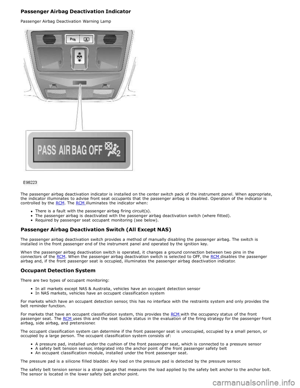
There is a fault with the passenger airbag firing circuit(s).
The passenger airbag is deactivated with the passenger airbag deactivation switch (where fitted).
Required by passenger seat occupant monitoring (see below).
Passenger Airbag Deactivation Switch (All Except NAS)
The passenger airbag deactivation switch provides a method of manually disabling the passenger airbag. The switch is
installed in the front passenger end of the instrument panel and operated by the ignition key.
When the passenger airbag deactivation switch is operated, it changes a ground connection between two pins in the
connectors of the RCM. When the passenger airbag deactivation switch is selected to OFF, the RCM disables the passenger airbag and, if the front passenger seat is occupied, illuminates the passenger airbag deactivation indicator.
Occupant Detection System
There are two types of occupant monitoring:
In all markets except NAS & Australia, vehicles have an occupant detection sensor
In NAS markets, vehicles have an occupant classification system
For markets which have an occupant detection sensor, this has no interface with the restraints system and only provides the
belt reminder function.
For markets that have an occupant classification system, this provides the RCM with the occupancy status of the front passenger seat. The RCM uses this and the seat buckle status in the evaluation of the firing strategy for the passenger front airbag, side airbag, and pretensioner.
The occupant classification system can determine if the front passenger seat is unoccupied, occupied by a small person, or
occupied by a large person. The occupant classification system consists of:
A pressure pad, installed under the cushion of the front passenger seat, which is connected to a pressure sensor
A safety belt tension sensor, integrated into the anchor point of the front passenger safety belt
An occupant classification module, installed under the front passenger seat.
The pressure pad is a silicone filled bladder. Any load on the pressure pad is detected by the pressure sensor.
The safety belt tension sensor is a strain gauge that measures the load applied by the safety belt anchor to the anchor bolt.
The sensor is located in the lower safety belt anchor point.
Page 2721 of 3039
1
Between Panels - Bolted 2
Panel Edge Bolted 3
Between Panels - spot welded 4
Panel edges - spot welded 5
Between panels - bonded 6
Panel edges - bonded 7
Clinch joints - type A 8
Clinch joints - type B 9
Clinch joints - type C 10
Gaps between panels - type A 11
Gaps between panels - type B 12
Lap joint Body Sealing Materials
Page 2726 of 3039

metal surfaces are bolted together always interpose a suitable interface material such as weldable zinc rich primer, extruded
strip, or zinc tape.
Steam Cleaning
Due to the high pressure/temperature generated by steam cleaning equipment, there is a risk that certain adhesives and
corrosion prevention material may become softened or liquified.
Take care not to allow the steam jet to dwell on one area, and keep the nozzle at least 300mm from the panel surface.
CAUTION: Do not remove wax or lacquer from underbody areas during repairs.
Inspection During Maintenance Servicing
It is a requirement of the corrosion warranty that the vehicle is inspected for corrosion by a Jaguar Authorised Repairer during a
routine service, to ensure that the factory-applied protection remains effective.
Rectify any bodywork damage or evidence of corrosion found during inspection as soon as is practicable, both to minimise the
extent of the damage and to ensure the long term effectiveness of the factory-applied corrosion prevention treatment.
Underbody Protection Repairs
Whenever body repairs have been carried out, ensure that full sealing and corrosion protection treatments are reinstated. This
applies both to the damaged areas and also to areas where protection has been indirectly impaired, as a result either of
accident damage or repair operations.
Remove corrosion protection from the damaged areas before straightening or panel beating. This applies in particular to panels
coated with wax, PVC underbody sealer, sound deadening pads etc.
CAUTION: Do not use oxy-acetylene to remove corrosion prevention material. Large volumes of fumes and gases are
liberated by these materials when they burn.
The most common method of removal is by means of a hot air blower with an integral scraper. High temperatures can be
generated with this equipment which may cause fumes. Take care during its use.
Structural Adhesive
CAUTION: When separating a joint with metal to metal adhesive, it is important to avoid distortion. Heat gradually until
the bond weakens sufficiently to permit panel separation - do not apply excessive heat.
NOTE: When spot welding through metal to metal adhesive, take particular care to adjust the equipment setting to
ensure a suitable weld.
Metal to metal adhesive is applied to critical joint areas during factory assembly. The material used is a high temperature,
heat cured, nitrile phenolic which serves to bond two metal surfaces and also to seal the joint against ingress of dust,
moisture and fumes. This material is not suitable for service use and, during repair, should be substituted by an approved
structural adhesive. For panel specific information and to identify the areas of structural adhesive application in repair, refer to
the relevant sheet metal removal and installation procedure.
Expanding Foam Acoustic Seals
Expanding foam acoustic seals are used in various closed-sections of the body to improve vehicle refinement. The seals are
installed during the vehicle body manufacture and expand during the paint process up to ten times original size, thus locking
them into position. They are located such that they prevent noise accentuation along a section and reflect air borne noise
away from the cabin.
The seals have spilt functionality depending on location. The seals located at the base of the body pillars have a primary
function of preventing water ingress when wading. Their secondary function is to prevent noise and dust ingress.
The seal around the fuel filler has a primary function of preventing both fuel and water ingress. With a secondary function of
preventing noise and dust ingress.
The remaining seals primary function is to prevent noise accentuation along a section and reflect air borne noise away from the
cabin.
Another advantage of the seals is that they marginally increase the overall stiffness of the body and its structural performance
in case of a crash.
The seals are manufactured from an expandible polymer.
Replacing Expanding Foam Acoustic Seals
As paint oven temperatures used in a repair workshop are significantly lower than those that are used during manufacture of
the vehicle, (the temperatures are not sufficient to expand the foam), a different process is required to replicate the foam in
repair.
Page 2737 of 3039
Published: 11-May-2011
Body Repairs - Vehicle Specific Information and Tolerance Checks - Body and
Frame
Description and Operation
Front End Body Dimensions
NOTES:
All dimensions shown are in millimetres (mm).
Dimensions shown to holes, are always taken from/to the hole centre. They are also always to the body panel surface,
not to the top of bolts or components.
Page 2782 of 3039
8. NOTE: If the front fender lower mounting is
undamaged it should be retained for reuse.
Remove the front fender lower mounting retaining bolt.
9. drill.
NOTE: Use a belt sander where there is no access to
Drill out the spot welds.
10. Separate the joints and remove the old panel.
Installation
1. Prepare the old and new panel joint surfaces.
2. Offer up the new panel and clamp into position. Check alignment, if
correct, proceed to next step, if not rectify and recheck before
proceeding.
3. NOTE: Spot welds must be installed 5mm away from the
originals and in the same quantities, whenever this is
possible. Where this is not possible spot welds should be
installed adjacent to the original.
Spot weld.