2010 JAGUAR XFR sport mode
[x] Cancel search: sport modePage 1848 of 3039
information from other systems:
ABS (anti-lock brake system) module - Road speed signal
TCM (transmission control module) - Reverse gear engaged signal
Trailer module - Trailer attached to vehicle
The module also outputs messages on the medium speed CAN bus which are received by the integrated audio module. The integrated audio module processes these messages and converts them into Media Orientated System Transport (MOST) signals
which are passed to the audio system power amplifier. These signals are then used by the power amplifier to emit the
applicable warning tones from the front or rear audio speakers when an object is detected by the front or rear parking aid
sensors. A warning tone can also be emitted to alert the driver to a fault in the parking aid system.
The control module has a diagnostic connection via the medium speed CAN bus to enable faults to be retrieved using the
Jaguar approved diagnostic equipment. Additionally an on-board diagnostic routine within the control module constantly
monitors the system and alerts the driver to a system fault by emitting a 3 second continuous tone through the rear audio
system speakers when the ignition is switched on. If front parking aid sensors are fitted, the control switch LED will also flash
6 times.
Parking Aid Sensors
Four ultrasonic sensors are located in the front (if fitted) and rear bumpers.
Each sensor has a three pin connector which mates with a bumper harness, which in turn is connected to the main body
harness. Three pins provide for power supply, ground and signal lines to and from the parking aid module.
The parking aid module controls the operation of each sensor using a digital output on the signal line. The module controls the
sensor in one of two modes; combined transmitter and receiver mode or receiver mode only.
Parking Aid Switch
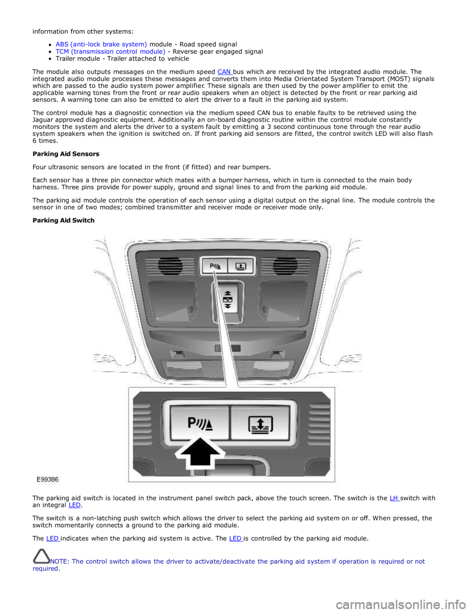
The parking aid switch is located in the instrument panel switch pack, above the touch screen. The switch is the LH switch with an integral LED.
The switch is a non-latching push switch which allows the driver to select the parking aid system on or off. When pressed, the
switch momentarily connects a ground to the parking aid module.
The LED indicates when the parking aid system is active. The LED is controlled by the parking aid module.
NOTE: The control switch allows the driver to activate/deactivate the parking aid system if operation is required or not
required.
Page 1867 of 3039
procedure.
NOTE: Under no circumstances should the battery be disconnected with the engine running because under these
conditions the generator can give a very high output voltage. This high transient voltage will damage the electronic
components in the vehicle. Loose or incomplete battery connections may also cause high transient voltage.
3. HEALTH AND SAFETY PRECAUTIONS
WARNINGS:
BATTERY CELLS CONTAIN SULPHURIC ACID AND EXPLOSIVE MIXTURES OF HYDROGEN AND OXYGEN GASES. IT IS
THEREFORE ESSENTIAL THAT THE FOLLOWING SAFETY PRECAUTIONS ARE OBSERVED.
Batteries emit highly explosive hydrogen at all times, particularly during charging. To prevent any potential form of
ignition occurring when working in the vicinity of a battery:
Do not smoke when working near batteries.
Avoid sparks, short circuits or other sources of ignition in the battery vicinity.
Switch off current before making or breaking electrical connections.
Ensure battery charging area is well ventilated.
Ensure the charger is switched off when: a) connecting to a battery; b) disconnecting from the battery.
Always disconnect the ground cable from the battery terminal first and reconnect it last.
Batteries contain poisonous and highly corrosive acid. To prevent personal injury, or damage to clothing or the vehicle,
the following working practices should be followed when topping up, checking electrolyte specific gravity, removal, refitting or
carrying batteries:
Always wear suitable protective clothing (an apron or similar), safety glasses, a face mask and suitable gloves.
If acid is spilled or splashed onto clothing or the body, it must be neutralized immediately and then rinsed with clean
water. A solution of baking soda or household ammonia and water may be used as a neutralizer.
In the event of contact with the skin, drench the affected area with water. In the case of contact with the eyes, bathe
the affected area with cool clean water for approximately 15 minutes and seek urgent medical attention.
If battery acid is spilled or splashed on any surface of a vehicle, it should be neutralized and rinsed with clean water.
Heat is generated when acid is mixed with water. If it becomes necessary to prepare electrolyte of a desired specific
gravity, SLOWLY pour the concentrated acid into water (not water into acid), adding small amounts of acid while
stirring. Allow the electrolyte to cool if noticeable heat develops. With the exception of lead or lead-lined containers,
always use non-metallic receptacles or funnels. Do not store acid in excessively warm locations or in direct sunlight.
Due to their hazardous contents, the disposal of batteries is strictly controlled. When a battery is scrapped, ensure it is
disposed of safely, complying with local environmental regulations. If in doubt, contact your local authority for advice on
disposal facilities.
4. BATTERY CARE REQUIREMENTS
4.1 RECEIPT OF A NEW VEHICLE
Within 24 hours of receipt of a new vehicle, a battery condition check must be carried out in accordance with the battery test
process utilizing a JLR approved tester as outlined in the Equipment section (Section 5) of this procedure.
NOTE: The Midtronics code from the tester must be recorded on the form.
Any actions must be carried out in accordance with the table shown in the Determining Battery Condition section (Section 6)
of this procedure. The details must be recorded on the New Vehicle Storage Form which is part of the new vehicle storage
document.
For additional information, refer to: New Vehicle Storage Form (100-11 Vehicle Transportation Aids and Vehicle Storage, Description and Operation).
4.2 NEW VEHICLE STORAGE
If the vehicle is to be stored the transit relays MUST be refitted and / or the vehicle put into transport mode.
Transit relay removal / vehicle placed in normal mode should only be completed a maximum of 72 hours prior to handover to
customer
For vehicles without either a transit mode or transit relay the battery negative cable must be DISCONNECTED from the battery.
The battery must be tested and/or re-charged every 30 days and MUST be re-charged after every 90 day period.
NOTE: The Midtronics code from the tester must be recorded on the form. www.JagDocs.com
Page 1868 of 3039
Any actions must be carried out in accordance with the table shown in the Determining Battery Condition section (Section 6)
of this procedure. The details must be recorded on the New Vehicle Storage Form which is part of the new vehicle storage
document.
For additional information, refer to: New Vehicle Storage Form (100-11 Vehicle Transportation Aids and Vehicle Storage, Description and Operation).
4.3 PDI / DELIVERY TO CUSTOMER
Before the vehicle is handed over to the customer and as part of the PDI, the condition of the battery needs to be confirmed.
The battery condition must be checked in accordance with the battery test process utilizing a JLR approved tester as outlined
in the Equipment section (Section 5) of this procedure.
NOTE: The Midtronics code from the tester must be recorded on the form.
Any actions must be carried out in accordance with the table shown in the Determining Battery Condition section (Section 6)
of this procedure. The details must be recorded on the New Vehicle Storage Form which is part of the new vehicle storage
document.
For additional information, refer to: New Vehicle Storage Form (100-11 Vehicle Transportation Aids and Vehicle Storage, Description and Operation).
4.4 REPLACEMENT BATTERIES FOR SERVICE
All service replacement batteries must have the battery condition checked within 24 hours of receipt and controlled on a ‘First
In First Out’ basis to ensure batteries are not allowed to age unnecessarily.
For batteries in storage and not yet fitted to a vehicle, they must be stored in a dry environment, not in direct sunlight or
under any direct heat source. Any batteries exhibiting any forms of damage or corrosion must not be fitted to any vehicle. Any
batteries which are dropped must be scrapped, this applies even if no external damage is apparent.
The battery condition must be checked every 30 days in accordance with the battery test process utilizing a JLR approved
tester as outlined in the Equipment section (Section 5) of this procedure.
Any actions must be carried out in accordance with the table shown in the Determining Battery Condition section (Section 6)
of this procedure.The details must be recorded on the New Vehicle Storage Form which is part of the new vehicle storage
document.
For additional information, refer to: New Vehicle Storage Form (100-11 Vehicle Transportation Aids and Vehicle Storage, Description and Operation).
4.5 BATTERY MAINTENANCE
Any battery whether it is in a vehicle or a replacement part must be tested and/or re-charged every 30 days and MUST be
re-charged after every 90 day period.
4.6 BATTERY TEST PROCESS
It is recommended that this test is conducted at least 24 hours after the vehicle engine has been run or the battery charged to
avoid the need of surface charge removal. If time constraints make this unacceptable then the surface charge must be
removed.
Surface Charge Removal
A vehicle which has had its battery charged or been driven in a 24 hour period before the test, must have its surface charge
removed.
Turn on the ignition (power mode 6) but do not start the vehicle
Switch on the headlamps on high beam for a minimum 3 minutes
Switch off the headlamps
Wait a minimum of 5 minutes before recording test results for any battery measurements
Battery Test
The battery may be tested either on a bench or on the vehicle.
The battery condition must be checked in accordance with the battery test process utilizing a JLR approved tester as outlined
in the Equipment section (Section 5) of this procedure.
NOTE: The Midtronics code from the tester must be recorded on the form.
Any actions must be carried out in accordance with the table shown in the Determining Battery Condition section (Section 6)
of this procedure. The details must be recorded on the New Vehicle Storage Form which is part of the new vehicle storage
document.
For additional information, refer to: New Vehicle Storage Form (100-11 Vehicle Transportation Aids and Vehicle Storage, Description and Operation).
CAUTION: DO NOT connect the tester to any other circuit or chassis point other than the battery negative terminal.
Page 1869 of 3039
5. EQUIPMENT
All equipment used must be functionally capable of meeting the compliance requirements. Please refer to the approved
equipment document (JLR 000015).
In the case of batteries fitted to a new vehicle at the dealership, battery condition should be measured using the appropriate
hand-held Midtronics tester as follows:
Battery Type Battery Tester Battery Tester Jaguar Land Rover AGM & Flooded Midtronics EXP1080, GRX 3080 Midtronics EXP1080, GRX 3080 The test results must be recorded on the New Vehicle Storage Form which is part of the new vehicle storage document.
For additional information, refer to: New Vehicle Storage Form (100-11 Vehicle Transportation Aids and Vehicle Storage, Description and Operation).
NOTE: All equipment must be calibrated
6 DETERMINING BATTERY CONDITION
TESTER RESULTS ACTION GOOD BATTERY Return to service. GOOD RE-CHARGE Fully charge battery and return to service. CHARGE AND RE-TEST Fully charge battery. Remove surface charge. Re-test battery. If same result replace battery. REPLACE BATTERY OR BAD
CELL BATTERY Verify surface charge removed. Disconnect battery from vehicle and re-test. If result repeats after
surface charge removal, replace battery. DO NOT RECHARGE. UNABLE TO DO TEST Disconnect battery from vehicle and re-test. 7 BATTERY CHARGING
It is essential that a suitably ventilated defined area exists in each dealership / retailer for battery charging.
CAUTION: It is very important that when charging batteries using the traction charger or other stand-alone chargers that
the charger is set for the correct type of battery before charging commences. If the wrong switch is selected the result would
be a battery that is not charged fully and / or overheating can occur. Follow the manufacturers operating instructions.
Batteries MUST BE tested and if necessary charged every 30 days and charged after 90 days irrespective of any test. It is
recommended that dealers / retailers always have fully charged batteries ready for use.
CAUTION: Do not charge AGM batteries with voltages over 14.8 Volts as this will damage the battery.
A designated controlled area must be allocated for scrap batteries and clearly controlled as such.
To bring a discharged but serviceable battery back to a fully charged condition proceed as follows:
Check and if necessary top-up the battery electrolyte level. (Flooded maintainable batteries only)
Charge the battery using a JLR approved charger as detailed in the approved equipment document following the
manufacturers operating instructions.
NOTE: When using the Midtronics Diagnostic Charger, automatic mode must always be used. After charging and analysis,
the charger may display ‘Top-Off Charging’, Hit STOP To End. Do not stop charging until the current falls to 5A or less,
otherwise the battery will not be fully charged.
Following charging, a post charge battery condition test must be carried out in accordance with the table shown in the
Determining Battery Condition section (Section 6) of this procedure.
NOTE: The Midtronics code from the tester must be recorded on the form.
Any actions must be carried out in accordance with the table shown in the Determining Battery Condition section (Section 6)
of this procedure. The details must be recorded on the New Vehicle Storage Form which is part of the new vehicle storage
document.
For additional information, refer to: New Vehicle Storage Form (100-11 Vehicle Transportation Aids and Vehicle Storage, Description and Operation).
8 BATTERY REPLACEMENT
If it is determined that a battery requires replacement, always refer to the appropriate section of the workshop manual for
instructions on removing and installing the battery from the vehicle.
On in service vehicles fitted with a Battery Monitoring System (BMS), the BMS control module must be reset following the
installation of a new battery. The BMS control module reset procedure must be performed using an approved diagnostic
Page 1872 of 3039
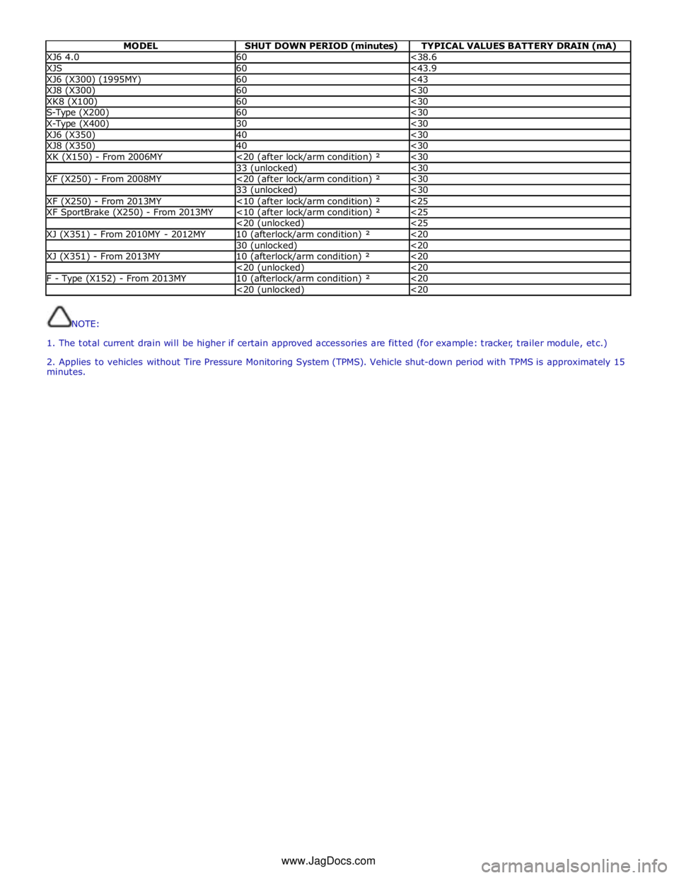
MODEL SHUT DOWN PERIOD (minutes) TYPICAL VALUES BATTERY DRAIN (mA) XJ6 4.0 60 <38.6 XJS 60 <43.9 XJ6 (X300) (1995MY) 60 <43 XJ8 (X300) 60 <30 XK8 (X100) 60 <30 S-Type (X200) 60 <30 X-Type (X400) 30 <30 XJ6 (X350) 40 <30 XJ8 (X350) 40 <30 XK (X150) - From 2006MY <20 (after lock/arm condition) ² <30 33 (unlocked) <30 XF (X250) - From 2008MY <20 (after lock/arm condition) ² <30 33 (unlocked) <30 XF (X250) - From 2013MY <10 (after lock/arm condition) ² <25 XF SportBrake (X250) - From 2013MY <10 (after lock/arm condition) ² <25 <20 (unlocked) <25 XJ (X351) - From 2010MY - 2012MY 10 (afterlock/arm condition) ² <20 30 (unlocked) <20 XJ (X351) - From 2013MY 10 (afterlock/arm condition) ² <20 <20 (unlocked) <20 F - Type (X152) - From 2013MY 10 (afterlock/arm condition) ² <20 <20 (unlocked) <20
NOTE:
1. The total current drain will be higher if certain approved accessories are fitted (for example: tracker, trailer module, etc.)
2. Applies to vehicles without Tire Pressure Monitoring System (TPMS). Vehicle shut-down period with TPMS is approximately 15
minutes.
www.JagDocs.com
Page 1968 of 3039
System Operation
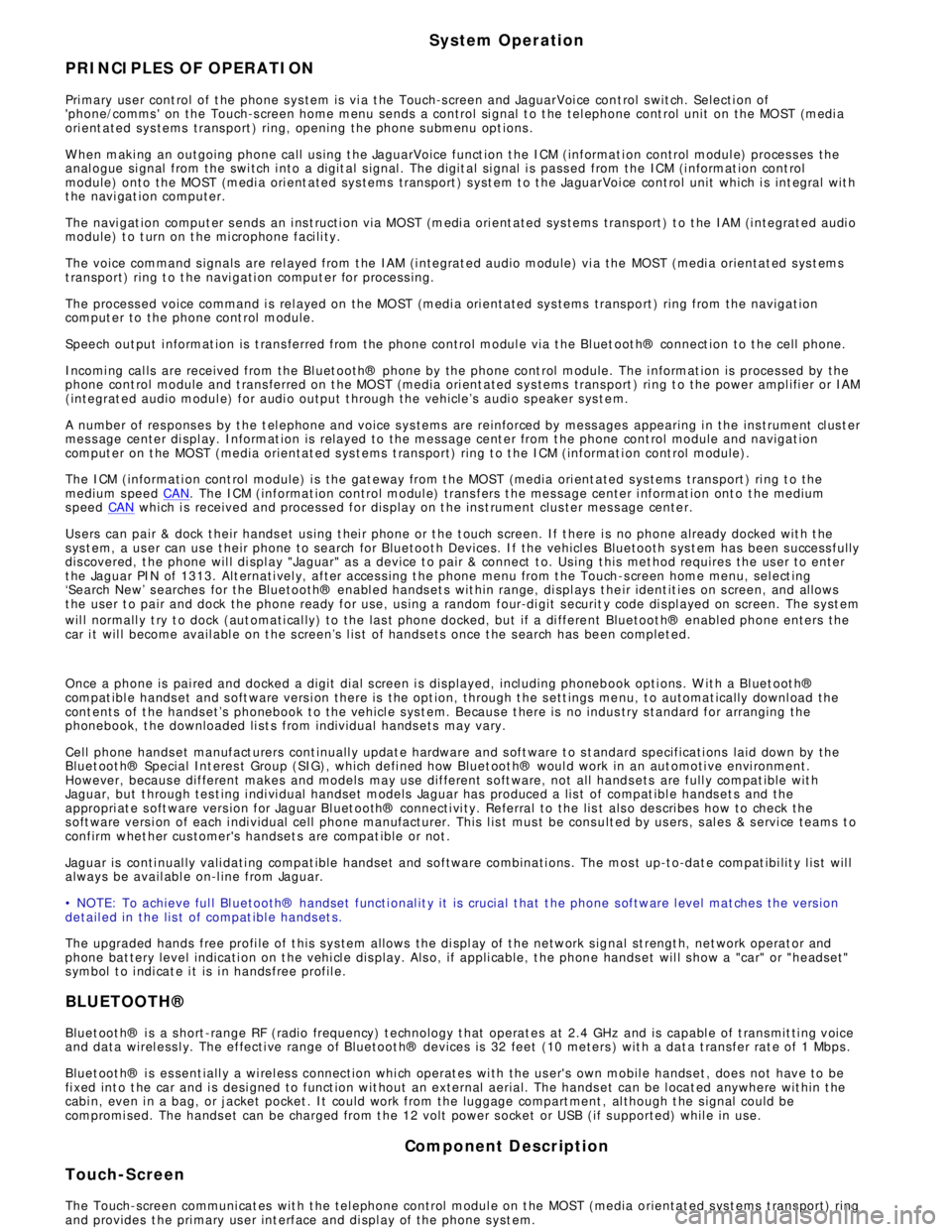
PRINCIPLES OF OPERATION
Pri mary us er cont rol of t he phone s ys tem is vi a t he Touch-s creen and JaguarVoi ce cont rol s wit ch. Selecti on of
'phone/comms ' on the Touch-s creen home menu sends a control si gnal t o t he tel ephone cont rol unit on the MO ST (medi a
ori ent ated sys tems trans port ) ring, opening the phone s ubmenu opt ions .
W hen maki ng an outgoing phone call us ing t he JaguarVoice funct ion t he ICM (informat i on control modul e) proces s es the
anal ogue si gnal from the swi tch i nto a digit al s ignal . The digit al si gnal i s pass ed from the ICM (i nformat ion cont rol
module) onto the MO ST (medi a ori ent ated sys tems trans port ) s yst em t o t he JaguarVoi ce cont rol unit which i s int egral wit h
t he navi gat ion computer.
The navi gat ion comput er s ends an i ns t ructi on via MO ST (medi a ori ent ated sys tems trans port ) t o t he IAM (i ntegrat ed audi o
module) t o t urn on t he mi crophone faci li ty.
The voice command s ignals are rel ayed from t he IAM (i ntegrat ed audio module) vi a the MOST (medi a orientat ed s ys t ems
t ransport) ring t o t he navi gati on comput er for process ing.
The process ed voice command i s rel ayed on the MO ST (medi a ori ent ated sys tems trans port ) ring from the navigat ion
comput er to the phone cont rol module.
Speech out put i nformat ion is t rans ferred from the phone control modul e via t he Bl uet oot h® connect ion to t he cell phone.
Incomi ng cal ls are received from the Bl uet ooth® phone by the phone cont rol module. The i nformat ion is proces sed by the
phone cont rol module and t rans ferred on t he MOST (media ori ent ated s ys tems trans port ) ri ng t o the power ampl ifi er or IAM
(integrat ed audio modul e) for audi o output t hrough the vehicle’s audi o s peaker s ys t e m.
A number of res pons es by t he t el ephone and voice s ys tems are reinforced by mess ages appearing i n the ins trument cl us t er
mes s age center di spl ay. Informat ion is relayed to the mess age cent er from t he phone cont rol module and navigat ion
comput er on t he MOST (media orientat ed s ys t ems t rans port) ring t o t he ICM (informat ion cont rol module).
The ICM (informati on cont rol module) i s the gat eway from t he MOST (media ori ent ated s ys tems trans port ) ri ng t o the
medium s peed CAN. The ICM (informat ion control modul e) trans fers t he mes sage center i nformat ion ont o t he medium
s peed CAN which i s received and process ed for dis play on t he ins t rument clus ter mes s age cente r.
Us ers can pair & dock t heir hands et us ing t hei r phone or t he t ouch s creen. If t here i s no phone already docked wit h t he
s ys t em, a us er can us e t heir phone to search for Bluetoot h Devices. If the vehicl es Bluetooth s ys t em has been s uccess fully
dis covered, t he phone wil l di spl ay "Jaguar" as a device t o pair & connect t o. Us ing t his met hod requires the us er t o enter
t he Jaguar PIN of 1313. Alt ernati vel y, after acces s ing t he phone menu from t he Touch-s creen home menu, sel ect ing
‘Search New’ s earches for the Bluetooth® enabl ed hands et s wit hin range, di spl ays t he ir ident it ies on s creen, and al lows
t he user t o pair and dock the phone ready for use, us ing a random four-di git s ecurit y code di s pl ayed on screen. The s yst em
wil l normall y t ry t o dock (aut omati cal ly) to the las t phone docked, but if a di ffere nt Bluetoot h® enabled phone enters the
car i t wil l become avail abl e on t he s creen’s l is t of hands ets once t he s earch has be en complet ed.
Once a phone is pai red and docked a digit di al s creen i s dis played, incl uding phonebook opti ons . W it h a Bl uet oot h®
compat ibl e hands et and s oft ware vers i on there is the opt ion, through t he s ett ings me nu, t o automat ically downl oad the
cont ents of t he hands et’s phonebook t o the vehicl e s ys t em. Becaus e t here is no indus try s tandard for arranging the
phonebook, t he downloaded li st s from individual hands ets may vary.
Cell phone hands et manufact urers cont inuall y updat e hardware and s oft ware t o s t andard specificati ons laid down by the
Bluet oot h® Special Int eres t Group (SIG), which defi ned how Bluet oot h® woul d work in an aut omoti ve envi ronment.
However, becaus e different makes and models may use different s oft ware, not all hands ets are full y compat ible wit h
Jaguar, but t hrough tes t ing i ndi vi dual handset models Jaguar has produced a lis t of compat ibl e hands et s and the
appropri at e s oft ware vers ion for Jaguar Bl uet ooth® connecti vi ty. Referral to the lis t als o des cri bes how to check the
s oft ware vers i on of each i ndi vidual cell phone manufacturer. This l is t mus t be cons ult ed by us ers , s al es & s ervi ce teams t o
confirm whet her cus tomer's handset s are compat ible or not .
Jaguar is conti nual ly vali dati ng compat ible hands et and software combinati ons . The mos t up-t o-dat e compat ibi lit y l is t wil l
always be avail abl e on-l ine from Jaguar.
• NOTE: To achieve ful l Bl uetooth® hands et functi onal it y it is crucial t hat t he phone s oftware l evel mat ches t he vers ion
detail ed in the lis t of compat ibl e hands et s.
The upgraded hands free profi le of t his s ys tem allows the di spl ay of t he network s ignal st rengt h, net work operat or and
phone bat tery level indicati on on t he vehi cl e dis play. Als o, if appli cable, t he phone hands et wil l s how a "car" or "heads et"
s ymbol t o i ndi cat e i t is i n hands free profil e.
BLUETOOTH®
Bluet oot h® i s a s hort -range RF (radio frequency) t echnology t hat operat es at 2.4 GHz and is capabl e of t rans mit ti ng voice
and data wirel ess l y. The effecti ve range of Bluetoot h® devices is 32 feet (10 meters ) wit h a dat a t ransfer rat e of 1 Mbps .
Bluet oot h® i s es sent iall y a wi rel es s connect ion whi ch operat es wi th the us er's own mobil e hands et , does not have to be
fi xed int o t he car and i s desi gned to funct ion wit hout an external aerial. The hands et can be l ocat ed anywhere wit hin t he
cabi n, even i n a bag, or jacket pocket . It could work from the luggage compart ment , al though t he s ignal could be
compromi sed. The hands et can be charged from t he 12 volt power s ocket or USB (if s upported) whil e in use.
Component Description
Touch-Screen
The Touch-screen communi cat es wit h t he tel ephone control modul e on t he MOST (media orientat ed s ys t ems t rans port) ring
and provides t he pri mary us er int erface and di spl ay of the phone s yst em.
Page 2033 of 3039
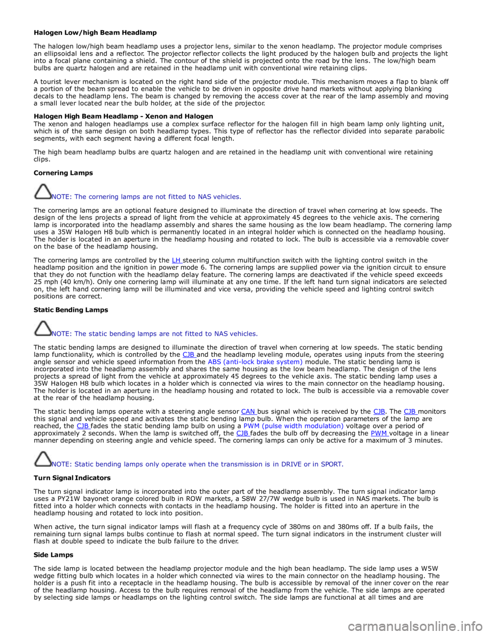
Halogen Low/high Beam Headlamp
The halogen low/high beam headlamp uses a projector lens, similar to the xenon headlamp. The projector module comprises
an ellipsoidal lens and a reflector. The projector reflector collects the light produced by the halogen bulb and projects the light
into a focal plane containing a shield. The contour of the shield is projected onto the road by the lens. The low/high beam
bulbs are quartz halogen and are retained in the headlamp unit with conventional wire retaining clips.
A tourist lever mechanism is located on the right hand side of the projector module. This mechanism moves a flap to blank off
a portion of the beam spread to enable the vehicle to be driven in opposite drive hand markets without applying blanking
decals to the headlamp lens. The beam is changed by removing the access cover at the rear of the lamp assembly and moving
a small lever located near the bulb holder, at the side of the projector.
Halogen High Beam Headlamp - Xenon and Halogen
The xenon and halogen headlamps use a complex surface reflector for the halogen fill in high beam lamp only lighting unit,
which is of the same design on both headlamp types. This type of reflector has the reflector divided into separate parabolic
segments, with each segment having a different focal length.
The high beam headlamp bulbs are quartz halogen and are retained in the headlamp unit with conventional wire retaining
clips.
Cornering Lamps
NOTE: The cornering lamps are not fitted to NAS vehicles.
The cornering lamps are an optional feature designed to illuminate the direction of travel when cornering at low speeds. The
design of the lens projects a spread of light from the vehicle at approximately 45 degrees to the vehicle axis. The cornering
lamp is incorporated into the headlamp assembly and shares the same housing as the low beam headlamp. The cornering lamp
uses a 35W Halogen H8 bulb which is permanently located in an integral holder which is connected on the headlamp housing.
The holder is located in an aperture in the headlamp housing and rotated to lock. The bulb is accessible via a removable cover
on the base of the headlamp housing.
The cornering lamps are controlled by the LH steering column multifunction switch with the lighting control switch in the headlamp position and the ignition in power mode 6. The cornering lamps are supplied power via the ignition circuit to ensure
that they do not function with the headlamp delay feature. The cornering lamps are deactivated if the vehicle speed exceeds
25 mph (40 km/h). Only one cornering lamp will illuminate at any one time. If the left hand turn signal indicators are selected
on, the left hand cornering lamp will be illuminated and vice versa, providing the vehicle speed and lighting control switch
positions are correct.
Static Bending Lamps
NOTE: The static bending lamps are not fitted to NAS vehicles.
The static bending lamps are designed to illuminate the direction of travel when cornering at low speeds. The static bending
lamp functionality, which is controlled by the CJB and the headlamp leveling module, operates using inputs from the steering angle sensor and vehicle speed information from the ABS (anti-lock brake system) module. The static bending lamp is
incorporated into the headlamp assembly and shares the same housing as the low beam headlamp. The design of the lens
projects a spread of light from the vehicle at approximately 45 degrees to the vehicle axis. The static bending lamp uses a
35W Halogen H8 bulb which locates in a holder which is connected via wires to the main connector on the headlamp housing.
The holder is located in an aperture in the headlamp housing and rotated to lock. The bulb is accessible via a removable cover
at the rear of the headlamp housing.
The static bending lamps operate with a steering angle sensor CAN bus signal which is received by the CJB. The CJB monitors this signal and vehicle speed and activates the static bending lamp bulb. When the operation parameters of the lamp are
reached, the CJB fades the static bending lamp bulb on using a PWM (pulse width modulation) voltage over a period of approximately 2 seconds. When the lamp is switched off, the CJB fades the bulb off by decreasing the PWM voltage in a linear manner depending on steering angle and vehicle speed. The cornering lamps can only be active for a maximum of 3 minutes.
NOTE: Static bending lamps only operate when the transmission is in DRIVE or in SPORT.
Turn Signal Indicators
The turn signal indicator lamp is incorporated into the outer part of the headlamp assembly. The turn signal indicator lamp
uses a PY21W bayonet orange colored bulb in ROW markets, a S8W 27/7W wedge bulb is used in NAS markets. The bulb is
fitted into a holder which connects with contacts in the headlamp housing. The holder is fitted into an aperture in the
headlamp housing and rotated to lock into position.
When active, the turn signal indicator lamps will flash at a frequency cycle of 380ms on and 380ms off. If a bulb fails, the
remaining turn signal lamps bulbs continue to flash at normal speed. The turn signal indicators in the instrument cluster will
flash at double speed to indicate the bulb failure to the driver.
Side Lamps
The side lamp is located between the headlamp projector module and the high bean headlamp. The side lamp uses a W5W
wedge fitting bulb which locates in a holder which connected via wires to the main connector on the headlamp housing. The
holder is a push fit into a receptacle in the headlamp housing. The bulb is accessible by removal of the inner cover on the rear
of the headlamp housing. Access to the bulb requires removal of the headlamp from the vehicle. The side lamps are operated
by selecting side lamps or headlamps on the lighting control switch. The side lamps are functional at all times and are
Page 2067 of 3039
Published: 11-May-2011
Module Communications Network - Communications Network - Overview
Description and Operation
OVERVIEW
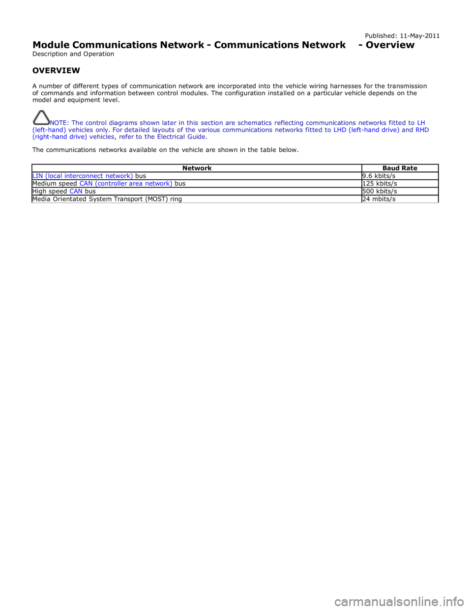
A number of different types of communication network are incorporated into the vehicle wiring harnesses for the transmission
of commands and information between control modules. The configuration installed on a particular vehicle depends on the
model and equipment level.
NOTE: The control diagrams shown later in this section are schematics reflecting communications networks fitted to LH
(left-hand) vehicles only. For detailed layouts of the various communications networks fitted to LHD (left-hand drive) and RHD
(right-hand drive) vehicles, refer to the Electrical Guide.
The communications networks available on the vehicle are shown in the table below.
Network Baud Rate LIN (local interconnect network) bus 9.6 kbits/s Medium speed CAN (controller area network) bus 125 kbits/s High speed CAN bus 500 kbits/s Media Orientated System Transport (MOST) ring 24 mbits/s