2010 JAGUAR XFR spare tire
[x] Cancel search: spare tirePage 467 of 3039

TEST CONDITIONS DETAILS/RESULTS/ACTIONS I1: C1D1912 VERIFY EXTERNAL RECEIVER DATA LINE CIRCUIT SHORT TO POWER 1 Ignition off. 2 Disconnect the Tire Pressure Monitoring System Receiver electrical connector, C3MC45. 3 Measure the resistance between C3MC45, harness side Battery Pin 1 Positive terminal Is the resistance less than 5 Ohms?
Yes
GO to I2. No
GO to I3. I2: C1D1912 CHECK THE EXTERNAL RECEIVER DATA LINE CIRCUIT FOR SHORT CIRCUIT TO POWER 1 Disconnect the Tire Pressure Monitoring System Control Module electrical connector, C3MC39B. 2 Measure the resistance between C3MC45, harness side Battery Pin 1 Positive terminal Is the resistance less than 5 Ohms?
Yes
REPAIR the short circuit in wiring harness.
No
GO to I4. I3: C1D1912 CHECK THE TIRE PRESSURE MONITORING SYSTEM EXTERNAL RECEIVER FOR SHORT CIRCUIT TO
POWER 1 Reconnect the Tire Pressure Monitoring System Receiver electrical connector, C3MC45. 2 Using manufacturer approved diagnostic system run On Demand Self Test (0x0202). Is the DTC C1D1912 set?
Yes
Replace Tire Pressure Monitoring Receiver.
No
Investigate possible cause of intermittent failure. I4: C1D1912 CHECK THE TIRE PRESSURE MONITORING SYSTEM CONTROL MODULE FOR SHORT CIRCUIT TO POWER 1 Reconnect the Tire Pressure Monitoring System Control Module electrical connector, C3MC39B. 2 Reconnect the Tire Pressure Monitoring System Receiver electrical connector, C3MC45. 3 Using manufacturer approved diagnostic system run On Demand Self Test (0x0202). Is the DTC C1D1912 set?
Yes
Replace Tire Pressure Monitoring System Control Module.
No
Investigate possible cause of intermittent failure.
PINPOINT TEST J : C1D1987 TIRE PRESSURE MONITORING SYSTEM EXTERNAL RECEIVER DATA LINE
MISSING MESSAGE TEST
CONDITIONS DETAILS/RESULTS/ACTIONS J1: C1D1987 VERIFY EXTERNAL RECEIVER DATA LINE MISSING MESSAGE 1 Using manufacturer approved diagnostic system run On Demand Self Test (0x0202). Is the DTC C1D1987 set? Yes
GO to J2. No
GO to J5. J2: C1D1987 CHECK EXTERNAL RECEIVER DATA LINE CIRCUIT Do the IDs match?
Yes
Replace the spare tire low pressure sensor. Refer to the relevant installation section in the workshop
manual.
The identification for the sensor must be programmed into the tire pressure monitoring system module
using the manufacturer approved diagnostic system. The identification code is provided on a label with
the complete assembly and is also printed on the casing of each sensor.
No
Program the spare tire sensor ID, recorded in step 1, to the module using the approved diagnostic
system. The identification code is provided on a label with the complete assembly and is also printed on
the casing of each sensor.
Repeat test to ensure correct operation.GO to H3.
Page 468 of 3039

1 Ignition off. 2 Disconnect the Tire Pressure Monitoring System Receiver electrical connector, C3MC45. 3 Disconnect the Tire Pressure Monitoring System Control Module electrical connector, C3MC39B. 4 Measure the resistance between C3MC45, harness side C3MC39B, harness side Pin 1 Pin4 Is the resistance less than 5 ohms? Yes
GO to J3. No
REPAIR the high resistance/open circuit in wiring harness. J3: C1D1987 CHECK EXTERNAL RECEIVER 1 Reconnect the Tire Pressure Monitoring System Control Module electrical connector, C3MC39B. 2 Reconnect the Tire Pressure Monitoring System Receiver electrical connector, C3MC45. 3 Using manufacturer approved diagnostic system run On Demand Self Test (0x0202). Is the DTC C1D1987 set? Yes
Replace Tire Pressure Monitoring Receiver.GO to J4. No
Investigate possible cause of intermittent failure. J4: C1D1987 CHECK TIRE PRESSURE MONITORING SYSTEM CONTROL MODULE 1 Using manufacturer approved diagnostic system run On Demand Self Test (0x0202). Is the DTC C1D1987 set? Yes
Replace Tire Pressure Monitoring System Control Module.
No
Test is complete. No further action is required. J5: C1D1987 CHECK WHEELS HAVE TIRE SENSORS INSTALLED
NOTE: As a visual check, a tire low pressure sensor has a metal valve stem rather than a rubber one
and cannot be installed to a mini/space saver spare wheel. 1 Check that all full size running wheel and tire assemblies have tire low pressure sensors installed. Is a full size wheel and tire assembly with tire low pressure sensor installed to all running wheel positions? Yes
GO to J6. No
If agreed with the customer install correct tire low pressure sensors in accordance with that defined in
the manufacturer approved diagnostic system new tire low pressure sensor application, as required.
(Note: Confirm why the vehicle has non-Tire Pressure Monitoring System w he e l & tire assemblies installed before installing tire low
pressure sensors, which are not to be claimed under vehicle warranty.) J6: C1D1987 CHECK TIRE SENSOR COMPATIBILITY TO TIRE PRESSURE MONITORING SYSTEM RECEIVER 1 Remove tire low pressure sensor from 1 wheel. 2 Verify the tire low pressure sensor part number from the information on the casing. Is the tire low pressure sensor the correct part for the vehicle? Yes
Replace Tire Pressure Monitoring Receiver.Carry out the following to verify repair.
Remove the Tire Pressure Monitoring System power supply fuse and re-install it. Clear DTCs and leave
the vehicle stationary for 15 minutes, then drive it at a speed greater than 15.5 mph (25 kph)
continuously for at least 10 minutes.
(Note: If the vehicle spe e d drops below this value, the drive time to complete the test will need to be increased. The use of the manufacturer approved diagnostic system, and the datalogger signal ’Tire pressure monitor system status – learn mode status’ will verify the completion of the test w he n the value returns to ‘Inactive’.)
No
Install the correct tire low pressure sensor, of correct frequency, in accordance with that defined in the
manufacturer approved diagnostic system new tire low pressure sensor application, to the position(s)
identified.
(Note: Confirm why the vehicle has incorrect Tire Pressure Monitoring System w he e l & tire assemblies installed before installing tire low
pressure sensors, which are not to be claimed under vehicle warranty.)
Page 1786 of 3039

6. Adaptive Speed Control Indicator
The adaptive speed control system is controlled by the adaptive speed control module. Operation of the SET +/- switches on
the steering wheel will activate the system. Operation of the switches is detected by the adaptive speed control module. The
module issues a high speed CAN message to the instrument cluster which illuminates the adaptive speed control indicator, when the system is in 'follow mode', in an amber color and displays a 'SETSPEED XXX MPH / KM/H' message in the message
center. The indicator is illuminated in an amber color for a 3 second indicator check when the ignition is switched on.
7. Anti-lock Braking System (ABS) Warning Indicator
The ABS warning indicator is controlled by the ABS module. If a fault in the ABS system is detected by the ABS module, the module issues a high speed CAN message to the instrument cluster to illuminate the ABS warning indicator in an amber color and display the message 'ABS FAULT' in the instrument cluster. The indicator is illuminated in an amber color for a 3 second
indicator check when the ignition is switched on. If a fault is present when the ignition is on, the bulb will remain illuminated
after the 3 second indicator check period.
NOTES:
The 'ABS FAULT' message is not displayed in NAS markets).
If both the ABS warning indicator and the brake warning indicator illuminate simultaneously, a major fault in the brake system will have occurred.
On NAS vehicles, the ABS warning indicator is also used for parking brake operation. The NAS warning indicator does not have 'ABS' on the icon and will function as described previously for the parking brake operation of the brake warning indicator.
8. Engine Malfunction Indicator Lamp (MIL)
The MIL warning indicator is controlled by the ECM and illuminated by the instrument cluster on receipt of a message on the high speed CAN bus from the ECM. The indicator is illuminated in an amber color for a 3 second indicator check when the ignition is switched on.
If the MIL remains illuminated after the engine is started or illuminates when driving, a fault is present and must be
investigated at the earliest opportunity. Illumination of the MIL warning indicator alerts the driver to an OBD (on-board
diagnostic) fault which will cause excessive emissions output. This may relate to either an engine management system fault or
a transmission.
9. Tire Pressure Monitoring System (TPMS) Warning Indicator
The TPMS warning indicator is illuminated by the instrument cluster on receipt of a medium speed CAN message from the TPMS module. The indicator is illuminated in an amber color for a 3 second indicator check when the ignition is switched on.
If the indicator illuminates and is accompanied by the message 'TYRE PRESSURE SYSTEM FAULT' in the message center, then a
TPMS fault has occurred. If the indicator illuminates and accompanied by a different message, then a low tire pressure has
been detected, a spare wheel has been fitted or a TPMS sensor has failed.
10. Airbag Warning Indicator
The airbag warning indicator is controlled by the instrument cluster. The indicator is illuminated in an amber color for the 3
second indicator check when the ignition is switched on. The indicator remains illuminated after the 3 second period has
expired until the instrument cluster receives a turn off message on the high speed CAN bus from the RCM (restraints control module).
11. Front Fog Lamp Indicator
The green colored front fog lamp indicator is controlled by the CJB and illuminated by the instrument cluster on receipt of a front fog lamp on message on the medium speed CAN bus from the CJB. The indicator is illuminated for as long as the front fog lamps are active. The front fog lamp indicator is not subject to the 3 second indicator check when the ignition is switched
on.
12. Dynamic Stability Control (DSC) Indicator
The DSC warning lamp is controlled by the ABS module and illuminated by the instrument cluster in response to messages received on the high speed CAN bus. The indicator is illuminated in an amber color for the 3 second indicator check when the ignition is switched on. The DSC warning indicator, are permanently illuminated in an amber color if the instrument cluster
receives a high speed CAN message from the ABS module relating to one of the following faults:
Traction control fault
Yaw control fault
Engine drag torque control fault
Panic Brake Assist (PBA) fault
Signal missing relating to either traction control active, yaw control active or DSC switch input.
The above faults will also generate an applicable DSC and ABS warning message in the message center. The DSC warning
indicator will flash at 2 Hz for if the traction control or yaw control is active when the DSC system is enabled. If the DSC
system is switched off, the warning indicator will be permanently illuminated until the DSC system is subsequently
re-activated.
13. Safety Belt Warning Indicator
The safety belt warning indicator operates for both the driver and passenger safety belts. The warning indicator is controlled by
Page 1824 of 3039

Message Other Warnings Reason Action APPLY FOOT AND
PARK BRAKE Amber warning triangle
illuminated in LCD. The battery has been disconnected or
power supply interrupted to the parking
brake module. Apply foot brake and parking brake to
reset the parking brake module. CANNOT APPLY
PARK BRAKE
Brake warning
indicator flashing.
Red warning triangle
illuminated in LCD. NOTE: In certain
markets the brake
warning indicator
does not flash. A fault is present in the parking brake
system and the parking brake cannot be
applied. A fault has occurred in the parking
brake system. Interrogate the parking
brake module for faults and diagnose
using an approved Jaguar Diagnostic
System. CHECK TYRE
PRESSURE
Tire Pressure
Monitoring System
(TPMS) warning
indicator
illuminated.
Vehicle graphic
displaying tire
location. A tire pressure has decreased to below
the warning threshold. Check tires for punctures and re-inflate
to correct pressures. TYRE NOT
MONITORED
Tire Pressure
Monitoring System
(TPMS) warning
indicator
illuminated.
Vehicle graphic
displaying tire
location.
One or more tire pressure
sensors have developed a fault.
A temporary spare wheel or a
wheel without a sensor has been
fitted at the displayed position.
An unapproved accessory may be
interfering with the TPMS.
Check for local RF interference.
A wheel has been fitted without
a TPMS sensor fitted (space
saver spare wheel).
TPMS sensor has developed a
fault or the battery voltage is
low.
A fault has occurred in the
TPMS. Interrogate the TPMS
module for faults and diagnose
using an approved Jaguar
Diagnostic System. CHECK ALL TYRE
PRESSURES
Tire Pressure
Monitoring System
(TPMS) warning
indicator
illuminated.
Amber warning
triangle illuminated
in LCD. Vehicle graphic
displaying tire
location. One or more tire pressures have
decreased to below the warning
threshold.
Check tires for punctures and
re-inflate to correct pressures.
Message may be displayed
when TPMS is learning position
of a new sensor. TYRE PRESSURE
SYSTEM FAULT
Tire Pressure
Monitoring System
(TPMS) warning
indicator
illuminated.
Amber warning
triangle illuminated
in LCD.
Wheels and tires without sensors
have been fitted to the vehicle.
TPMS sensors have become
defective.
An unapproved accessory may be
interfering with the TPMS.
A fault is present in the TPMS
system and the tire pressures
cannot be monitored. A fault has occurred in the TPMS.
Interrogate the TPMS module for faults
and diagnose using an approved Jaguar
Diagnostic System. TYRE PRESSURE
LOW FOR SPEED
Tire Pressure
Monitoring System
(TPMS) warning
indicator
illuminated.
Amber warning
triangle illuminated
in LCD. TPMS has detected current tire
pressures are too low for sustained high
speed driving Check tire pressures and inflate to the
correct pressures if necessary. TYRE PRESSURE
SYSTEM FAULT
Tire Pressure
Monitoring System
(TPMS) warning
indicator
illuminated.
Amber warning
triangle illuminated
Wheels and tires without sensors
have been fitted to the vehicle.
TPMS sensors have become
defective.
An unapproved accessory may be
interfering with the TPMS.
A fault is present in the TPMS A fault has occurred in the TPMS.
Interrogate the TPMS module for faults
and diagnose using an approved Jaguar
Diagnostic System.
Page 2724 of 3039

Cooper Pegler
Burgess Hill
Sussex
RH 15 9LA
Telephone (014446) 42526
Sika Ltd
Watchmead
Welwyn Garden City
Hertfordshire
AL7 1BQ
Telephone (01707) 394444
www.sika.co.uk
SATA Spray Equipment
Minden Industrial equipment
16 Greyfriars Road
Moreton Hall
Bury St Edmunds
Suffolk
IP32 7DX
Telephone (01284) 760791
www.sata.com
Henkel Loctite Adhesives Limited
Technologies House
Wood Lane End
Hemel Hempstead
Hertfordshire
HP2 4RQ
Telephone (01442) 278000
www.loctite.co.uk
Teroson
Henkel Ltd
Apollo Court
2 Bishops Square Business Park
Hatfield
Hertfordshire
AL10 9EY
Telephone (01707) 635000
www.henkel.co.uk
Underbody sealer
Under floor areas and the front part of the spare wheel well are treated with a plastisol PVC underbody sealer. This material is
not suitable for re-treatment. When repairing areas of underbody sealer, strip the factory-applied underbody sealer back to a
suitable break point. Ensure that a clean metal surface is exposed and that the edge of the existing adheres soundly to the
panel.
Apply new underbody sealer between primer and surface paint operations. Apply seam sealer as necessary before application
of underbody sealer. Ensure that blanking plugs and grommets in the floor pan (except those used for wax injection) are fitted
before underbody sealer application. Refit any heat-fusible plugs which have been disturbed in repair with the aid of a hot air
blower, or replace with rubber grommets
CAUTION: Ensure that suspension units, wheels, tires, power unit, drive shafts, exhaust and brakes, (including all
mounting points), are shielded prior to application of fresh underbody sealer. www.JagDocs.com
Page 2944 of 3039

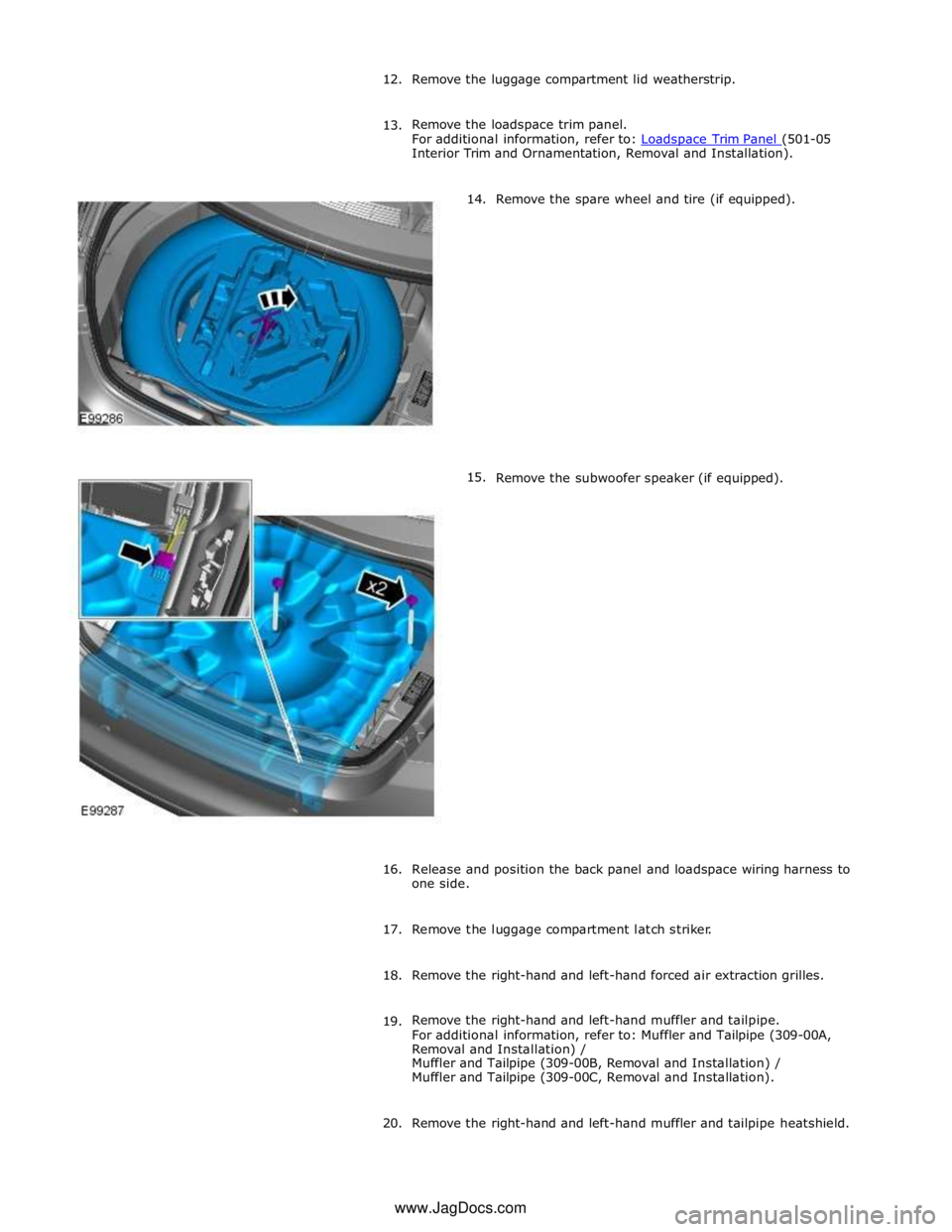
Interior Trim and Ornamentation, Removal and Installation).
14.
15. Remove the spare wheel and tire (if equipped).
Remove the subwoofer speaker (if equipped).
16.
Release and position the back panel and loadspace wiring harness to
one side.
17. Remove the luggage compartment latch striker.
18. Remove the right-hand and left-hand forced air extraction grilles.
19. Remove the right-hand and left-hand muffler and tailpipe.
For additional information, refer to: Muffler and Tailpipe (309-00A,
Removal and Installation) /
Muffler and Tailpipe (309-00B, Removal and Installation) /
Muffler and Tailpipe (309-00C, Removal and Installation).
20. Remove the right-hand and left-hand muffler and tailpipe heatshield. www.JagDocs.com