2010 JAGUAR XFR open hood
[x] Cancel search: open hoodPage 1125 of 3039

- Megafuse fixing nuts
Engine junction box
- Megafuse
- Megafuse fixing nuts
- Fuses
- Engine control module relay Were any circuits or wiring short circuit to ground, short circuit to power, open circuit, high resistance or any
connectors damaged from water ingress, pin damage and/or corrosion?
Yes
Rectify as required
No
Proceed to the next step. A9 'Cooling fan validation procedure' A9: COOLING FAN VALIDATION PROCEDURE 1 Ensure the hood is closed 2 Allow vehicle to idle 3 Switch ON air conditioning and set to lowest temperature and highest fan speed 4 Allow vehicle to reach operating temperature (approximately 90 degrees C). Using the manufacturer approved diagnostic system monitor datalogger signals – Engine Coolant Temperature (0XF405) -and -
Electric Fan PWM Control - Commanded (0X03F9) - as the engine coolant temperature reaches
operating temperature the fan speed should also increase between the values of 9 and 90% Did the cooling fan rotate at increasing speed as engine coolant temperature increased?
Yes
Return vehicle to customer
No
Contact dealer technical support DTC Index
For a list of diagnostic trouble codes (DTCs) that could be logged on this vehicle, please refer to Section 100-00.
REFER to: Electronic Engine Controls (303-14D Electronic Engine Controls - V8 S/C 5.0L Petrol, Diagnosis and Testing). www.JagDocs.com
Page 1871 of 3039

Published: 21-Dec-2012
Battery and Charging System - General Information - Quiescent Drain
Description and Operation
VEHICLE QUIESCENT CURRENT TESTING
On vehicles fitted with a Battery Monitoring System (BMS), the diagnostic routine for quiescent drain testing in the approved
Jaguar or Land Rover diagnostic system should be utilized.
If a customer complains of a vehicle battery that discharges continuously or when left for a prolonged period of time, it is
recommended that a quiescent drain test is performed as described below.
The battery drain should be measured using the approved Jaguar or Land Rover diagnostic system or a Digital Multi-Meter
(DVOM). A procedure for quiescent drain measurement using the diagnostic system is available in the Diagnosis and Testing
section of the Workshop Manual. The vehicle should be in the locked/armed state (for example vehicle alarm fully armed), all
doors, engine and luggage compartment lids are open and latched (so as to appear closed from an electrical point of view).
The test should take place after the vehicle has entered shutdown mode. The time taken for this to occur after the ignition is
switched off varies according to model (Refer to the Topix On line resource for details).
When the vehicle is armed, the effect of the security system Light Emitting Diode (LED) flashing is to cause a pulsation in the
measured current drain. In this case, either the average current should be taken (using a Digital Multi- Meter (DVOM) with an
averaging system) or the current reading taken, ignoring the brief high current peaks.
EQUIPMENT
Approved Jaguar or Land Rover diagnostic system with current probeOR Digital Multi-Meter (DVOM) with current probe.
METHOD OF MEASUREMENT
Using an Approved Jaguar or Land Rover Diagnostic System.
1. Switch off all electrical loads and ensure that the ignition is off
2. Connect the current probe to the approved Jaguar or Land Rover diagnostic system
3. Calibrate the probe
4. Install a clamp around the battery lead/junction box lead
5. Go to the Quiescent Current Testing section in this procedure
Using a digital multimeter
Do not use an in-line DVOM to measure the quiescent drain on vehicles fitted with an electronic throttle (for example XK 2006
onwards). The current exceeds the maximum amount the fuse in the DVOM is capable of handling.
1. Switch off all electrical loads and ensure that the ignition is off
2. Connect the current probe to the digital multmeter
3. Calibrate the probe
4. Install a clamp around the battery lead/junction box lead
5. Go to the Quiescent Current Testing section in this procedure
QUIESCENT CURRENT TESTING
1. Switch ignition to ‘on’ or select ignition mode in keyless vehicles and switch to ‘off’ (do not crank)
2. Remove key from ignition switch (if equipped)
3. Open and latch all doors, hood and luggage compartment lid
4. Lock the vehicle using the remote function on the remote handset. (Single lock only to avoid volumetric alarm arming)
5. Remove any other potential electrical drains such as accessories plugged into accessory sockets
6. Record the amperage readings after the shutdown period referenced in the Topix on line resource for details. Note all
cars from 10MY onwards and XK from 07MY and XF from 08MY should be less than 30mA after 30 minutes
7. Record the final reading on the battery report form
The preferred method of testing following an excessive current consumption figure is to use a current probe around individual
junction box leads to the various suspected circuits to identify a potential cause. This is in preference to the old method of
removing fuses for the following reasons:
The drain may be caused by a module remaining active and preventing the quiescent drain from reducing to normal
levels
The drain may be caused by a relay winding that is activated. Pulling the fuse can allow this to ‘reset’ and the drain will
be lost and go un-diagnosed
QUIESCENT DRAIN - TYPICAL VALUES
NOTE: The quiescent drain after the initial shutdown period should not exceed the value shown in the table.
Jaguar Quiescent Drain Values
MODEL SHUT DOWN PERIOD (minutes) TYPICAL VALUES BATTERY DRAIN (mA) XJS 3.2 60 <30 Sovereign 3.2 60 <37.3
Page 2039 of 3039
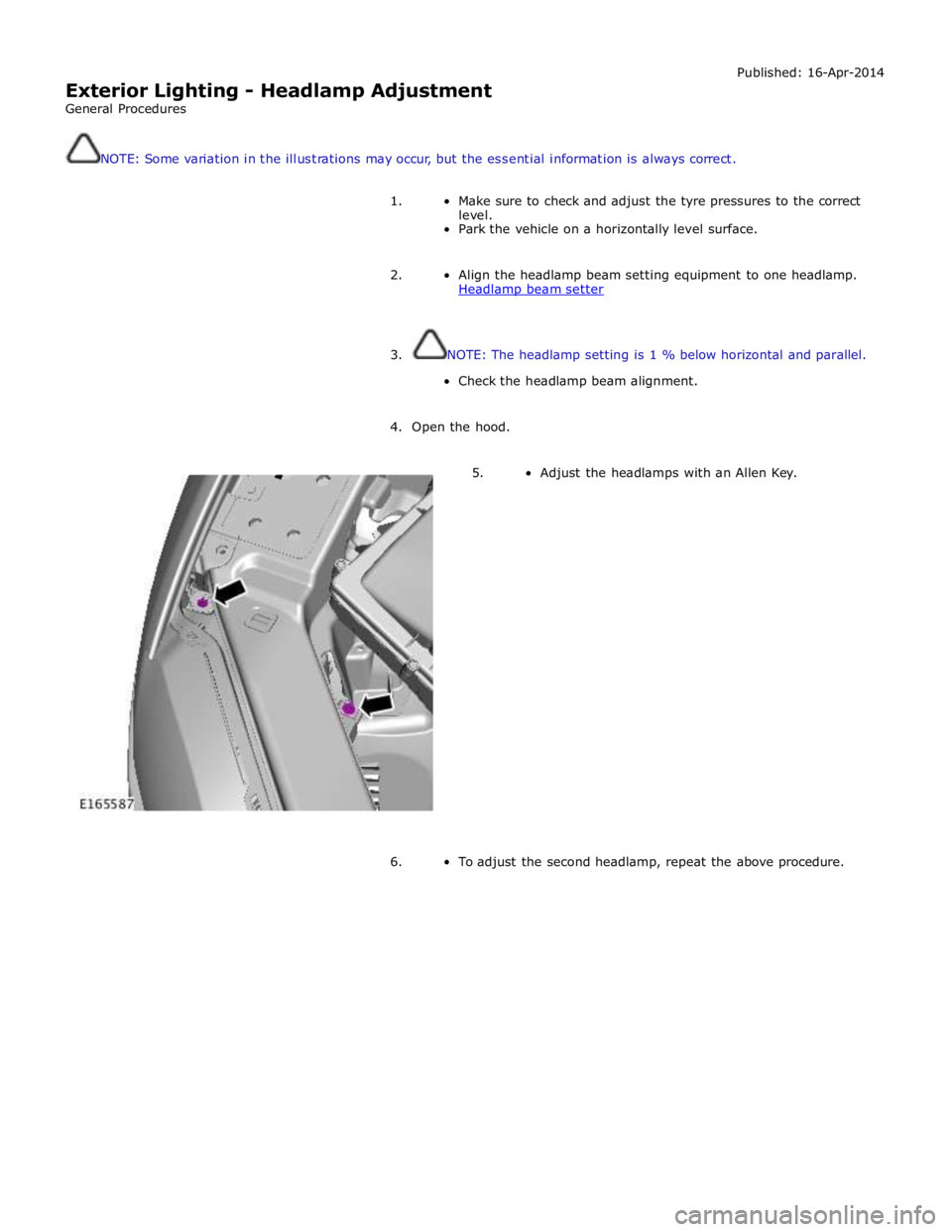
Exterior Lighting - Headlamp Adjustment
General Procedures Published: 16-Apr-2014
NOTE: Some variation in the illustrations may occur, but the essential information is always correct.
1. Make sure to check and adjust the tyre pressures to the correct
level.
Park the vehicle on a horizontally level surface.
2. Align the headlamp beam setting equipment to one headlamp.
Headlamp beam setter
3. NOTE: The headlamp setting is 1 % below horizontal and parallel.
Check the headlamp beam alignment.
4. Open the hood.
5. Adjust the headlamps with an Allen Key.
6. To adjust the second headlamp, repeat the above procedure.
Page 2091 of 3039

DTC Description Possible Cause Action B1D2711
Heater Coolant
Pump
Heater coolant pump control
circuit - short to ground Carry out any pinpoint tests associated with this DTC
using the manufacturer approved diagnostic system.
Refer to the electrical circuit diagrams and check heater
coolant pump control circuit for short to ground B1D2713
Heater Coolant
Pump
Heater coolant pump control
circuit - open circuit Carry out any pinpoint tests associated with this DTC
using the manufacturer approved diagnostic system.
Refer to the electrical circuit diagrams and check heater
coolant pump control circuit for open circuit B1D9796 Tilt Sensor
Component internal failure Suspect the battery backed sounder, check and install a
new battery backed sounder as required P057112
Brake Switch A
Circuit
Footbrake switch circuit - short
to power Refer to the electrical circuit diagrams and check
footbrake switch circuit for short to power P080111
Reverse Inhibit
Control Circuit
Electrochromic rear view mirror,
reverse inhibit circuit - short to
ground Carry out any pinpoint tests associated with this DTC
using the manufacturer approved diagnostic system.
Refer to the electrical circuit diagrams and check
electrochromic rear view mirror, reverse inhibit circuit for
short to ground P080112
Reverse Inhibit
Control Circuit
Electrochromic rear view mirror,
reverse inhibit circuit - short to
power Refer to the electrical circuit diagrams and check
electrochromic rear view mirror, reverse inhibit circuit for
short to power P080113
Reverse Inhibit
Control Circuit
Electrochromic rear view mirror,
reverse inhibit circuit - open
circuit Refer to the electrical circuit diagrams and check
electrochromic rear view mirror, reverse inhibit circuit for
open circuit P085013
Park/Neutral Switch
Input Circuit
Park/Neutral signal circuit -
open circuit Refer to the electrical circuit diagrams and check
Park/Neutral signal circuit for open circuit P162413 Anti-theft System
RJB anti-theft signal circuit -
open circuit Refer to the electrical circuit diagrams and check RJB
anti-theft signal circuit for open circuit P254F13
Engine Hood Switch
Circuit/Open
Hood ajar switch signal circuit -
open circuit Refer to the electrical circuit diagrams and check hood
ajar switch signal circuit for open circuit U001988
Low Speed CAN
Communication Bus
Bus OFF Carry out any pinpoint tests associated with this DTC
using the manufacturer approved diagnostic system. U014200
Lost
Communication
With Body Control
Module "B"
No sub type information Carry out any pinpoint tests associated with this DTC
using the manufacturer approved diagnostic system. U015500
Lost
Communication
With Instrument
Panel Cluster (IPC)
Control Module
No sub type information Carry out any pinpoint tests associated with this DTC
using the manufacturer approved diagnostic system. U015600
Lost
Communication
With Information
Center "A"
No sub type information Carry out any pinpoint tests associated with this DTC
using the manufacturer approved diagnostic system. U016400
Lost
Communication
With HVAC Control
Module
No sub type information Carry out any pinpoint tests associated with this DTC
using the manufacturer approved diagnostic system. U016800
Lost
Communication
With Vehicle
Security Control
Module
No sub type information Check power and ground supplies to vehicle security
module U019900
Lost
Communication
With "Door Control
Module A"
No sub type information Carry out any pinpoint tests associated with this DTC
using the manufacturer approved diagnostic system. U020000
Lost
Communication
With "Door Control
Module B"
No sub type information Carry out any pinpoint tests associated with this DTC
using the manufacturer approved diagnostic system.
Page 2134 of 3039
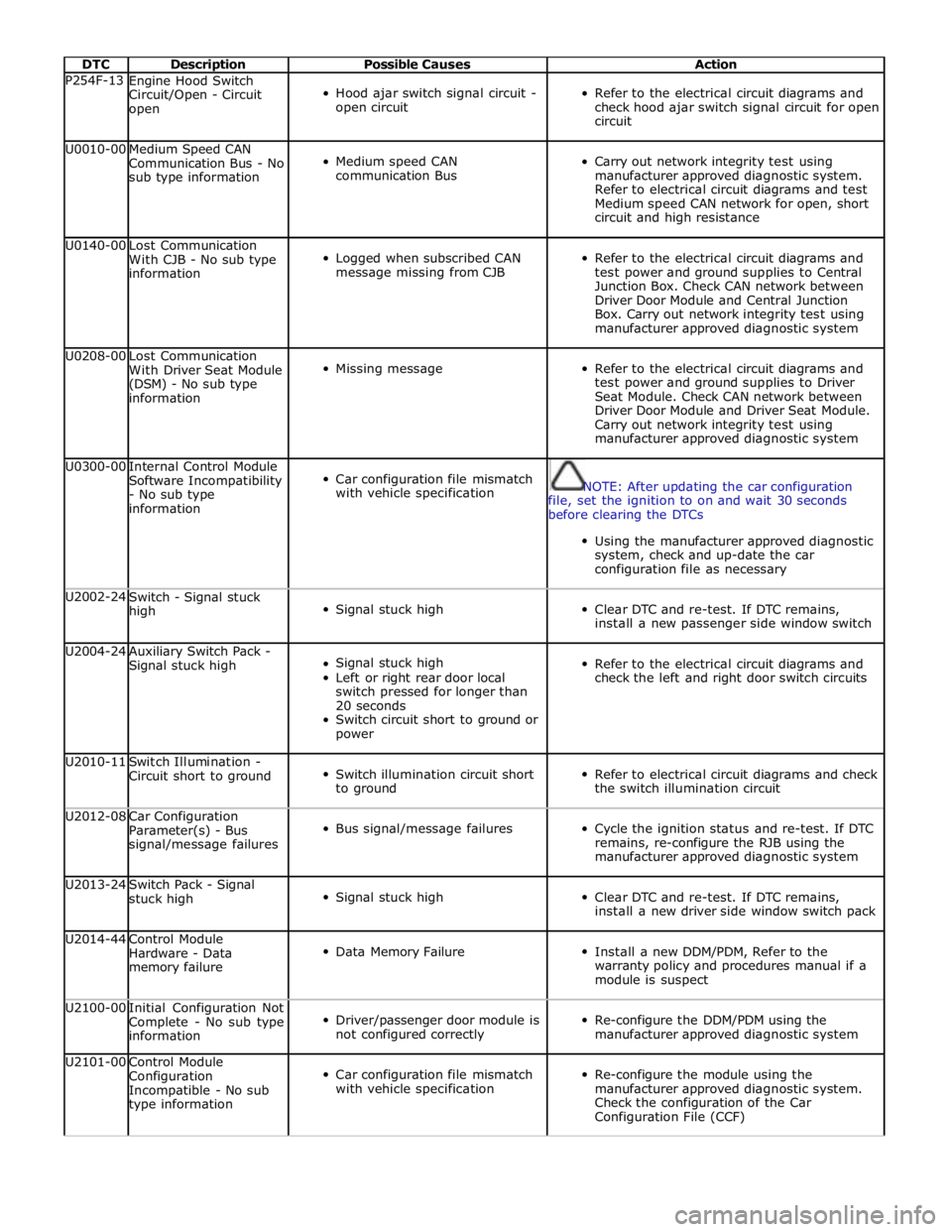
DTC Description Possible Causes Action P254F-13
Engine Hood Switch
Circuit/Open - Circuit
open
Hood ajar switch signal circuit -
open circuit
Refer to the electrical circuit diagrams and
check hood ajar switch signal circuit for open
circuit U0010-00
Medium Speed CAN
Communication Bus - No
sub type information
Medium speed CAN
communication Bus
Carry out network integrity test using
manufacturer approved diagnostic system.
Refer to electrical circuit diagrams and test
Medium speed CAN network for open, short
circuit and high resistance U0140-00
Lost Communication
With CJB - No sub type
information
Logged when subscribed CAN
message missing from CJB
Refer to the electrical circuit diagrams and
test power and ground supplies to Central
Junction Box. Check CAN network between
Driver Door Module and Central Junction
Box. Carry out network integrity test using
manufacturer approved diagnostic system U0208-00
Lost Communication
With Driver Seat Module
(DSM) - No sub type
information
Missing message
Refer to the electrical circuit diagrams and
test power and ground supplies to Driver
Seat Module. Check CAN network between
Driver Door Module and Driver Seat Module.
Carry out network integrity test using
manufacturer approved diagnostic system U0300-00
Internal Control Module
Software Incompatibility
- No sub type
information
Car configuration file mismatch
with vehicle specification
NOTE: After updating the car configuration
file, set the ignition to on and wait 30 seconds
before clearing the DTCs
Using the manufacturer approved diagnostic
system, check and up-date the car
configuration file as necessary U2002-24
Switch - Signal stuck
high
Signal stuck high
Clear DTC and re-test. If DTC remains,
install a new passenger side window switch U2004-24
Auxiliary Switch Pack -
Signal stuck high
Signal stuck high
Left or right rear door local
switch pressed for longer than
20 seconds
Switch circuit short to ground or
power
Refer to the electrical circuit diagrams and
check the left and right door switch circuits U2010-11
Switch Illumination -
Circuit short to ground
Switch illumination circuit short
to ground
Refer to electrical circuit diagrams and check
the switch illumination circuit U2012-08
Car Configuration
Parameter(s) - Bus
signal/message failures
Bus signal/message failures
Cycle the ignition status and re-test. If DTC
remains, re-configure the RJB using the
manufacturer approved diagnostic system U2013-24
Switch Pack - Signal
stuck high
Signal stuck high
Clear DTC and re-test. If DTC remains,
install a new driver side window switch pack U2014-44
Control Module
Hardware - Data
memory failure
Data Memory Failure
Install a new DDM/PDM, Refer to the
warranty policy and procedures manual if a
module is suspect U2100-00
Initial Configuration Not
Complete - No sub type
information
Driver/passenger door module is
not configured correctly
Re-configure the DDM/PDM using the
manufacturer approved diagnostic system U2101-00
Control Module
Configuration
Incompatible - No sub
type information
Car configuration file mismatch
with vehicle specification
Re-configure the module using the
manufacturer approved diagnostic system.
Check the configuration of the Car
Configuration File (CCF)
Page 2495 of 3039
Published: 18-Mar-2014
Handles, Locks, Latches and Entry Systems - Locks, Latches and Entry Systems
Diagnosis and Testing
Principle of Operation
For a detailed description of the locks, latches and entry systems and operation, refer to the relevant Description and
Operation section of the workshop manual. REFER to: Handles, Locks, Latches and Entry Systems (501-14, Description and
Operation).
Inspection and Verification
CAUTION: Diagnosis by substitution from a donor vehicle is NOT acceptable. Substitution of control modules does not
guarantee confirmation of a fault and may also cause additional faults in the vehicle being checked and/or the donor vehicle
NOTE: Check and rectify basic faults before beginning diagnostic routines involving pinpoint tests
1. Verify the customer concern, to be sure the correct issue is investigated
2. Visually inspect for obvious signs of damage and system integrity
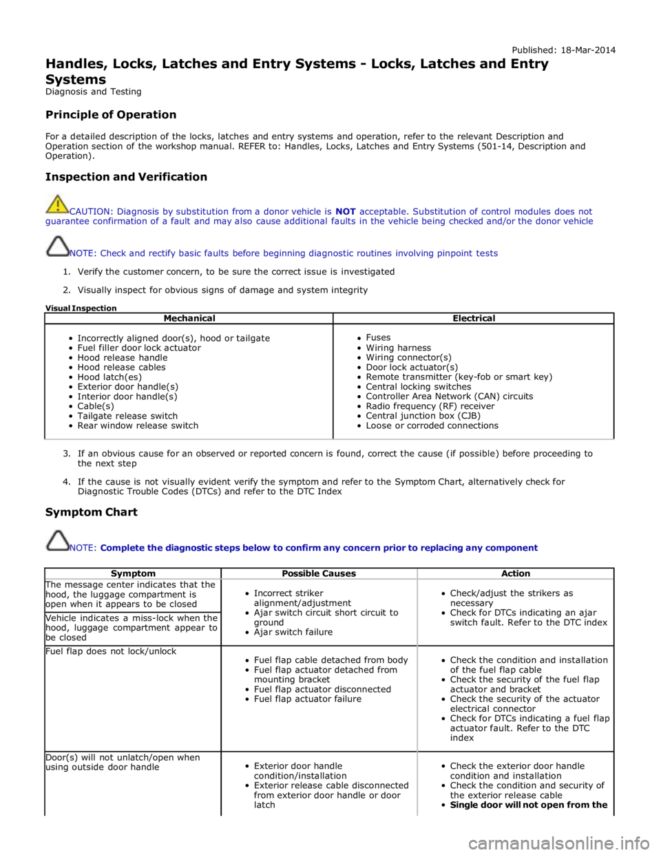
Visual Inspection
Mechanical Electrical
Incorrectly aligned door(s), hood or tailgate
Fuel filler door lock actuator
Hood release handle
Hood release cables
Hood latch(es)
Exterior door handle(s)
Interior door handle(s)
Cable(s)
Tailgate release switch
Rear window release switch
Fuses
Wiring harness
Wiring connector(s)
Door lock actuator(s)
Remote transmitter (key-fob or smart key)
Central locking switches
Controller Area Network (CAN) circuits
Radio frequency (RF) receiver
Central junction box (CJB)
Loose or corroded connections
3. If an obvious cause for an observed or reported concern is found, correct the cause (if possible) before proceeding to
the next step
4. If the cause is not visually evident verify the symptom and refer to the Symptom Chart, alternatively check for
Diagnostic Trouble Codes (DTCs) and refer to the DTC Index
Symptom Chart
NOTE: Complete the diagnostic steps below to confirm any concern prior to replacing any component
Symptom Possible Causes Action The message center indicates that the
hood, the luggage compartment is
open when it appears to be closed
Incorrect striker
alignment/adjustment
Ajar switch circuit short circuit to
ground
Ajar switch failure
Check/adjust the strikers as
necessary
Check for DTCs indicating an ajar
switch fault. Refer to the DTC index Vehicle indicates a miss-lock when the
hood, luggage compartment appear to
be closed Fuel flap does not lock/unlock
Fuel flap cable detached from body
Fuel flap actuator detached from
mounting bracket
Fuel flap actuator disconnected
Fuel flap actuator failure
Check the condition and installation
of the fuel flap cable
Check the security of the fuel flap
actuator and bracket
Check the security of the actuator
electrical connector
Check for DTCs indicating a fuel flap
actuator fault. Refer to the DTC
index Door(s) will not unlatch/open when
using outside door handle
Exterior door handle
condition/installation
Exterior release cable disconnected
from exterior door handle or door
latch
Check the exterior door handle
condition and installation
Check the condition and security of
the exterior release cable
Single door will not open from the
Page 2686 of 3039
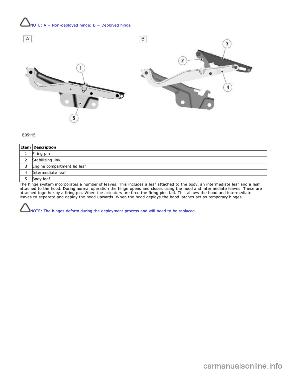
NOTE: A = Non-deployed hinge; B = Deployed hinge
Item Description 1 Firing pin 2 Stabilizing link 3 Engine compartment lid leaf 4 Intermediate leaf 5 Body leaf The hinge system incorporates a number of leaves. This includes a leaf attached to the body, an intermediate leaf and a leaf
attached to the hood. During normal operation the hinge opens and closes using the hood and intermediate leaves. These are
attached together by a firing pin. When the actuators are fired the firing pins fail. This allows the hood and intermediate
leaves to separate and deploy the hood upwards. When the hood deploys the hood latches act as temporary hinges.
NOTE: The hinges deform during the deployment process and will need to be replaced.
Page 2688 of 3039
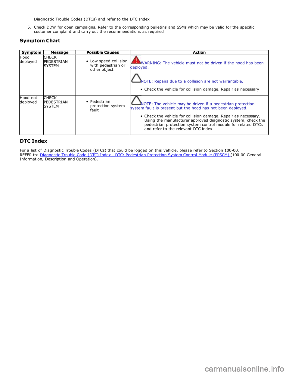
Diagnostic Trouble Codes (DTCs) and refer to the DTC Index
5. Check DDW for open campaigns. Refer to the corresponding bulletins and SSMs which may be valid for the specific
customer complaint and carry out the recommendations as required
Symptom Chart
Symptom Message Possible Causes Action Hood
deployed CHECK
PEDESTRIAN
SYSTEM
Low speed collision
with pedestrian or
other object
WARNING: The vehicle must not be driven if the hood has been
deployed.
NOTE: Repairs due to a collision are not warrantable.
Check the vehicle for collision damage. Repair as necessary Hood not
deployed CHECK
PEDESTRIAN
SYSTEM
Pedestrian
protection system
fault
NOTE: The vehicle may be driven if a pedestrian protection
system fault is present but the hood has not been deployed.
Check the vehicle for collision damage. Repair as necessary.
Using the manufacturer approved diagnostic system, check the
pedestrian protection system control module for related DTCs
and refer to the relevant DTC index
DTC Index
For a list of Diagnostic Trouble Codes (DTCs) that could be logged on this vehicle, please refer to Section 100-00.
REFER to: Diagnostic Trouble Code (DTC) Index - DTC: Pedestrian Protection System Control Module (PPSCM) (100-00 General Information, Description and Operation).