2010 JAGUAR XFR open hood
[x] Cancel search: open hoodPage 31 of 3039

Removal and InstallationFender Apron Closing Panel Front Section
Fender Apron Panel
Fender Apron Panel Closing Panel
Fender Apron Panel Front Extension
Fender Apron Panel Front Section
Front Bumper Mounting
Front Fender
Front Fender Support Bracket
Front Side Member
Front Side Member and Suspension Top Mount Assembly
Front Side Member Closing Panel
Front Side Member Closing Panel Section
Front Side Member Section
Front Wheelhouse Section
Hood Latch Panel
Hood Latch Panel Mounting Bracket501-28: Roof Sheet Metal Repairs
Description and OperationRoofRemoval and InstallationRoof Panel - Vehicles With: Sliding Roof Opening Panel
Roof Panel - Vehicles Without: Sliding Roof Opening Panel501-29: Side Panel Sheet Metal Repairs
Description and OperationSide Panel Sheet MetalRemoval and InstallationA-Pillar Outer Panel
A-Pillar Reinforcement
B-Pillar Inner Panel
B-Pillar Reinforcement
Front Door Skin Panel
Rear Door Skin Panel
Rocker Panel
Rocker Panel and B-Pillar Outer Panel
Rocker Panel Front Section
Rocker Panel Inner Reinforcement
Rocker Panel Rear Section501-30: Rear End Sheet Metal Repairs
Description and OperationRear End Sheet Metal
Page 215 of 3039

Published: 18-Apr-2014
General Information - Diagnostic Trouble Code (DTC) Index DTC: Pedestrian
Protection System Control Module (PPSCM)
Description and Operation
Pedestrian Protection System Control Module (PPSCM)
WARNING: TO AVOID ACCIDENTAL DEPLOYMENT AND POSSIBLE PERSONAL INJURY, THE BACKUP POWER SUPPLY MUST
BE DEPLETED BEFORE REPAIRING OR REPLACING ANY PEDESTRIAN PROTECTION SYSTEM COMPONENTS. TO DEPLETE THE
BACKUP POWER SUPPLY ENERGY, DISCONNECT THE BATTERY GROUND CABLE AND WAIT TWO MINUTES. FAILURE TO FOLLOW
THIS INSTRUCTION MAY RESULT IN PERSONAL INJURY.
CAUTION: Diagnosis by substitution from a donor vehicle is NOT acceptable. Substitution of control modules does not
guarantee confirmation of a fault, and may also cause additional faults in the vehicle being tested and/or the donor vehicle.
NOTES:
If the control module or a component is suspect and the vehicle remains under manufacturer warranty, refer to the
Warranty Policy and Procedures manual, or determine if any prior approval programme is in operation, prior to the installation
of a new module/component.
Generic scan tools may not read the codes listed, or may read only 5-digit codes. Match the 5 digits from the scan tool to
the first 5 digits of the 7-digit code listed to identify the fault (the last 2 digits give extra information read by the
manufacturer-approved diagnostic system).
When performing voltage or resistance tests, always use a digital multimeter accurate to three decimal places, and with
an up-to-date calibration certificate. When testing resistance always take the resistance of the digital multimeter leads into
account.
Check and rectify basic faults before beginning diagnostic routines involving pinpoint tests.
Inspect connectors for signs of water ingress, and pins for damage and/or corrosion.
If DTCs are recorded and, after performing the pinpoint tests, a fault is not present, an intermittent concern may be the
cause. Always check for loose connections and corroded terminals.
Check DDW for open campaigns. Refer to the corresponding bulletins and SSMs which may be valid for the specific
customer complaint and carry out the recommendations as required.
The table below lists all Diagnostic Trouble Codes (DTCs) that could be logged in the Pedestrian Protection System Control
Module (PPSCM). For additional diagnosis and testing information, refer to the relevant Diagnosis and Testing section in the
workshop manual.
For additional information, refer to: Pedestrian Protection System (501-20C Pedestrian Protection System, Diagnosis and Testing).
DTC Description Possible Causes Action B1001-11
Right Hood Deployment
Control - Circuit short to
ground
Right hood deployment
control circuit short circuit
to ground
Refer to the electrical circuit diagrams and
check the right hood deployment control circuit
for short circuit to ground. Install a new wiring
harness as necessary. If no wiring harness
fault exists, using the manufacturer approved
diagnostic system, clear the DTCs and retest.
If the fault persists, install a new right hood
deployment control B1001-12
Right Hood Deployment
Control - Circuit short to
battery
Right hood deployment
control circuit short circuit
to power
Refer to the electrical circuit diagrams and
check the right hood deployment control circuit
for short circuit to power. Install a new wiring
harness as necessary. If no wiring harness
fault exists, using the manufacturer approved
diagnostic system, clear the DTCs and retest.
If the fault persists, install a new right hood
deployment control
Page 874 of 3039

Refer to: Specifications (303-01D Engine - V8 S/C 5.0L Petrol, Specifications).
Clean any residual engine oil from the oil filler cap area.
6.
7. CAUTION: Make sure that the vehicle has been left for 5 minutes
from filling with oil.
Follow the Steps 9-13 before starting the engine.
8.
Start the engine and allow to run for 10 minutes, stop the
engine.
Check for leaks.
9. CAUTIONS:
Make sure that the selector lever and the gearshift mechanism are
in the park (P) position.
Make sure that the hood is open.
Turn the ignition on.
Page 881 of 3039

Specifications).
Clean any residual engine oil from the oil filler cap area.
4.
5. CAUTION: Make sure that the vehicle has been left for 5 minutes
from filling with oil.
Follow the Steps 7-11 before starting the engine.
6.
Start the engine and allow to run for 10 minutes, stop the
engine.
Check for leaks.
7. CAUTIONS:
Make sure that the selector lever and the gearshift mechanism are
in the park (P) position.
Make sure that the hood is open.
Turn the ignition on. www.JagDocs.com
Page 889 of 3039

17.
18. Torque: 10 Nm
NOTE: Install a new sealing washer.
Torque: 24 Nm
19.
20. Refer to: Battery Disconnect and Connect (414-01 Battery, Mounting and Cables, General Procedures).
CAUTION: Make sure that the vehicle is left for 5 minutes from filling with oil and
that the engine oil level is reading at least minimum (by following Steps 23-27), before
starting the engine.
Fill the engine with oil - for filling values on vehicles without supercharger:
Refer to: Specifications (303-01C Engine - V8 5.0L Petrol, Specifications). Fill the engine with oil - for filling values on vehicles with supercharger:
Refer to: Specifications (303-01D Engine - V8 S/C 5.0L Petrol, Specifications). Clean any residual engine oil from the oil filler cap area.
21.
oil. CAUTION: Make sure that the vehicle has been left for 5 minutes from filling with
Follow the Steps 23-27 before starting the engine.
22.
Start the engine and allow to run for 10 minutes, stop the engine.
Check for leaks.
23. CAUTIONS:
Make sure that the selector lever and the gearshift mechanism are in the park (P)
position.
Make sure that the hood is open.
Turn the ignition on.
Page 896 of 3039

Refer to: Specifications (303-01D Engine - V8 S/C 5.0L Petrol, Specifications).
Clean any residual engine oil from the oil filler cap area.
13. CAUTION: Make sure that the vehicle has been left for 5 minutes
from filling with oil.
Follow the Steps 15-19 before starting the engine.
14.
Start the engine and allow to run for 10 minutes, stop the
engine.
Check for leaks.
15. CAUTIONS:
Make sure that the selector lever and the gearshift mechanism are
in the park (P) position.
Make sure that the hood is open.
Turn the ignition on.
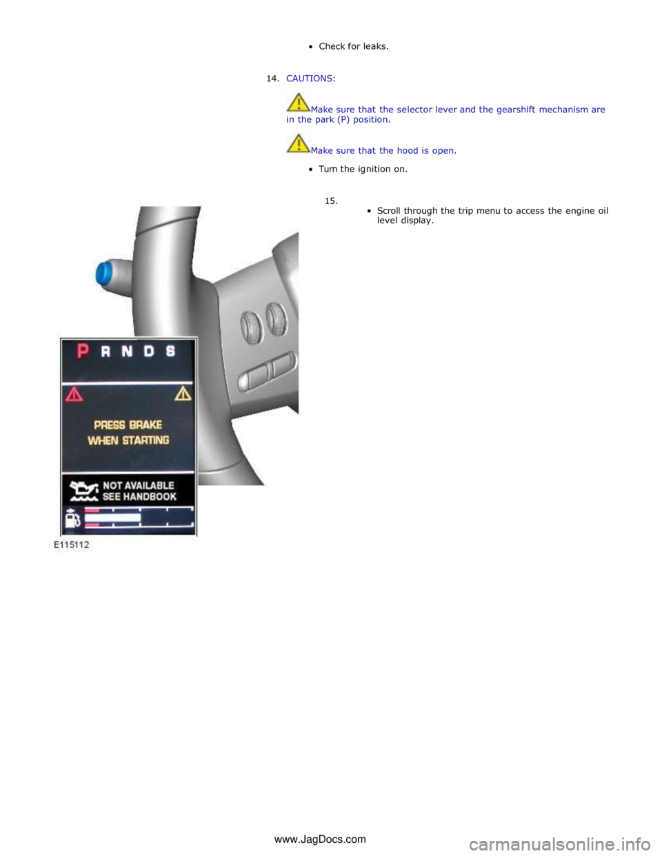
16.
Scroll through the trip menu to access the engine oil
level display. www.JagDocs.com
Page 1081 of 3039

Check for leaks.
14. CAUTIONS:
Make sure that the selector lever and the gearshift mechanism are
in the park (P) position.
Make sure that the hood is open.
Turn the ignition on.
15.
Scroll through the trip menu to access the engine oil
level display. www.JagDocs.com
Page 1124 of 3039

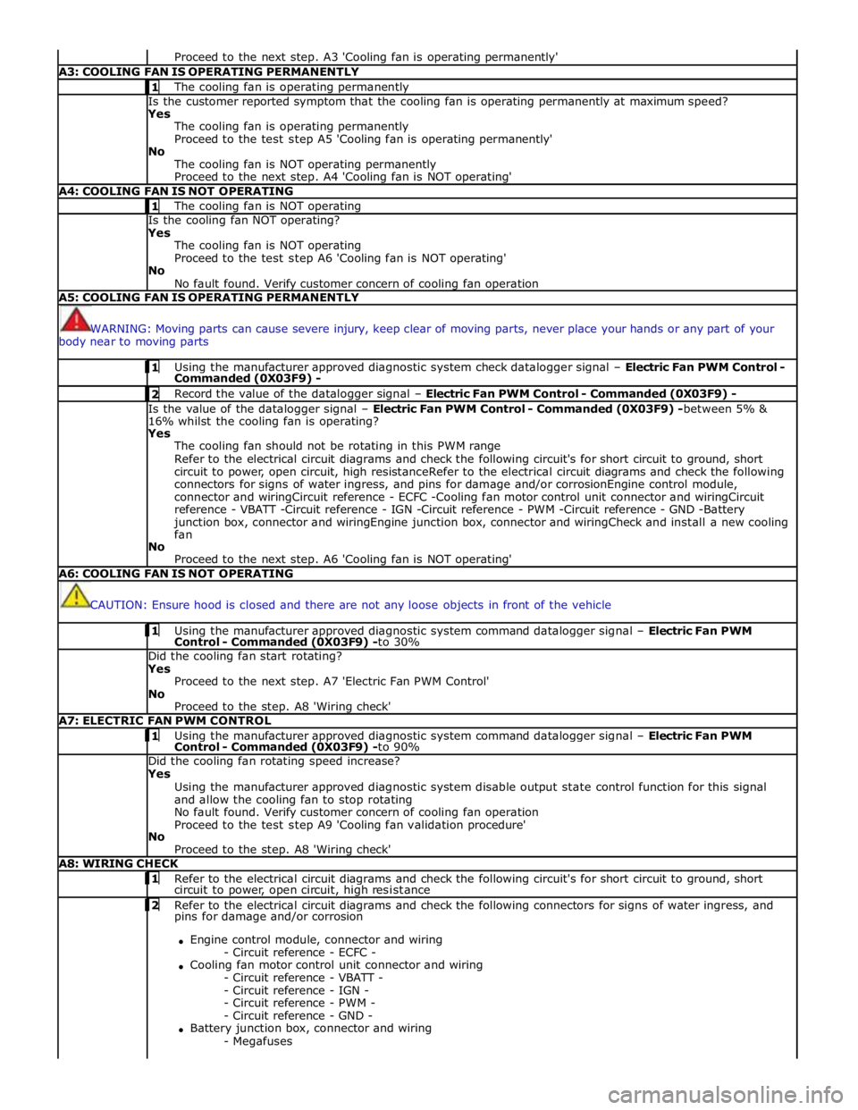
Proceed to the next step. A3 'Cooling fan is operating permanently' A3: COOLING FAN IS OPERATING PERMANENTLY 1 The cooling fan is operating permanently Is the customer reported symptom that the cooling fan is operating permanently at maximum speed?
Yes
The cooling fan is operating permanently
Proceed to the test step A5 'Cooling fan is operating permanently'
No
The cooling fan is NOT operating permanently
Proceed to the next step. A4 'Cooling fan is NOT operating' A4: COOLING FAN IS NOT OPERATING 1 The cooling fan is NOT operating Is the cooling fan NOT operating?
Yes
The cooling fan is NOT operating
Proceed to the test step A6 'Cooling fan is NOT operating'
No
No fault found. Verify customer concern of cooling fan operation A5: COOLING FAN IS OPERATING PERMANENTLY
WARNING: Moving parts can cause severe injury, keep clear of moving parts, never place your hands or any part of your
body near to moving parts 1 Using the manufacturer approved diagnostic system check datalogger signal – Electric Fan PWM Control - Commanded (0X03F9) - 2 Record the value of the datalogger signal – Electric Fan PWM Control - Commanded (0X03F9) - Is the value of the datalogger signal – Electric Fan PWM Control - Commanded (0X03F9) -between 5% &
16% whilst the cooling fan is operating?
Yes
The cooling fan should not be rotating in this PWM range
Refer to the electrical circuit diagrams and check the following circuit's for short circuit to ground, short
circuit to power, open circuit, high resistanceRefer to the electrical circuit diagrams and check the following
connectors for signs of water ingress, and pins for damage and/or corrosionEngine control module,
connector and wiringCircuit reference - ECFC -Cooling fan motor control unit connector and wiringCircuit
reference - VBATT -Circuit reference - IGN -Circuit reference - PWM -Circuit reference - GND -Battery
junction box, connector and wiringEngine junction box, connector and wiringCheck and install a new cooling
fan
No
Proceed to the next step. A6 'Cooling fan is NOT operating' A6: COOLING FAN IS NOT OPERATING
CAUTION: Ensure hood is closed and there are not any loose objects in front of the vehicle 1 Using the manufacturer approved diagnostic system command datalogger signal – Electric Fan PWM Control - Commanded (0X03F9) -to 30% Did the cooling fan start rotating?
Yes
Proceed to the next step. A7 'Electric Fan PWM Control'
No
Proceed to the step. A8 'Wiring check' A7: ELECTRIC FAN PWM CONTROL 1 Using the manufacturer approved diagnostic system command datalogger signal – Electric Fan PWM Control - Commanded (0X03F9) -to 90% Did the cooling fan rotating speed increase?
Yes
Using the manufacturer approved diagnostic system disable output state control function for this signal
and allow the cooling fan to stop rotating
No fault found. Verify customer concern of cooling fan operation
Proceed to the test step A9 'Cooling fan validation procedure'
No
Proceed to the step. A8 'Wiring check' A8: WIRING CHECK 1 Refer to the electrical circuit diagrams and check the following circuit's for short circuit to ground, short circuit to power, open circuit, high resistance 2 Refer to the electrical circuit diagrams and check the following connectors for signs of water ingress, and pins for damage and/or corrosion
Engine control module, connector and wiring
- Circuit reference - ECFC -
Cooling fan motor control unit connector and wiring
- Circuit reference - VBATT -
- Circuit reference - IGN -
- Circuit reference - PWM -
- Circuit reference - GND -
Battery junction box, connector and wiring
- Megafuses