2010 JAGUAR XFR mirror
[x] Cancel search: mirrorPage 1367 of 3039
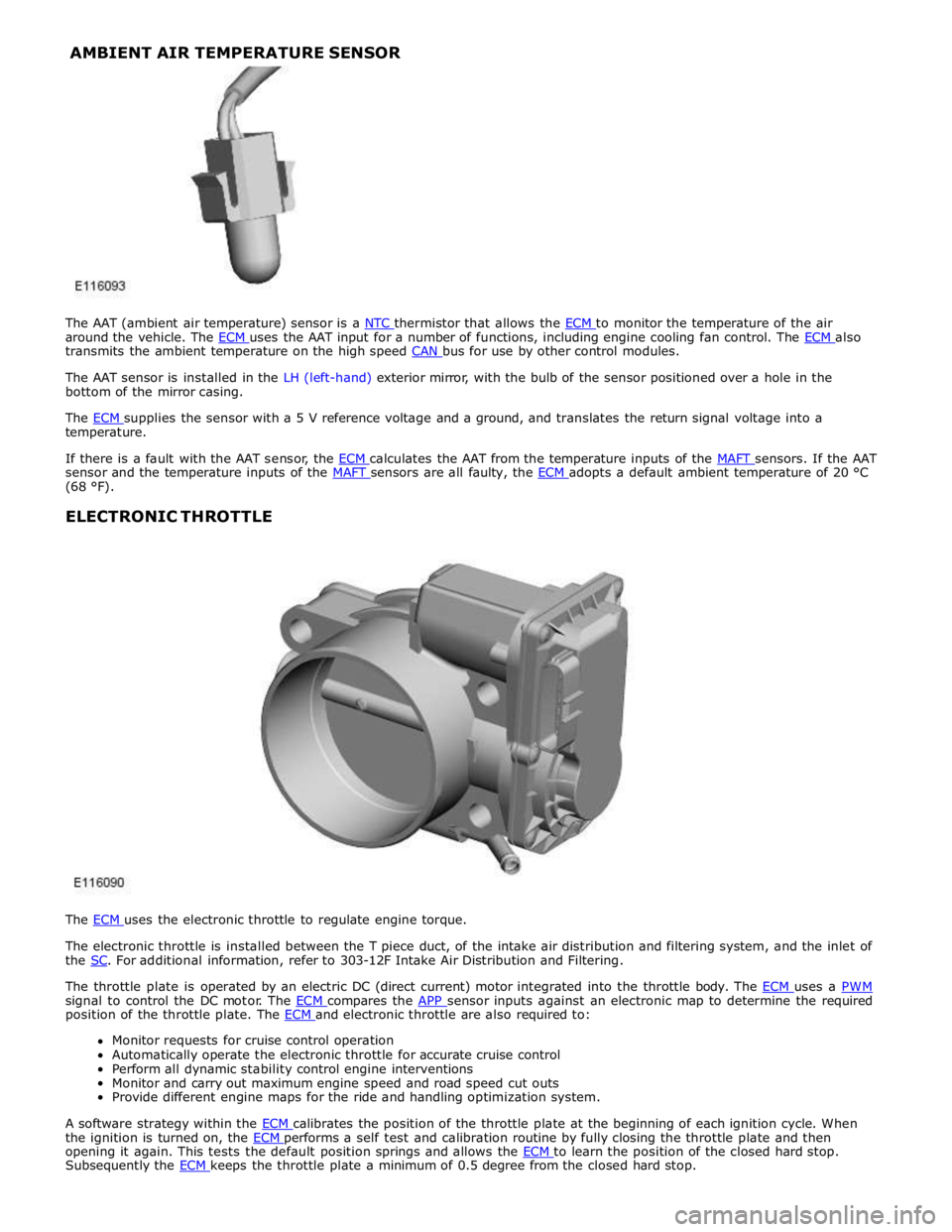
around the vehicle. The ECM uses the AAT input for a number of functions, including engine cooling fan control. The ECM also transmits the ambient temperature on the high speed CAN bus for use by other control modules.
The AAT sensor is installed in the LH (left-hand) exterior mirror, with the bulb of the sensor positioned over a hole in the
bottom of the mirror casing.
The ECM supplies the sensor with a 5 V reference voltage and a ground, and translates the return signal voltage into a temperature.
If there is a fault with the AAT sensor, the ECM calculates the AAT from the temperature inputs of the MAFT sensors. If the AAT sensor and the temperature inputs of the MAFT sensors are all faulty, the ECM adopts a default ambient temperature of 20 °C (68 °F).
ELECTRONIC THROTTLE
The ECM uses the electronic throttle to regulate engine torque.
The electronic throttle is installed between the T piece duct, of the intake air distribution and filtering system, and the inlet of
the SC. For additional information, refer to 303-12F Intake Air Distribution and Filtering.
The throttle plate is operated by an electric DC (direct current) motor integrated into the throttle body. The ECM uses a PWM signal to control the DC motor. The ECM compares the APP sensor inputs against an electronic map to determine the required position of the throttle plate. The ECM and electronic throttle are also required to: Monitor requests for cruise control operation
Automatically operate the electronic throttle for accurate cruise control
Perform all dynamic stability control engine interventions
Monitor and carry out maximum engine speed and road speed cut outs
Provide different engine maps for the ride and handling optimization system.
A software strategy within the ECM calibrates the position of the throttle plate at the beginning of each ignition cycle. When the ignition is turned on, the ECM performs a self test and calibration routine by fully closing the throttle plate and then opening it again. This tests the default position springs and allows the ECM to learn the position of the closed hard stop. Subsequently the ECM keeps the throttle plate a minimum of 0.5 degree from the closed hard stop. AMBIENT AIR TEMPERATURE SENSOR
Page 1706 of 3039
Climate Control - Control Components - Overview
Description and Operation
Overview Published: 11-May-2011
The climate control system is controlled by the ATC (automatic temperature control) module. It controls the heating and
ventilation system and the A/C (air conditioning) system to regulate the temperature, volume and distribution of air into the
passenger compartment. The system is a fully automatic dual zone system capable of maintaining individual temperature
levels selected for the LH (left-hand) and RH (right-hand) sides of the passenger compartment, up to a maximum differential
of approximately 3 ºC (5.4 ºF). Manual overrides for the system include inlet air source, blower speed and air distribution.
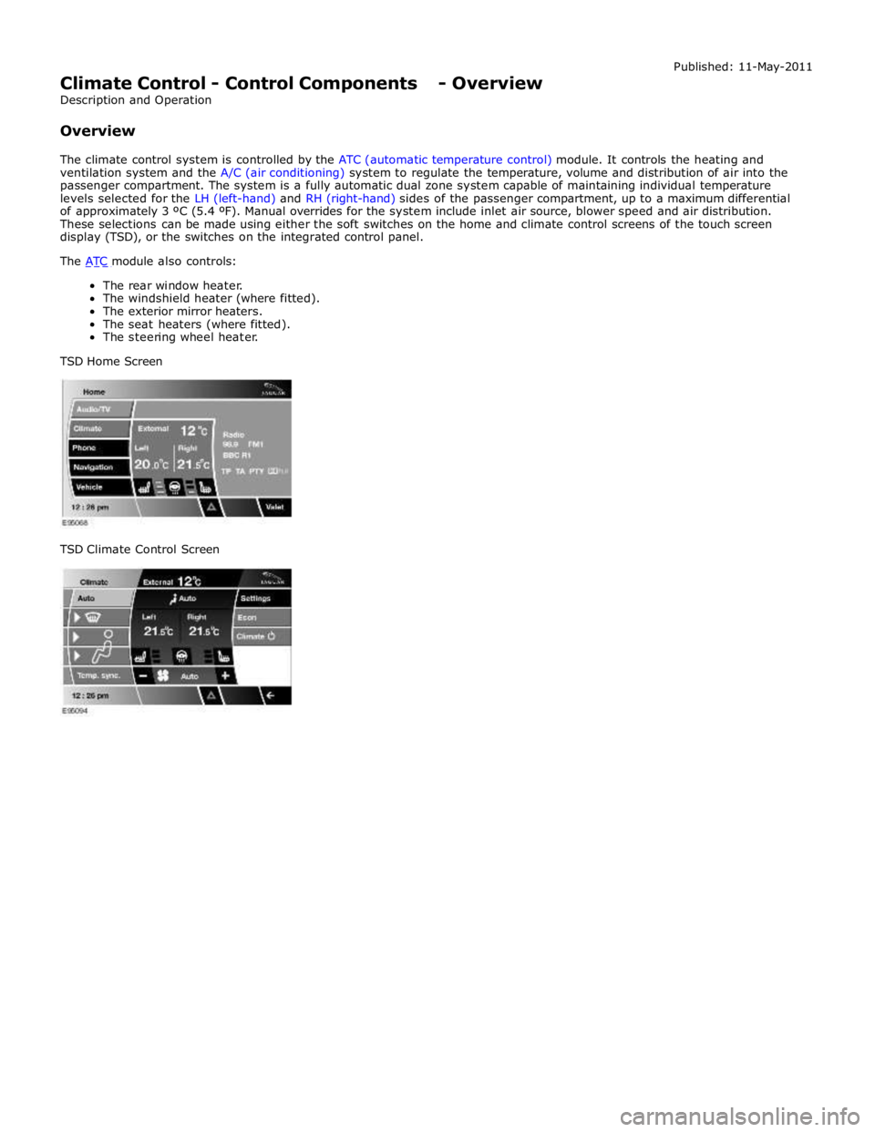
These selections can be made using either the soft switches on the home and climate control screens of the touch screen
display (TSD), or the switches on the integrated control panel.
The ATC module also controls: The rear window heater.
The windshield heater (where fitted).
The exterior mirror heaters.
The seat heaters (where fitted).
The steering wheel heater.
TSD Home Screen
TSD Climate Control Screen
Page 1711 of 3039

rear window heater switch is pressed or the engine stops.
Automatic operation during a journey is initiated when low ambient air temperatures are experienced and the vehicle has been
travelling for a set period of time above a threshold speed. In this instance, no feedback is given to the driver to inform him
the rear window heater is operational (the switch LED is not illuminated). The duration of heater operation is variable depending on the ambient air temperature, vehicle speed and the amount of time the vehicle has been travelling.
Windshield Heater (Where Fitted)
Windshield heater operation is only enabled when the engine is running. The ATC module controls operation of the windshield heater using two relays in the EJB (engine junction box). When windshield heater operation is required, the ATC module broadcasts a message to the CJB on the medium speed CAN bus. On receipt of the message, the CJB energizes the relays by providing a ground path for both relay coils. This allows a battery feed to flow across the relays to power the windshield left
and right heater elements.
There are two modes of windshield heater operation; manual and automatic.
Manual operation is activated by pressing the windshield heater switch on the integrated control panel. When the switch is
pressed, the status LED in the switch illuminates and the windshield heater elements are energized. Manual operation is discontinued when the windshield heater switch is pressed a second time, 5 minutes have elapsed (the heating phase), or the
engine stops. If manual operation is discontinued by the engine stopping, the previous heating phase is resumed if the engine
is re-started within 30 seconds.
There are two variants of automatic operation; automatic operation at the start of a journey and automatic operation during a
journey.
Automatic operation at the start of a journey is initiated if the ambient air temperature is below 5 °C (41 °F). In this instance,
the switch LED is illuminated and the heater elements are energized for 6.5 minutes. Automatic operation is discontinued if the windshield heater switch is pressed or the engine stops.
Automatic operation during a journey is initiated when low ambient air temperatures are experienced and the vehicle has been
travelling for a set period of time above a threshold speed. In this instance, no feedback is given to the driver to inform him
the windshield heater is operational (the switch LED is not illuminated) and the duration of operation is variable depending upon the ambient air temperature, vehicle speed and the amount of time the vehicle has been travelling.
Exterior Mirror Heaters
Operation of the exterior mirror heaters is fully automatic and not controllable by the driver. Exterior mirror heater operation is
determined by ambient air temperature and windshield wiper status. When ambient air temperature reaches a pre-determined
level, the ATC module broadcasts an exterior mirror heating request to the door modules over the medium speed CAN bus. On receipt of this message, the door modules provide feed and ground connections to both exterior mirror heater elements.
The amount of time the exterior mirror heaters are operational increases if the windshield wipers are switched on. This ensures
the mirrors remain mist free in damp and wet conditions, where there is an increased risk of misting.
Seat Heaters (Where Fitted)
There are four seat heater settings available; off, 1, 2 and 3, which can be selected on the home and climate control screens
of the TSD. The heat setting is relayed to the vehicle occupants through a graduated display on the TSD.
Operation of the heated seats is controlled by the ATC module. When the ATC module receives a heating request from the TSD, it broadcasts a message to the CJB over the medium speed CAN bus. The CJB then provides a hardwired 12 V supply to the three heater elements in the related front seat. The heater elements, two in the seat cushion and one in the seat squab,
are wired in series. The ATC module monitors seat temperature using a temperature sensor located in each seat cushion. The CJB provides the temperature sensors with a 5 V supply. The level of the returned voltage back to the CJB is proportional to the seat temperature. The value of the return signal is broadcast to the ATC module, over the medium speed CAN bus, which allows it to control the seat temperature to the required level. The ATC module will suspend or disable operation of the seat heaters if any of the following occur:
Battery voltage exceeds 16.5 ± 0.3 V for more than 5 seconds. Seat heating is re-enabled when battery voltage
decreases to 16.2 ± 0.3 V.
If a short or open circuit is detected.
If the seat heat temperature rises significantly above the target temperature setting.
The graduated display on the TSD remains illuminated until the seat heaters are turned off or the engine stops. If the engine
is restarted within 30 seconds the seat heater resumes the previous heating level.
Page 1715 of 3039
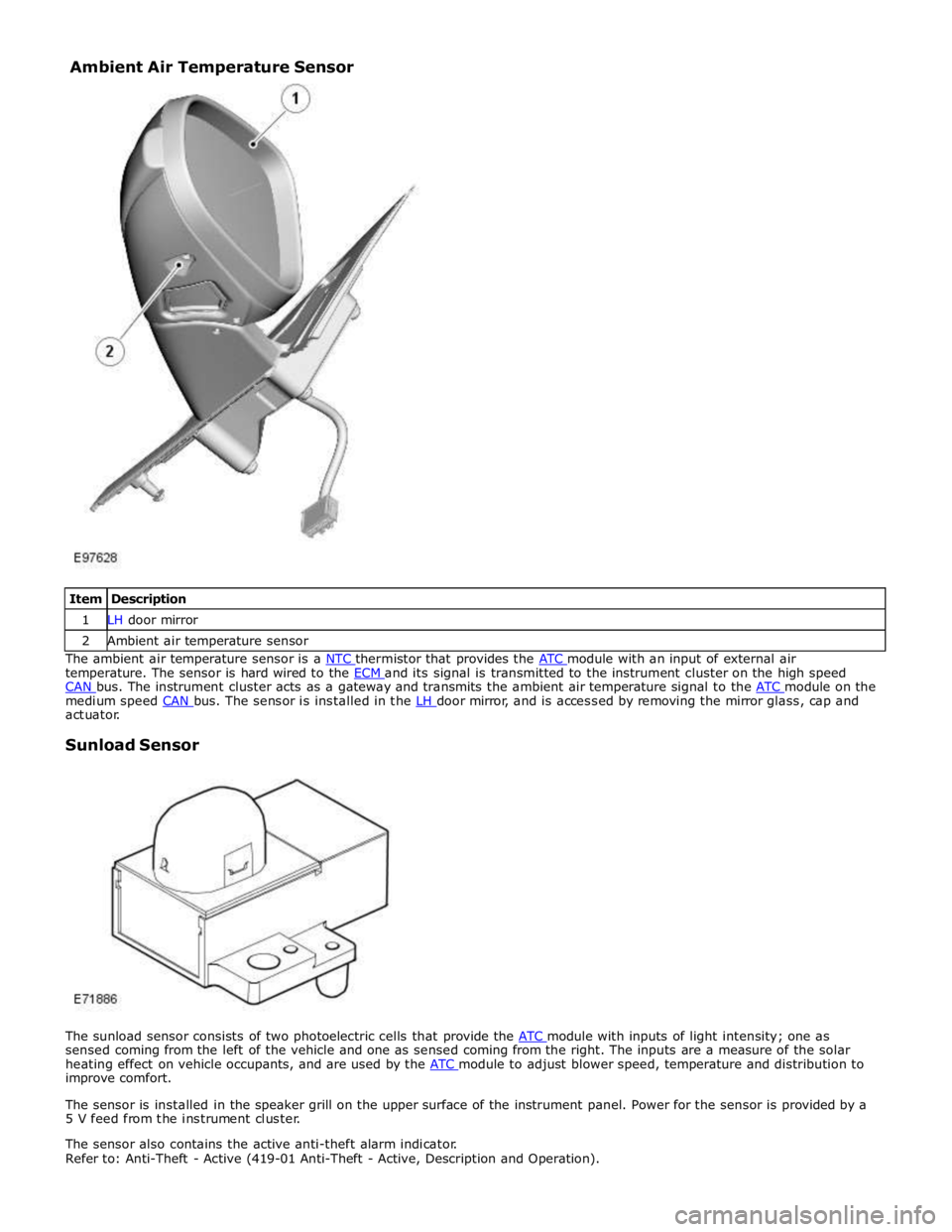
1 LH door mirror 2 Ambient air temperature sensor The ambient air temperature sensor is a NTC thermistor that provides the ATC module with an input of external air temperature. The sensor is hard wired to the ECM and its signal is transmitted to the instrument cluster on the high speed CAN bus. The instrument cluster acts as a gateway and transmits the ambient air temperature signal to the ATC module on the medium speed CAN bus. The sensor is installed in the LH door mirror, and is accessed by removing the mirror glass, cap and actuator.
Sunload Sensor
The sunload sensor consists of two photoelectric cells that provide the ATC module with inputs of light intensity; one as sensed coming from the left of the vehicle and one as sensed coming from the right. The inputs are a measure of the solar
heating effect on vehicle occupants, and are used by the ATC module to adjust blower speed, temperature and distribution to improve comfort.
The sensor is installed in the speaker grill on the upper surface of the instrument panel. Power for the sensor is provided by a
5 V feed from the instrument cluster.
The sensor also contains the active anti-theft alarm indicator.
Refer to: Anti-Theft - Active (419-01 Anti-Theft - Active, Description and Operation). Ambient Air Temperature Sensor
Page 1717 of 3039
Climate Control - Ambient Air Temperature Sensor
Removal and Installation
Removal
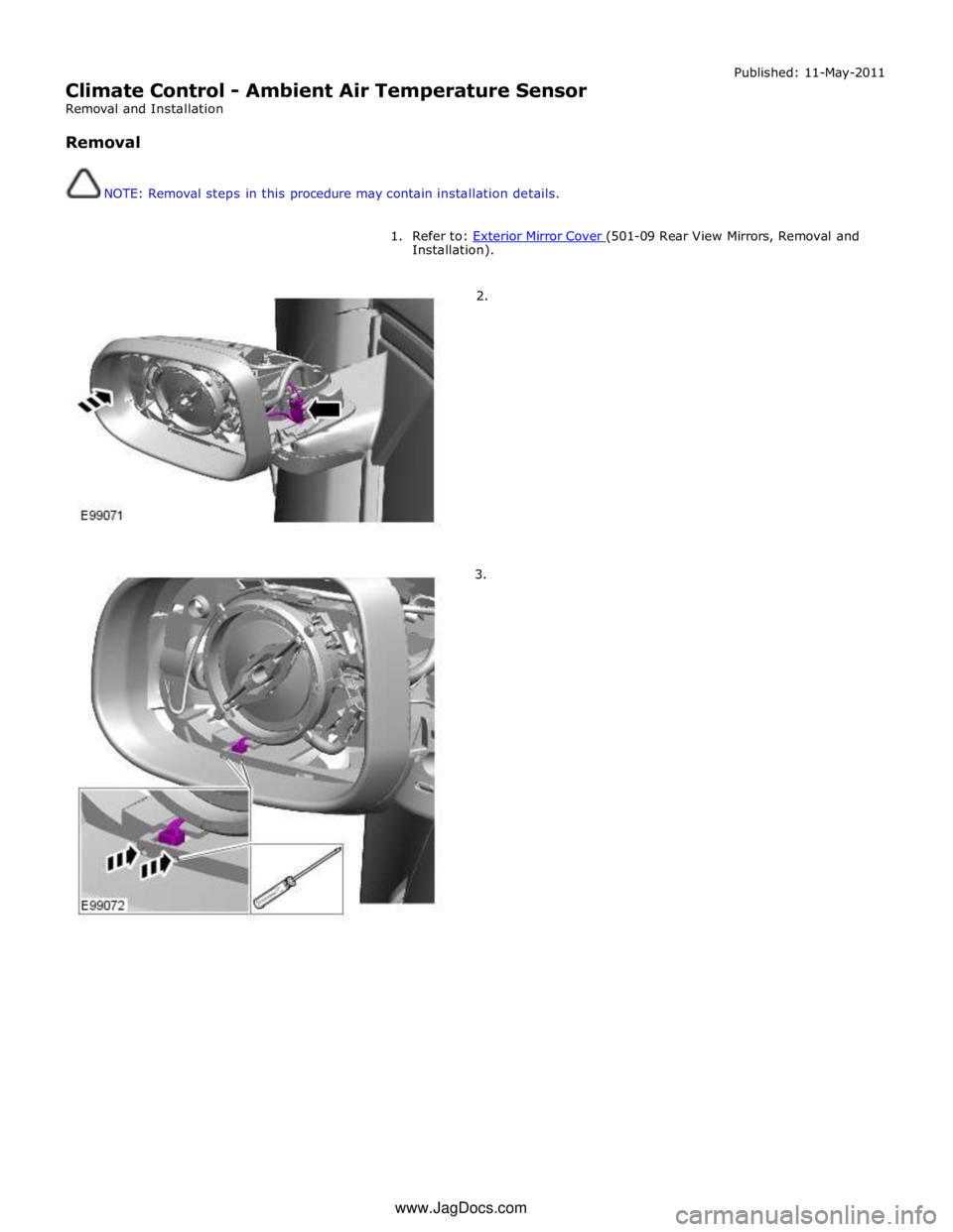
NOTE: Removal steps in this procedure may contain installation details. Published: 11-May-2011
1. Refer to: Exterior Mirror Cover (501-09 Rear View Mirrors, Removal and Installation).
2.
3. www.JagDocs.com
Page 1827 of 3039
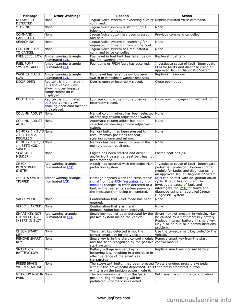
NO SPEECH
DETECTED None
Jaguar Voice system is expecting a voice
command . Repeat required voice command. STORING None
Jaguar Voice system is storing input telephone information. None COMMAND
CANCELLED None
Jaguar Voice button has been pressed
and held. Previous command cancelled. SEARCHING None
Jaguar Voice system is searching for requested information from phone book. None HOLD BUTTON TO CANCEL None
Jaguar Voice system has requested a
command to be cancelled. None FUEL LEVEL LOW
Amber warning triangle
illuminated LCD. Fuel level in fuel tank has fallen below
low fuel warning limit. Replenish fuel tank. FUEL PUMP
SYSTEM FAULT Amber warning triangle
illuminated LCD. Fuel pump or FPDM fault has occurred.
Investigate cause of fault. Interrogate
ECM for faults and diagnose using an approved Jaguar Diagnostic System. WASHER FLUID
LOW Amber warning triangle
illuminated LCD. Fluid level has fallen below low level
switch in windshield washer reservoir. Replenish reservoir. DOOR OPEN
Red text is illuminated in
LCD and vehicle view Door is open or incorrectly closed. Close open door. showing open luggage
compartment lid is
displayed. BOOT OPEN
Red text is illuminated in
LCD and vehicle view Luggage compartment lid is open or incorrectly closed. Close open luggage compartment lid. showing open door location
is displayed. COLUMN ADJUST None
Manual column adjust has been selected
on steering column adjustment switch. None COLUMN ADJUST
AUTO None
Automatic column adjust has been
selected on steering column adjustment
switch. None MEMORY 1 / 2 / 3 / 4 SETTINGS
RECALLED None
Memory button has been pressed to
recall memory positions for seat, steering column and mirrors. None MEMORY 1 / 2 / 3 / 4 SETTINGS
SAVED None
Memory has been saved for one of the
memory button positions. None SEAT BELT
MINDER None
Engine has been started and driver
and/or front passenger seat belt has not
been fastened. Fasten seat belt(s). CHECK
PEDESTRIAN
SYSTEM Red warning triangle
illuminated in LCD. A fault has occurred with the pedestrian
protection system. Investigate cause of fault. Interrogate
pedestrian protection system control
module for faults and diagnose using
an approved Jaguar Diagnostic System. INERTIA SWITCH TRIPPED Amber warning triangle
illuminated LCD. Message appears when the crash status
signal from the RCM (restraints control
module) changes to crash detected or a
fault in the restraints system prevents
the message from being transmitted. RCM can be rest with an ignition on/off cycle. If fault has occurred, then
investigate cause of fault and
interrogate the RCM for faults and diagnose using an approved Jaguar
Diagnostic System. VALET MODE None
Confirmation that valet mode has been
entered. None VEHICLE ARMED None
Confirmation that alarm and
immobilization has been achieved. None SMART KEY NOT
FOUND PLEASE
INSERT IN SLOT Red warning triangle
illuminated in LCD. Smart key has not been detected by the
passive system inside the vehicle. Smart key not present in vehicle. May
be caused by a flat smart key battery.
Replace internal battery in smart key.
May also be due to a communications problem. CHECK SMART
KEY None The smart key detected is not the
correct smart key for the vehicle. Use the correct smart key coded to the
vehicle. REMOVE SMART
KEY None
Smart key is in the start control module
and has been recognized by the passive
start system. Remove smart key from the start
control module. SMART KEY
BATTERY LOW None
Battery voltage in smart key is
becoming low, resulting in a decrease in
effective range of the smart key
transmitter. Replace smart key internal battery. PRESS BRAKE
WHEN STARTING None The stop/start button has been pressed
without the brake pedal depressed. This
will turn on the ignition power mode 6. To start engine, press brake pedal,
then press stop/start button. GEARBOX NOT IN
PARK None The transmission is not in the 'park'
position. Engine starting will be prohibited until 'park' is selected. Put transmission in the park position. www.JagDocs.com
Page 1831 of 3039
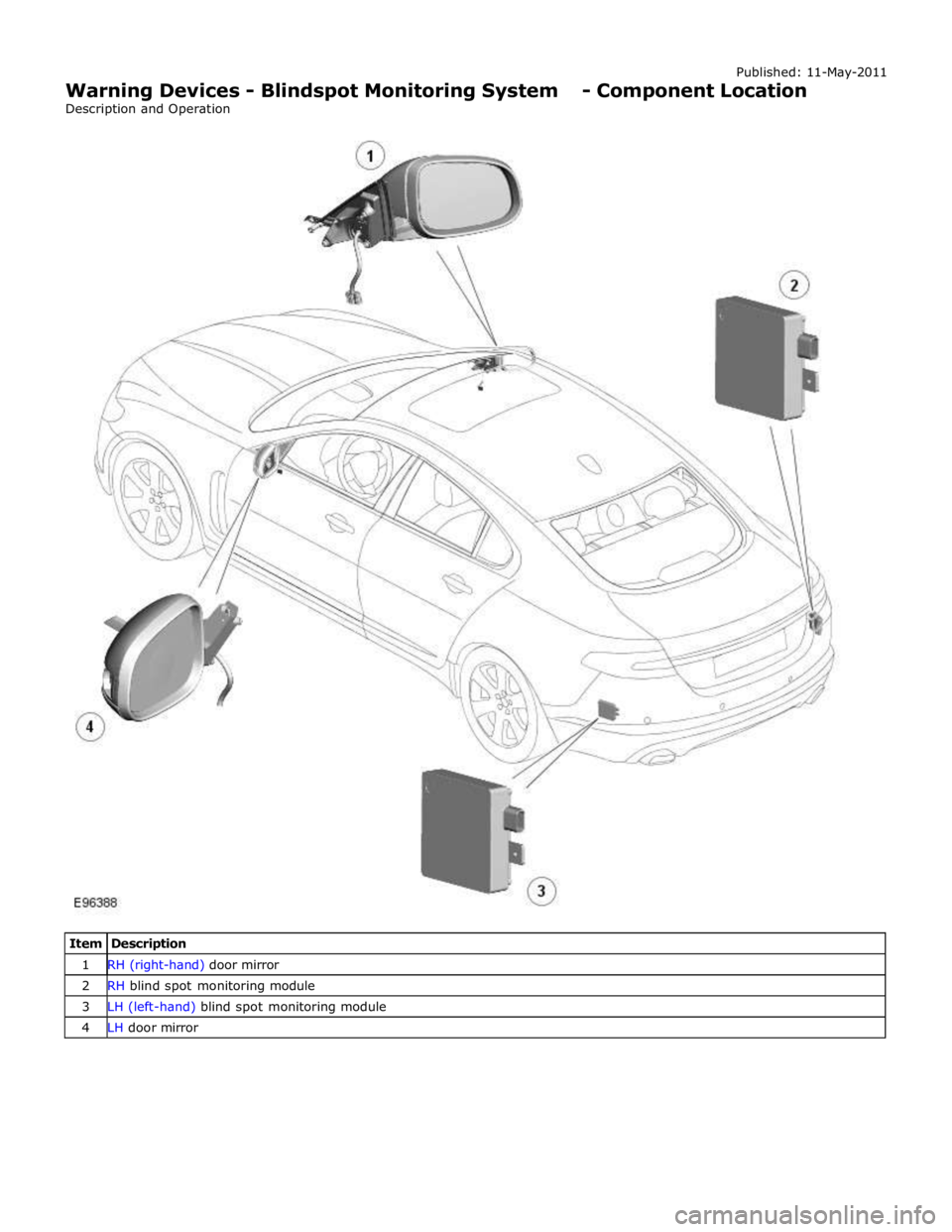
1 RH (right-hand) door mirror 2 RH blind spot monitoring module 3 LH (left-hand) blind spot monitoring module 4 LH door mirror
Page 1832 of 3039

Warning Devices - Blindspot Monitoring System - Overview
Description and Operation
OVERVIEW Published: 11-May-2011
Eliminating blind spots is a major element in vehicle body design, but because of the structural requirements of B, C and D
posts, blind spots cannot be entirely eliminated. Statistics show that some accidents are directly attributable to drivers moving
across into the path of overtaking vehicles that have not been seen in conventional mirrors. New mirror designs have improved
the situation, but by remotely covering areas that cannot be seen either directly or by the vehicle mirrors, have led to the
introduction of a radar-based blind spot monitoring system.
The blind spot monitoring system comprises:
LH (left-hand) Blind spot monitoring sensor
RH (right-hand) Blind spot monitoring sensor
LH door mirror RH door mirror
The system uses two radar modules operating at a frequency of 24 GHz and each combining the radar face and electronic
module in a single unit. The modules are located behind the rear bumper surface, symmetrically, one on each side of the car
behind the rear wheels. They are side facing and inclined rearwards at an angle of 16 degrees, which is dictated by the shape
at the rear of the vehicle. Each module is calibrated to detect a vehicle in the driver’s blind spot. Once a vehicle is detected
the module illuminates an amber warning ‘alert icon’ LED (light emitting diode) in the relevant exterior door mirror. If there is a
fault or blockage with the blind spot monitoring system an amber warning indicator dot LED is displayed in the exterior mirror and the message ‘blind spot monitoring not available’ is displayed in the instrument cluster message center.
When the system initiates, it performs a self-check, during which the warning icons in the mirrors illuminate alternately for a
short period of time. Each module does a left/right determination check when the ignition is switched on. Each mirror has a
different circuit configuration so that the modules can determine which mirror they are connected to. If a module detects the
wrong mirror it will go into a fault condition.
The blind spot monitoring modules receive vehicle speed on the medium speed CAN (controller area network) and are inactive
until the vehicle reaches 16kph (10mph). Each blind spot monitor module emits a radar field greater than the blind spot area.
Each Blind Spot Monitor module emits a radar field greater than the blind spot area. The actual blind spot area is calibrated
into the module during its manufacture.
CAUTION: The blind spot monitoring system is designed as a driver aid not a safety device. The driver should always
exercise due care and attention whilst driving. www.JagDocs.com