Page 1129 of 3039

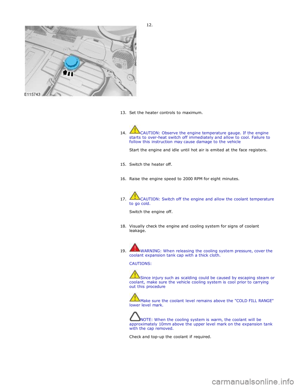
12.
13.
Set the heater controls to maximum.
14. CAUTION: Observe the engine temperature gauge. If the engine
starts to over-heat switch off immediately and allow to cool. Failure to
follow this instruction may cause damage to the vehicle
Start the engine and idle until hot air is emited at the face registers.
15. Switch the heater off.
16. Raise the engine speed to 2000 RPM for eight minutes.
17. CAUTION: Switch off the engine and allow the coolant temperature
to go cold.
Switch the engine off.
18. Visually check the engine and cooling system for signs of coolant
leakage.
19. WARNING: When releasing the cooling system pressure, cover the
coolant expansion tank cap with a thick cloth.
CAUTIONS:
Since injury such as scalding could be caused by escaping steam or
coolant, make sure the vehicle cooling system is cool prior to carrying
out this procedure
Make sure the coolant level remains above the "COLD FILL RANGE"
lower level mark.
NOTE: When the cooling system is warm, the coolant will be
approximately 10mm above the upper level mark on the expansion tank
with the cap removed.
Check and top-up the coolant if required.
Page 1131 of 3039
Filling
1. Refer to: Radiator Splash Shield (501-02 Front End Body Panels, Removal and Installation).
2. Lower the vehicle.
3.
4. CAUTION: Anti-freeze concentration must be maintained at 50%.
Fill the cooling system, keeping coolant to the upper level mark of the
expansion tank until a steady stream of coolant is seen running from the
coolant hose bleed point.
Page 1132 of 3039
5.
Continue to fill the coolant until the maximum level
is reached.
6. Set the heater controls to maximum.
7. Start engine and increase speed to 2000 rpm for 2 minutes.
8.
Continue to top-up with coolant with engine idling until hot air is
emitted from face vents.
When hot air is emitted from the vents, switch the heater off. Go
to Step 10.
9. If no hot air is emitted, turn the engine off for 10 seconds and the start
the engine and return to Step 7.
10. CAUTION: Correct installation of the Coolant
expansion tank cap can be obtained by tightening the cap
until an audible click is heard.
Continue to fill the coolant until the maximum level is
reached.
11. Switch the heater off.
12. Raise the engine speed to 2000 rpm for eight minutes.
13. Switch the engine off and allow to cool.
14. Visually check the engine and cooling system for signs of coolant
leakage.
Page 1133 of 3039
15. WARNING: When releasing the cooling system pressure, cover the
coolant expansion tank cap with a thick cloth.
CAUTIONS:
Since injury such as scalding could be caused by escaping steam or
coolant, make sure the vehicle cooling system is cool prior to carrying
out this procedure.
Make sure the coolant level remains above the "COLD FILL RANGE"
lower level mark.
NOTE: When the cooling system is warm, the coolant will be
approximately 10mm above the upper level mark on the expansion tank
with the cap removed.
Check and top-up the coolant if required.
Page 1138 of 3039

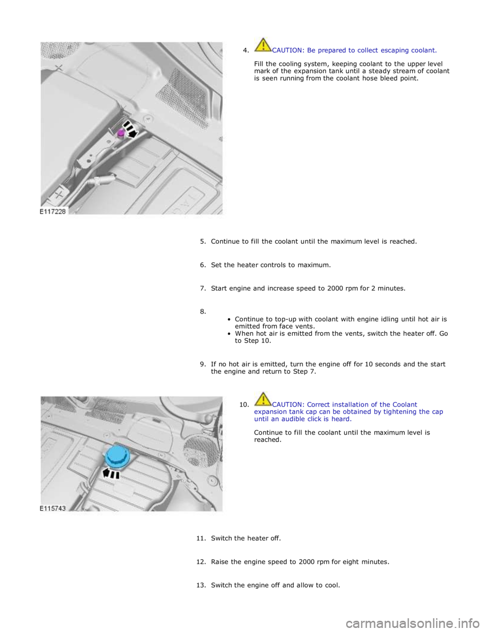
4. CAUTION: Be prepared to collect escaping coolant.
Fill the cooling system, keeping coolant to the upper level
mark of the expansion tank until a steady stream of coolant
is seen running from the coolant hose bleed point.
5. Continue to fill the coolant until the maximum level is reached.
6. Set the heater controls to maximum.
7. Start engine and increase speed to 2000 rpm for 2 minutes.
8.
Continue to top-up with coolant with engine idling until hot air is
emitted from face vents.
When hot air is emitted from the vents, switch the heater off. Go
to Step 10.
9. If no hot air is emitted, turn the engine off for 10 seconds and the start
the engine and return to Step 7.
10. CAUTION: Correct installation of the Coolant
expansion tank cap can be obtained by tightening the cap
until an audible click is heard.
Continue to fill the coolant until the maximum level is
reached.
11. Switch the heater off.
12. Raise the engine speed to 2000 rpm for eight minutes.
13. Switch the engine off and allow to cool.
Page 1139 of 3039
14. Visually check the engine and cooling system for signs of coolant
leakage.
15. WARNING: When releasing the cooling system pressure, cover the
coolant expansion tank cap with a thick cloth.
CAUTIONS:
Since injury such as scalding could be caused by escaping steam or
coolant, make sure the vehicle cooling system is cool prior to carrying
out this procedure.
Make sure the coolant level remains above the "COLD FILL RANGE"
lower level mark.
NOTE: When the cooling system is warm, the coolant will be
approximately 10mm above the upper level mark on the expansion tank
with the cap removed.
Check and top-up the coolant system as required when cool.
16. Refer to: Air Deflector (501-02 Front End Body Panels, Removal and Installation).
17. Refer to: Radiator Splash Shield (501-02 Front End Body Panels, Removal and Installation).
18. Refer to: Secondary Bulkhead Center Panel (501-02 Front End Body Panels, Removal and Installation).
Page 1144 of 3039
Installation 5. CAUTION: Note the fitted position of the component
prior to removal.
NOTES:
Do not disassemble further if the component is
removed for access only.
Make sure that the component is installed to the
position noted on removal.
1. To install, reverse the removal procedure.
2. Fill the cooling system to the upper level mark of the coolant expansion
tank.
Page 1187 of 3039

Published: 11-May-2011
Fuel Charging and Controls - V8 S/C 5.0L Petrol - Fuel Charging and Controls
Diagnosis and Testing
Principles of Operation
For a detailed description of the fuel charging and controls system and operation, refer to the relevant Description and
Operation section of the workshop manual. REFER to:
Fuel Charging and Controls (303-04D Fuel Charging and Controls - V8 5.0L Petrol, Description and Operation), Fuel Charging and Controls (303-04D Fuel Charging and Controls - V8 5.0L Petrol, Description and Operation), Fuel Charging and Controls (303-04D Fuel Charging and Controls - V8 5.0L Petrol, Description and Operation), Fuel Charging and Controls (303-04E Fuel Charging and Controls - V8 S/C 5.0L Petrol, Description and Operation), Fuel Charging and Controls (303-04E Fuel Charging and Controls - V8 S/C 5.0L Petrol, Description and Operation), Fuel Charging and Controls (303-04E Fuel Charging and Controls - V8 S/C 5.0L Petrol, Description and Operation).
Inspection and Verification
CAUTION: Diagnosis by substitution from a donor vehicle is NOT acceptable. Substitution of control modules does not
guarantee confirmation of a fault and may also cause additional faults in the vehicle being checked and/or the donor vehicle.
NOTE: Check and rectify basic faults before beginning diagnostic routines involving pinpoint tests.
1. Verify the customer concern.
2. Visually inspect for obvious signs of mechanical or electrical damage.
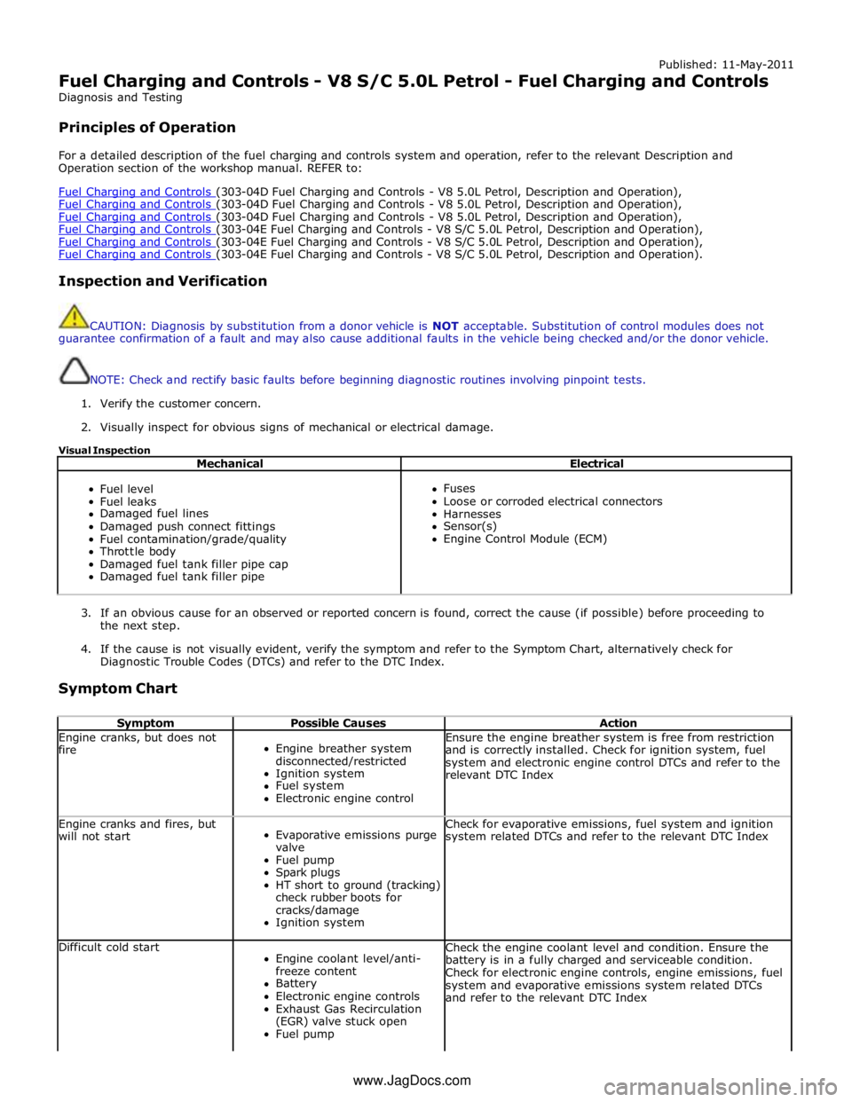
Visual Inspection
Mechanical Electrical
Fuel level
Fuel leaks
Damaged fuel lines
Damaged push connect fittings
Fuel contamination/grade/quality
Throttle body
Damaged fuel tank filler pipe cap
Damaged fuel tank filler pipe
Fuses
Loose or corroded electrical connectors
Harnesses
Sensor(s)
Engine Control Module (ECM)
3. If an obvious cause for an observed or reported concern is found, correct the cause (if possible) before proceeding to
the next step.
4. If the cause is not visually evident, verify the symptom and refer to the Symptom Chart, alternatively check for
Diagnostic Trouble Codes (DTCs) and refer to the DTC Index.
Symptom Chart
Symptom Possible Causes Action Engine cranks, but does not
fire
Engine breather system
disconnected/restricted
Ignition system
Fuel system
Electronic engine control Ensure the engine breather system is free from restriction
and is correctly installed. Check for ignition system, fuel
system and electronic engine control DTCs and refer to the
relevant DTC Index Engine cranks and fires, but
will not start
Evaporative emissions purge
valve
Fuel pump
Spark plugs
HT short to ground (tracking)
check rubber boots for
cracks/damage
Ignition system Check for evaporative emissions, fuel system and ignition
system related DTCs and refer to the relevant DTC Index Difficult cold start
Engine coolant level/anti-
freeze content
Battery
Electronic engine controls
Exhaust Gas Recirculation
(EGR) valve stuck open
Fuel pump Check the engine coolant level and condition. Ensure the
battery is in a fully charged and serviceable condition.
Check for electronic engine controls, engine emissions, fuel
system and evaporative emissions system related DTCs
and refer to the relevant DTC Index www.JagDocs.com