2010 JAGUAR XFR automatic transmission fluid
[x] Cancel search: automatic transmission fluidPage 1434 of 3039

solenoid valve in the valve housing directs hydraulic pressure to the lock cylinder, which moves the piston within the cylinder
and releases the park lock pawl at the rear of the transmission by means of a connecting rod. The solenoid on the lock cylinder
is energized and locks the cylinder piston in the unlocked position. Additional locking of the piston is achieved with ball
catches within the lock cylinder.
When park is selected, the solenoid on the lock cylinder is de-energized, the ball catches are released and the piston is free to
move in the lock cylinder. The solenoid in the valve housing is also de-energized. The spring loaded parking disc pulls the
cylinder piston in the park direction which allows the park disc to move on its mounting. This movement is transferred via the
connecting rod to parking pawl, which is engaged in the park lock gear.
If an electrical failure occurs, the park lock can be manually released by means of an emergency park release lever located in
the floor console. The lever is connected to the parking disc by a cable and allows the park lock to be released manually. For
additional information, refer to 307-05B Automatic Transmission/Transaxle External Controls.
TRANSMISSION CONTROL MODULE
The TCM is an integral part of the Mechatronic valve block which is located at the bottom of the transmission, within the fluid pan. The TCM is the main controlling component of the transmission.
The TCM processes signals from the transmission speed and temperature sensors, ECM and other vehicle systems. From the received signal inputs and pre-programmed data, the module calculates the correct gear, torque converter clutch setting and
optimum pressure settings for gear shift and lock-up clutch control.
Page 1435 of 3039
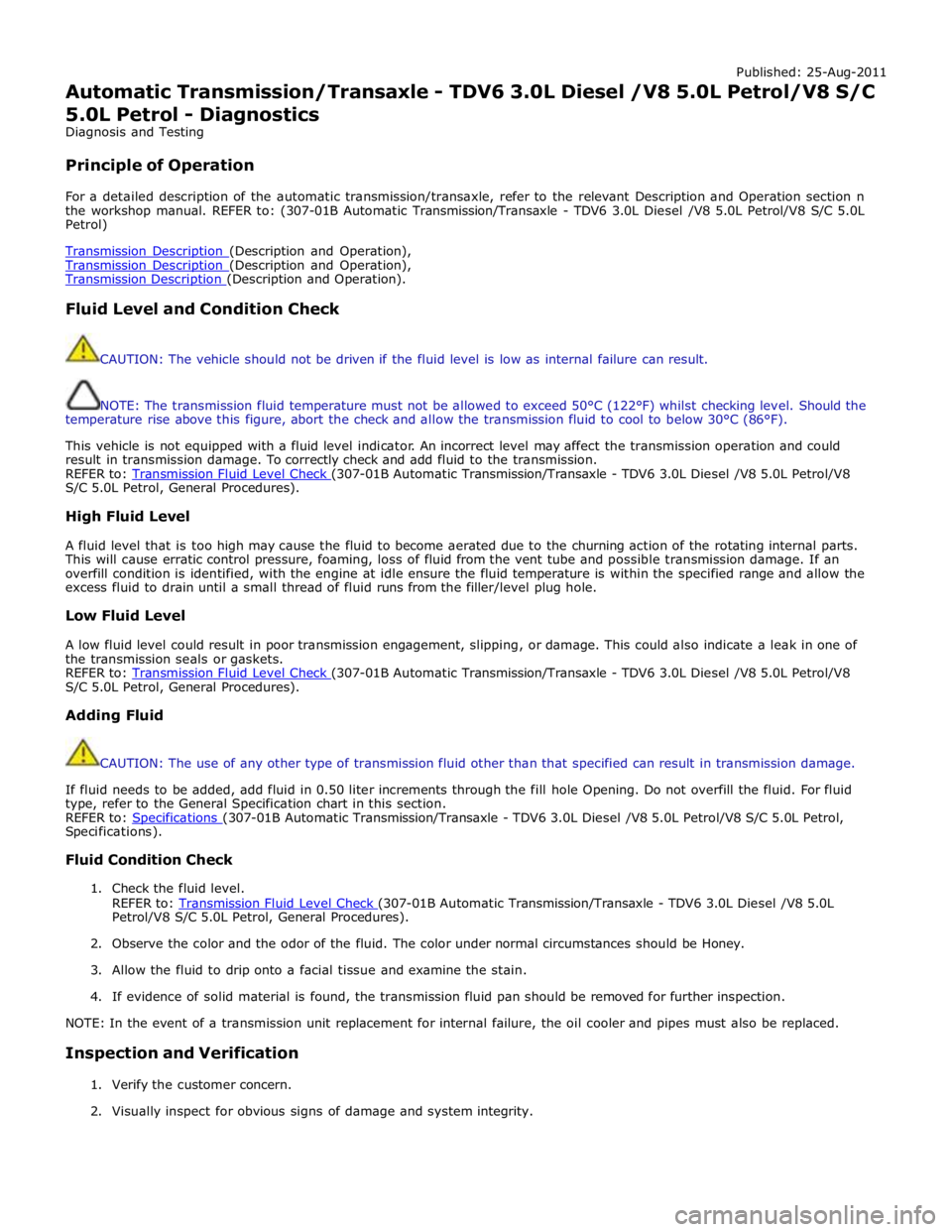
Published: 25-Aug-2011
Automatic Transmission/Transaxle - TDV6 3.0L Diesel /V8 5.0L Petrol/V8 S/C 5.0L Petrol - Diagnostics
Diagnosis and Testing
Principle of Operation
For a detailed description of the automatic transmission/transaxle, refer to the relevant Description and Operation section n
the workshop manual. REFER to: (307-01B Automatic Transmission/Transaxle - TDV6 3.0L Diesel /V8 5.0L Petrol/V8 S/C 5.0L
Petrol)
Transmission Description (Description and Operation), Transmission Description (Description and Operation), Transmission Description (Description and Operation).
Fluid Level and Condition Check
CAUTION: The vehicle should not be driven if the fluid level is low as internal failure can result.
NOTE: The transmission fluid temperature must not be allowed to exceed 50°C (122°F) whilst checking level. Should the
temperature rise above this figure, abort the check and allow the transmission fluid to cool to below 30°C (86°F).
This vehicle is not equipped with a fluid level indicator. An incorrect level may affect the transmission operation and could
result in transmission damage. To correctly check and add fluid to the transmission.
REFER to: Transmission Fluid Level Check (307-01B Automatic Transmission/Transaxle - TDV6 3.0L Diesel /V8 5.0L Petrol/V8 S/C 5.0L Petrol, General Procedures).
High Fluid Level
A fluid level that is too high may cause the fluid to become aerated due to the churning action of the rotating internal parts.
This will cause erratic control pressure, foaming, loss of fluid from the vent tube and possible transmission damage. If an
overfill condition is identified, with the engine at idle ensure the fluid temperature is within the specified range and allow the
excess fluid to drain until a small thread of fluid runs from the filler/level plug hole.
Low Fluid Level
A low fluid level could result in poor transmission engagement, slipping, or damage. This could also indicate a leak in one of
the transmission seals or gaskets.
REFER to: Transmission Fluid Level Check (307-01B Automatic Transmission/Transaxle - TDV6 3.0L Diesel /V8 5.0L Petrol/V8 S/C 5.0L Petrol, General Procedures).
Adding Fluid
CAUTION: The use of any other type of transmission fluid other than that specified can result in transmission damage.
If fluid needs to be added, add fluid in 0.50 liter increments through the fill hole Opening. Do not overfill the fluid. For fluid
type, refer to the General Specification chart in this section.
REFER to: Specifications (307-01B Automatic Transmission/Transaxle - TDV6 3.0L Diesel /V8 5.0L Petrol/V8 S/C 5.0L Petrol, Specifications).
Fluid Condition Check
1. Check the fluid level.
REFER to: Transmission Fluid Level Check (307-01B Automatic Transmission/Transaxle - TDV6 3.0L Diesel /V8 5.0L Petrol/V8 S/C 5.0L Petrol, General Procedures).
2. Observe the color and the odor of the fluid. The color under normal circumstances should be Honey.
3. Allow the fluid to drip onto a facial tissue and examine the stain.
4. If evidence of solid material is found, the transmission fluid pan should be removed for further inspection.
NOTE: In the event of a transmission unit replacement for internal failure, the oil cooler and pipes must also be replaced.
Inspection and Verification
1. Verify the customer concern.
2. Visually inspect for obvious signs of damage and system integrity.
Page 1436 of 3039
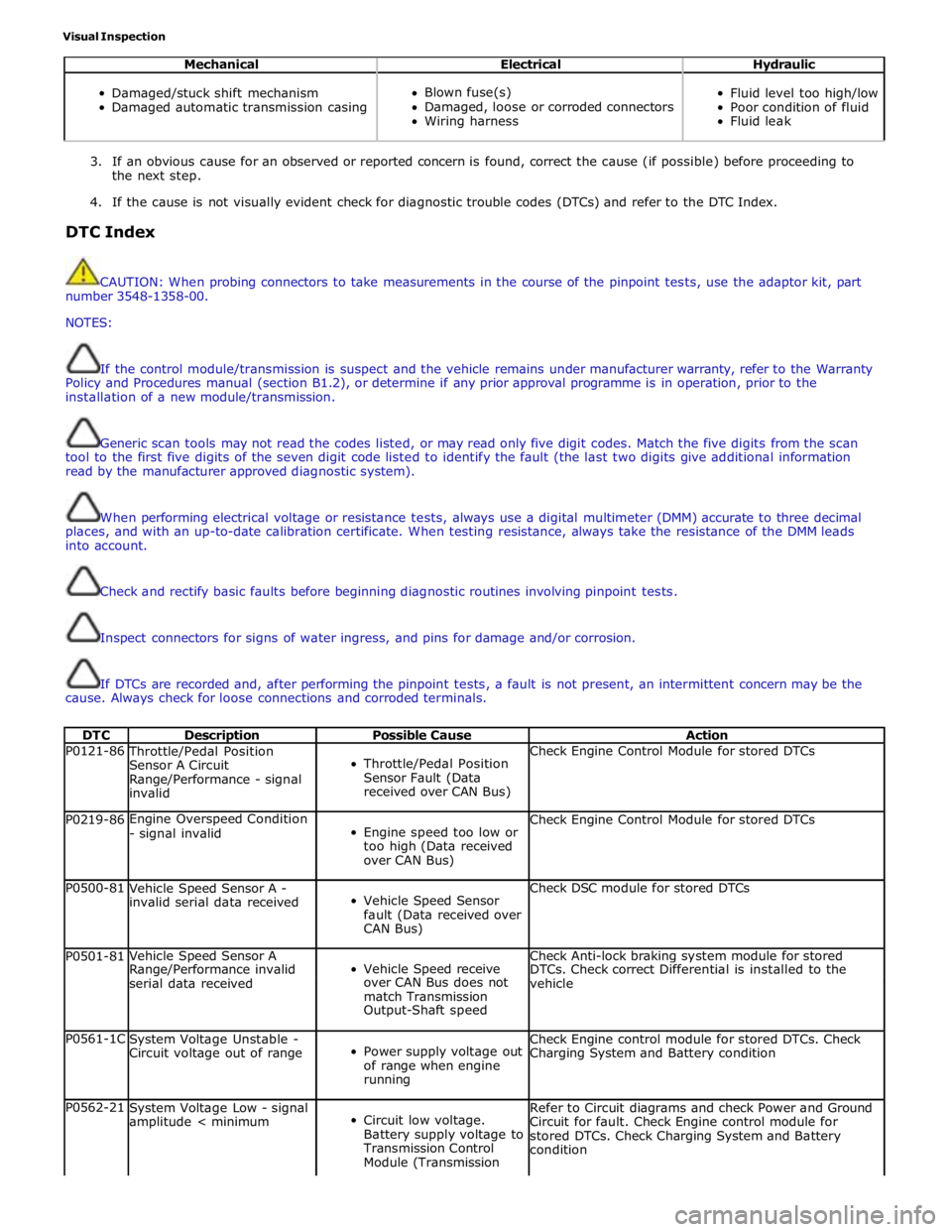
Visual Inspection
Mechanical Electrical Hydraulic
Damaged/stuck shift mechanism
Damaged automatic transmission casing
Blown fuse(s)
Damaged, loose or corroded connectors
Wiring harness
Fluid level too high/low
Poor condition of fluid
Fluid leak
3. If an obvious cause for an observed or reported concern is found, correct the cause (if possible) before proceeding to
the next step.
4. If the cause is not visually evident check for diagnostic trouble codes (DTCs) and refer to the DTC Index.
DTC Index
CAUTION: When probing connectors to take measurements in the course of the pinpoint tests, use the adaptor kit, part
number 3548-1358-00.
NOTES:
If the control module/transmission is suspect and the vehicle remains under manufacturer warranty, refer to the Warranty
Policy and Procedures manual (section B1.2), or determine if any prior approval programme is in operation, prior to the
installation of a new module/transmission.
Generic scan tools may not read the codes listed, or may read only five digit codes. Match the five digits from the scan
tool to the first five digits of the seven digit code listed to identify the fault (the last two digits give additional information
read by the manufacturer approved diagnostic system).
When performing electrical voltage or resistance tests, always use a digital multimeter (DMM) accurate to three decimal
places, and with an up-to-date calibration certificate. When testing resistance, always take the resistance of the DMM leads
into account.
Check and rectify basic faults before beginning diagnostic routines involving pinpoint tests.
Inspect connectors for signs of water ingress, and pins for damage and/or corrosion.
If DTCs are recorded and, after performing the pinpoint tests, a fault is not present, an intermittent concern may be the
cause. Always check for loose connections and corroded terminals.
DTC Description Possible Cause Action P0121-86 Throttle/Pedal Position
Sensor A Circuit
Range/Performance - signal
invalid
Throttle/Pedal Position
Sensor Fault (Data
received over CAN Bus) Check Engine Control Module for stored DTCs P0219-86 Engine Overspeed Condition
- signal invalid
Engine speed too low or
too high (Data received
over CAN Bus) Check Engine Control Module for stored DTCs P0500-81
Vehicle Speed Sensor A -
invalid serial data received
Vehicle Speed Sensor
fault (Data received over
CAN Bus) Check DSC module for stored DTCs P0501-81 Vehicle Speed Sensor A
Vehicle Speed receive Check Anti-lock braking system module for stored Range/Performance invalid DTCs. Check correct Differential is installed to the serial data received over CAN Bus does not
vehicle match Transmission Output-Shaft speed P0561-1C
System Voltage Unstable -
Circuit voltage out of range
Power supply voltage out
of range when engine
running Check Engine control module for stored DTCs. Check
Charging System and Battery condition P0562-21
System Voltage Low - signal
amplitude < minimum
Circuit low voltage.
Battery supply voltage to
Transmission Control
Module (Transmission Refer to Circuit diagrams and check Power and Ground
Circuit for fault. Check Engine control module for
stored DTCs. Check Charging System and Battery
condition
Page 1449 of 3039
Published: 11-May-2011
Automatic Transmission/Transaxle - TDV6 3.0L Diesel /V8 5.0L Petrol/V8 S/C 5.0L Petrol - Transmission Fluid Level Check
General Procedures
WARNINGS: Activation
Observe due care when draining, as the fluid can be very hot.
Observe due care when working near a hot exhaust system.
1.
The following steps must be observed before starting the
transmission fluid level check.
The vehicle must be on a horizontal ramp.
The parking brake must be applied.
The engine must be running for 2 minutes with the transmission
control switch (TCS) in the "P" position.
2. CAUTION: Make sure that the transmission fluid temperature is
below 30 degrees before starting the fluid level check.
Connect Jaguar approved diagnostic equipment to the vehicle.
3.
Apply, and hold, the footbrake.
Move the selector lever from 'P' through all the gear positions,
pausing in each gear position for 2-3 seconds and return to the
'P' position.
4. WARNING: Make sure to support the vehicle with axle stands.
Raise and support the vehicle.
5. Refer to: Air Deflector (501-02 Front End Body Panels, Removal and Installation).
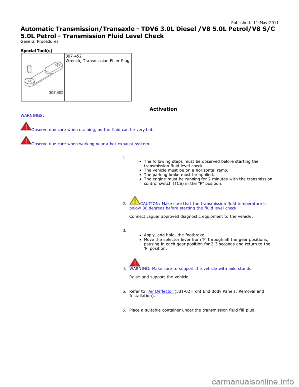
6. Place a suitable container under the transmission fluid fill plug. 307-452
Wrench, Transmission Filler Plug Special Tool(s)
Page 1453 of 3039
Published: 11-May-2011
Automatic Transmission/Transaxle - TDV6 3.0L Diesel /V8 5.0L Petrol/V8 S/C 5.0L Petrol - Transmission Fluid Drain and Refill
General Procedures
WARNINGS:
Observe due care when draining, as the fluid can be very hot.
Observe due care when working near a hot exhaust system.
1. WARNING: Make sure to support the vehicle with axle stands.
Raise and support the vehicle.
2. Refer to: Air Deflector (501-02 Front End Body Panels, Removal and Installation).
3. Place a container under the transmission.
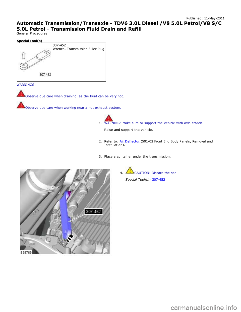
4. CAUTION: Discard the seal.
Special Tool(s): 307-452 307-452
Wrench, Transmission Filler Plug Special Tool(s)
Page 1463 of 3039
Published: 11-May-2011
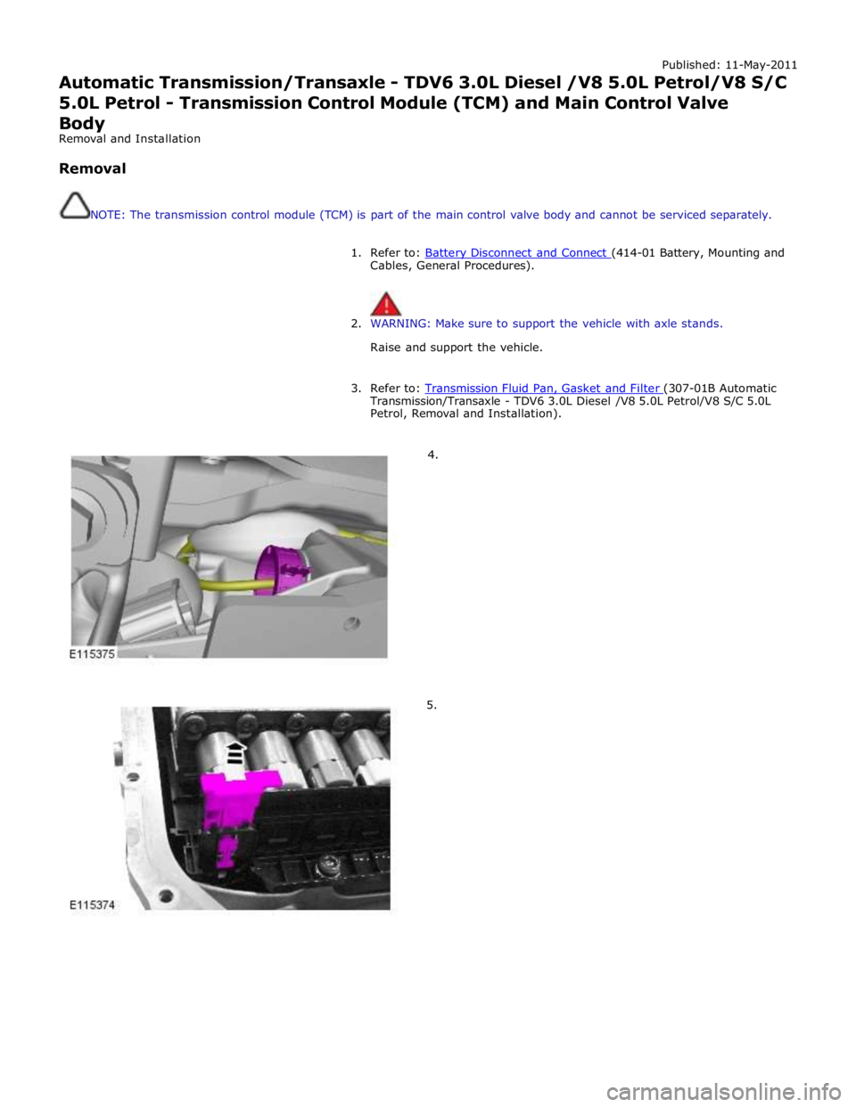
Automatic Transmission/Transaxle - TDV6 3.0L Diesel /V8 5.0L Petrol/V8 S/C 5.0L Petrol - Transmission Control Module (TCM) and Main Control Valve
Body
Removal and Installation
Removal
NOTE: The transmission control module (TCM) is part of the main control valve body and cannot be serviced separately.
1. Refer to: Battery Disconnect and Connect (414-01 Battery, Mounting and Cables, General Procedures).
2. WARNING: Make sure to support the vehicle with axle stands.
Raise and support the vehicle.
3. Refer to: Transmission Fluid Pan, Gasket and Filter (307-01B Automatic Transmission/Transaxle - TDV6 3.0L Diesel /V8 5.0L Petrol/V8 S/C 5.0L
Petrol, Removal and Installation).
4.
5.
Page 1468 of 3039
Published: 11-May-2011
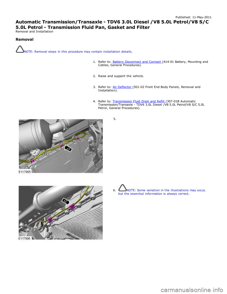
Automatic Transmission/Transaxle - TDV6 3.0L Diesel /V8 5.0L Petrol/V8 S/C 5.0L Petrol - Transmission Fluid Pan, Gasket and Filter
Removal and Installation
Removal
NOTE: Removal steps in this procedure may contain installation details.
1. Refer to: Battery Disconnect and Connect (414-01 Battery, Mounting and Cables, General Procedures).
2. Raise and support the vehicle.
3. Refer to: Air Deflector (501-02 Front End Body Panels, Removal and Installation).
4. Refer to: Transmission Fluid Drain and Refill (307-01B Automatic Transmission/Transaxle - TDV6 3.0L Diesel /V8 5.0L Petrol/V8 S/C 5.0L
Petrol, General Procedures).
5.
6. NOTE: Some variation in the illustrations may occur,
but the essential information is always correct.
Page 1471 of 3039
Published: 12-Sep-2011
Automatic Transmission/Transaxle - TDV6 3.0L Diesel /V8 5.0L Petrol/V8 S/C 5.0L Petrol - Transmission, Transmission Fluid Cooler and Transmission Fluid
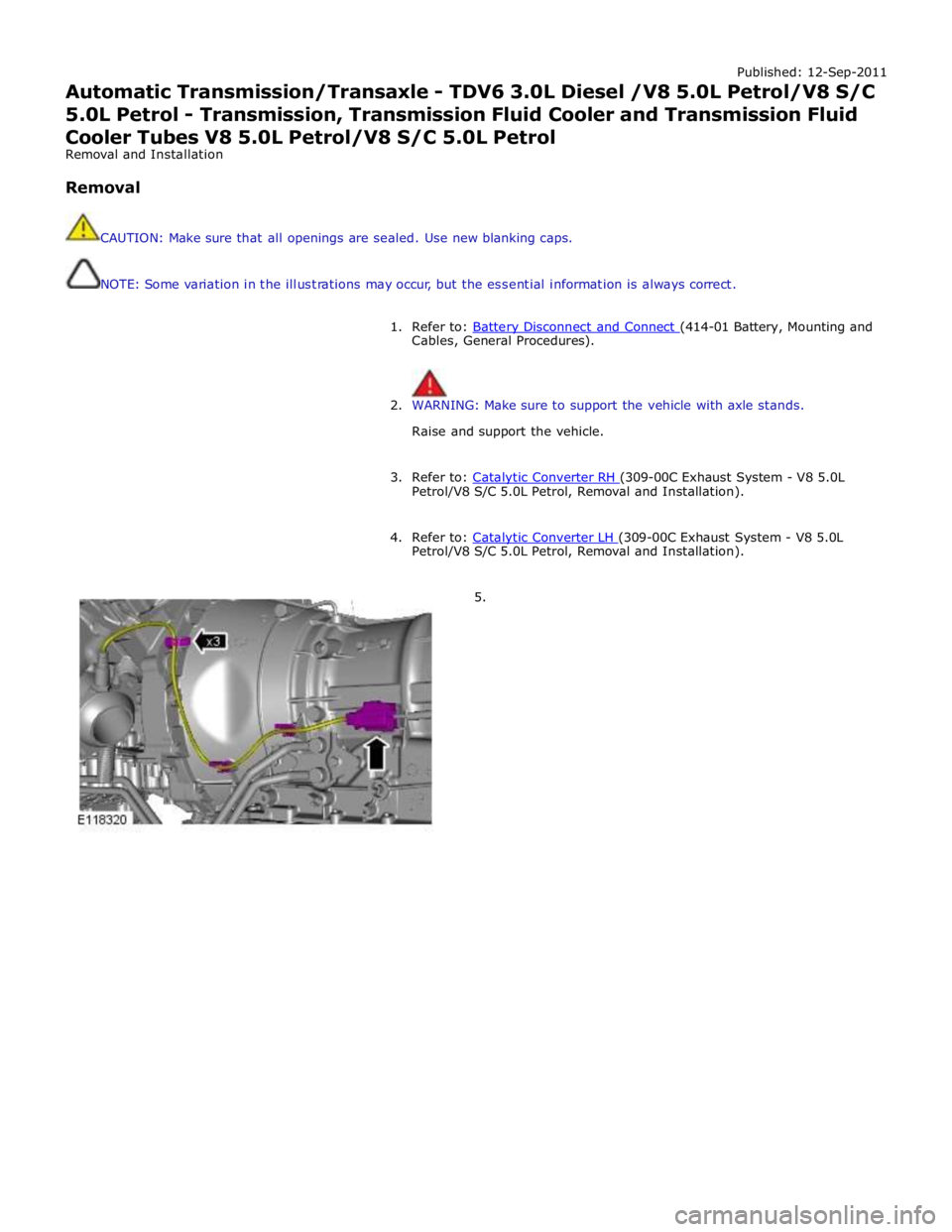
Cooler Tubes V8 5.0L Petrol/V8 S/C 5.0L Petrol
Removal and Installation
Removal
CAUTION: Make sure that all openings are sealed. Use new blanking caps.
NOTE: Some variation in the illustrations may occur, but the essential information is always correct.
1. Refer to: Battery Disconnect and Connect (414-01 Battery, Mounting and Cables, General Procedures).
2. WARNING: Make sure to support the vehicle with axle stands.
Raise and support the vehicle.
3. Refer to: Catalytic Converter RH (309-00C Exhaust System - V8 5.0L Petrol/V8 S/C 5.0L Petrol, Removal and Installation).
4. Refer to: Catalytic Converter LH (309-00C Exhaust System - V8 5.0L Petrol/V8 S/C 5.0L Petrol, Removal and Installation).
5.