2010 JAGUAR XFR Module control functions
[x] Cancel search: Module control functionsPage 1791 of 3039
Instrument Cluster - Instrument Cluster
Diagnosis and Testing
Principles of Operation Published: 22-Mar-2013
For a detailed description of the Instrument Cluster, refer to the relevant Description and Operation sections in the workshop
manual. REFER to: (413-01 Instrument Cluster)
Instrument Cluster (Description and Operation), Instrument Cluster (Description and Operation), Instrument Cluster (Description and Operation).
Inspection and Verification
CAUTION: Diagnosis by substitution from a donor vehicle is NOT acceptable. Substitution of control modules does not
guarantee confirmation of a fault, and may also cause additional faults in the vehicle being tested and/or the donor vehicle.
1. Verify the customer concern.
2. Visually inspect for obvious signs of damage and system integrity.
Visual Inspection
Mechanical Electrical
Fluid level(s)
Accessory installations
Fuse(s)
Wiring harness
Electrical connector(s)
Instrument cluster
Central Junction Box (CJB)
Engine Junction Box (EJB)
Driver Door Module (DDM)
Engine Control Module (ECM)
3. If an obvious cause for an observed or reported concern is found, correct the cause (if possible) before proceeding to
the next step.
4. If the cause is not visually evident, verify the symptom and refer to the Symptom Chart.
Symptom Chart
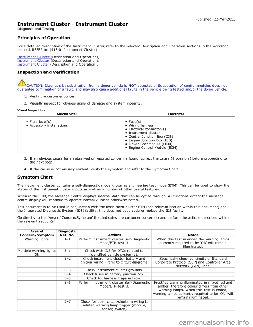
The instrument cluster contains a self-diagnostic mode known as engineering test mode (ETM). This can be used to show the
status of the instrument cluster inputs as well as a number of other useful features.
When in the ETM, the Message Centre displays internal data that can be cycled through. All functions except the message
centre display will continue to operate normally unless otherwise noted.
This document is to be used in conjunction with the instrument cluster ETM (see relevant section within this document) and
the Integrated Diagnostic System (IDS) facility; this does not supersede or replace the IDS facility.
Go directly to the 'Area of Concern/Symptom' that indicates the customer concern(s) and perform the actions described within
the relevant section(s):
Area of Concern/Symptom Diagnostic
Ref. No.
Actions
Notes Warning lights A-1
Perform instrument cluster Self-Diagnostic
Mode/ETM test 3. When this test is ended the warning lamps
currently required to be 'ON' will remain
illuminated. Multiple warning lights
'ON' B–1
Check with IDS for DTCs related to
identified vehicle system(s). . . B–2
Check instrument cluster battery and
ignition wiring - refer to circuit diagrams. Specifically check continuity of Standard
Corporate Protocol (SCP) and Controller Area
Network (CAN) lines. . B–3 Check instrument cluster grounds. . . B–4 Check fuses in battery junction box. . . B–5 Check for harness traps in facia. . . B–6
Perform instrument cluster Self-Diagnostic
Mode/ETM test 3. Frost/ice warning illuminated in mixed red and
amber; therefore colour differs from other
warning lamps. When this test is ended,
warning lamps currently required to be 'ON' will
remain illuminated. . B–7
Check for open circuit/shorts in wiring to
related warning lamp trigger (module,
sensor, switch). .
Page 1878 of 3039
Battery, Mounting and Cables - Battery and Cables - Overview
Description and Operation
OVERVIEW
Single Battery Vehicles Published: 18-Jun-2014
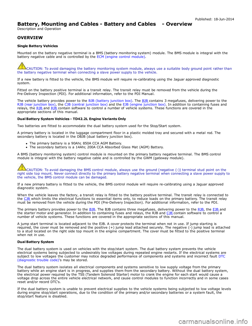
Mounted on the battery negative terminal is a BMS (battery monitoring system) module. The BMS module is integral with the
battery negative cable and is controlled by the ECM (engine control module).
CAUTION: To avoid damaging the battery monitoring system module, always use a suitable body ground point rather than
the battery negative terminal when connecting a slave power supply to the vehicle.
If a new battery is fitted to the vehicle, the BMS module will require re-calibrating using the Jaguar approved diagnostic
system.
Fitted on the battery positive terminal is a transit relay. The transit relay must be removed from the vehicle during the
Pre-Delivery Inspection (PDI). For additional information, refer to the PDI Manual.
The vehicle battery provides power to the BJB (battery junction box). The BJB contains 3 megafuses, delivering power to the RJB (rear junction box), the CJB (central junction box) and the EJB (engine junction box). In addition to containing fuses and
relays, the RJB and RJB contain software to control a number of vehicle systems. These functions are covered in the appropriate sections of this manual.
Dual Battery System Vehicles - TD42.2L Engine Variants Only
Two batteries are fitted to accommodate the dual battery system used for the Stop/Start system.
A primary battery is located in the luggage compartment floor in a plastic molded tray and secured with a metal rod. The
secondary battery is located in the DBJB (dual battery junction box).
The primary battery is a 90Ahr, 850A CCA AGM Battery.
The secondary battery is a 14Ahr, 200A CCA Absorbed Glass Mat (AGM) Battery.
A BMS (battery monitoring system) control module is mounted on the primary battery negative terminal. The BMS control
module is integral with the battery negative cable and is controlled by the GWM (gateway module).
CAUTION: To avoid damaging the BMS control module, always use the ground (negative (-)) terminal stud point on the
right side top mount. Never connect directly to the primary battery negative terminal when connecting a slave power supply to
the vehicle, the BMS control module can be damaged.
If a new primary battery is fitted to the vehicle, the BMS control module will require re-calibrating using a Jaguar approved
diagnostic system.
When the vehicle leaves the factory, a transit relay is fitted to the battery positive terminal. The transit relay is connected to
the CJB which limits the electrical functions to essential items only, to reduce loads on the primary battery. The transit relay must be removed from the vehicle during the PDI (Pre-Delivery Inspection). For additional information, refer to the PDI.
The primary battery provides power to the BJB. The BJB contains three megafuses, delivering power to the RJB, the EJB and the starter motor and generator. In addition to containing fuses and relays, the RJB and CJB contain software to control a number of vehicle systems. These functions are covered in the appropriate sections of this manual.
A jump start terminal is located adjacent to the EJB. A cover protects the terminal when not in use. If jump starting is
required, the cover must be removed and the positive (+) jump lead attached securely. The negative (-) jump lead is attached
to a stud located on the right side top mount in the engine compartment. The cover must be fitted to the positive terminal
when not in use.
Dual Battery System
The dual battery system is used on vehicles with the stop/start system. The dual battery system prevents the vehicle
electrical systems being subjected to undesirably low voltages during repeated engine restarts. If the electrical systems are
subject to low voltages the customer may notice degraded performance of components and systems and incorrect fault DTC
(diagnostic trouble code)'s may be stored.
The dual battery system isolates all electrical components and systems sensitive to low supply voltage from the primary
battery while an engine start is in progress, and supplies them from the secondary battery. Without the dual battery system,
the electrical power required by the TSS (Tandem Solenoid Starter) motor to crank the engine for each start would cause a
voltage drop across the entire vehicle electrical network, and cause control modules to function incorrectly and in some cases
reset and/or record DTC's.
If the dual battery system is unable to prevent electrical supplies to the vehicle systems being subjected to low voltage levels
during engine stop/start operations, due to the condition of the primary and/or secondary batteries or a system fault, the
stop/start feature is disabled.
Page 1886 of 3039
the secondary battery (if fitted) and passes through a grommet in the floorpan.
On new vehicles the primary battery positive terminal is fitted with a transit relay. The transit relay must removed using the
correct process detailed in the Pre Delivery Inspection (PDI) manual.
The battery negative terminal is fitted with a BMS control module. The control module is integral with the battery negative
cable and communicates with the GWM via a LIN bus connection. The battery condition information is passed to the GWM
which controls the generator output accordingly.
CAUTION: To avoid damage to the BMS control module, always use the body ground point in the engine compartment and
not the battery negative terminal when connecting a slave power supply.
Failure to use the recommended ground point will lead to the setting of a DTC. Incorrect information of battery condition will
be retained by the BMS control module due to the unmonitored current flow into the battery. The system will however,
recognize and compensate for the change in battery status after a period of time.
If a new battery is fitted, the BMS control module will require re-calibration using a Jaguar approved diagnostic system.
Replacement of the BMS control module requires no action as the control module will re-calibrate automatically.
SECONDARY BATTERY - DUAL BATTERY VEHICLES ONLY
The secondary battery is located in a tray on the next of the primary battery and is secured to the DBJB with a bracket. The
battery negative (-) terminal is connected via a cable to the vehicle body. The positive (+) terminal is connected by a cable to
the DBJB. The battery is vented via a tube which is connected with a T piece to the vent from the primary battery and passes
through a grommet in the floorpan.
The state of charge of the secondary battery is monitored by the Gateway Module (GWM).
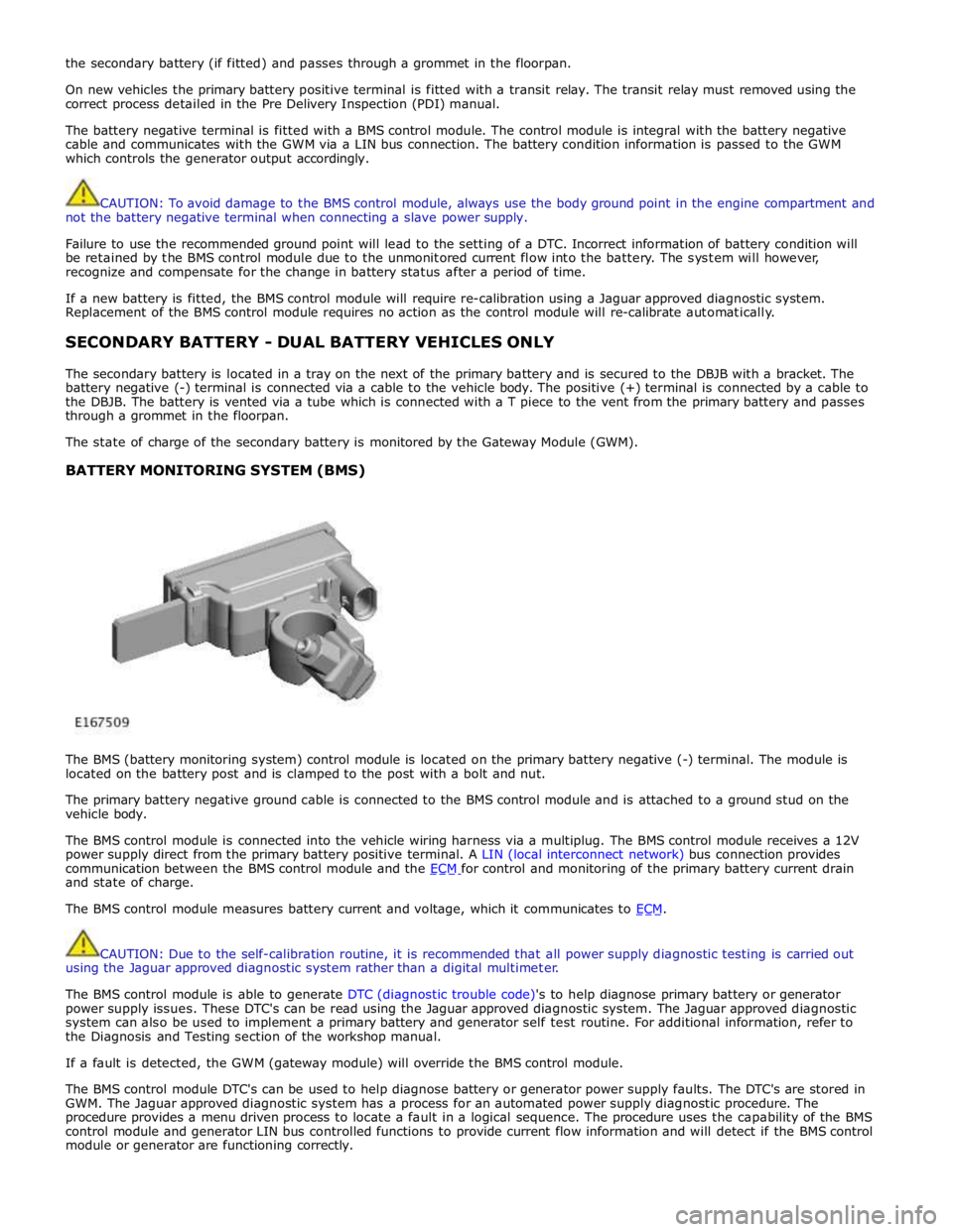
BATTERY MONITORING SYSTEM (BMS)
The BMS (battery monitoring system) control module is located on the primary battery negative (-) terminal. The module is
located on the battery post and is clamped to the post with a bolt and nut.
The primary battery negative ground cable is connected to the BMS control module and is attached to a ground stud on the
vehicle body.
The BMS control module is connected into the vehicle wiring harness via a multiplug. The BMS control module receives a 12V
power supply direct from the primary battery positive terminal. A LIN (local interconnect network) bus connection provides
communication between the BMS control module and the ECM for control and monitoring of the primary battery current drain and state of charge.
The BMS control module measures battery current and voltage, which it communicates to ECM.
CAUTION: Due to the self-calibration routine, it is recommended that all power supply diagnostic testing is carried out
using the Jaguar approved diagnostic system rather than a digital multimeter.
The BMS control module is able to generate DTC (diagnostic trouble code)'s to help diagnose primary battery or generator
power supply issues. These DTC's can be read using the Jaguar approved diagnostic system. The Jaguar approved diagnostic
system can also be used to implement a primary battery and generator self test routine. For additional information, refer to
the Diagnosis and Testing section of the workshop manual.
If a fault is detected, the GWM (gateway module) will override the BMS control module.
The BMS control module DTC's can be used to help diagnose battery or generator power supply faults. The DTC's are stored in
GWM. The Jaguar approved diagnostic system has a process for an automated power supply diagnostic procedure. The
procedure provides a menu driven process to locate a fault in a logical sequence. The procedure uses the capability of the BMS
control module and generator LIN bus controlled functions to provide current flow information and will detect if the BMS control
module or generator are functioning correctly.
Page 1949 of 3039
systems.
A typical example of information transfer is vehicle speed information from the ABS (anti-lock brake system) module used to
control the automatic volume control function. The vehicle speed information from the ABS module is sent on the high speed
CAN network and collected by the instrument panel gateway. The signal is passed to the medium speed CAN network and onto the ICM gateway. The ICM calculates the volume adjustment required. The corrected audio volume level signal is sent on the
MOST network to the IAM or Power amplifier (dependant on vehicle equipment level) for output to the speaker system.
AUDIO SYSTEM USER CONTROLS
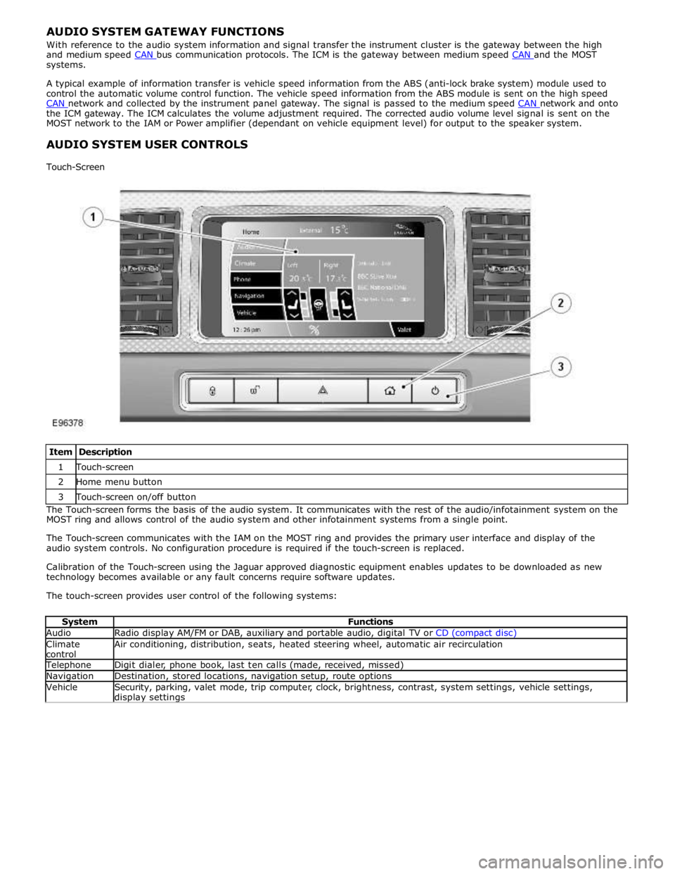
Touch-Screen
Item Description 1 Touch-screen 2 Home menu button 3 Touch-screen on/off button The Touch-screen forms the basis of the audio system. It communicates with the rest of the audio/infotainment system on the
MOST ring and allows control of the audio system and other infotainment systems from a single point.
The Touch-screen communicates with the IAM on the MOST ring and provides the primary user interface and display of the
audio system controls. No configuration procedure is required if the touch-screen is replaced.
Calibration of the Touch-screen using the Jaguar approved diagnostic equipment enables updates to be downloaded as new
technology becomes available or any fault concerns require software updates.
The touch-screen provides user control of the following systems:
System Functions Audio Radio display AM/FM or DAB, auxiliary and portable audio, digital TV or CD (compact disc) Climate
control Air conditioning, distribution, seats, heated steering wheel, automatic air recirculation Telephone Digit dialer, phone book, last ten calls (made, received, missed) Navigation Destination, stored locations, navigation setup, route options Vehicle
Security, parking, valet mode, trip computer, clock, brightness, contrast, system settings, vehicle settings, display settings
Page 1951 of 3039
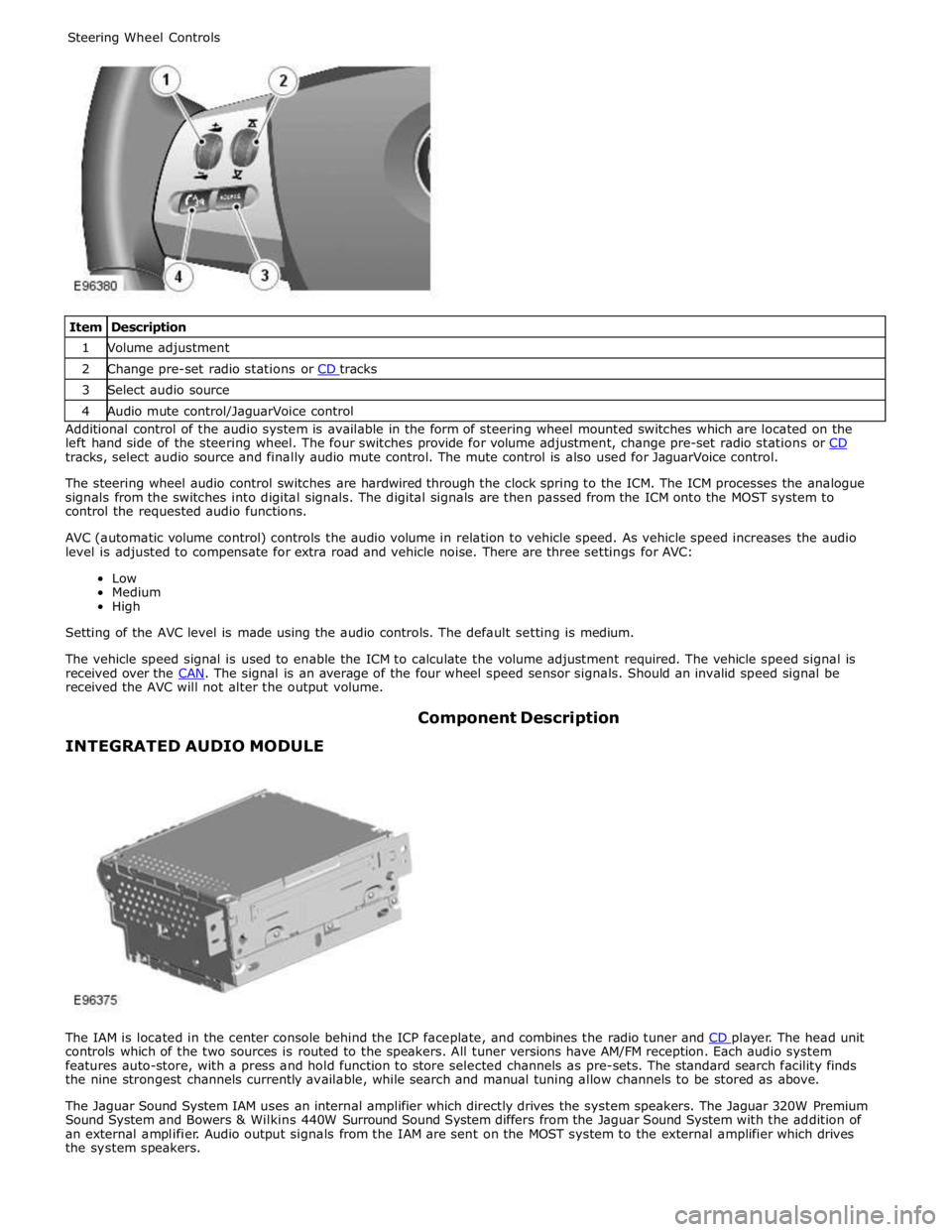
1 Volume adjustment 2 Change pre-set radio stations or CD tracks 3 Select audio source 4 Audio mute control/JaguarVoice control Additional control of the audio system is available in the form of steering wheel mounted switches which are located on the
left hand side of the steering wheel. The four switches provide for volume adjustment, change pre-set radio stations or CD tracks, select audio source and finally audio mute control. The mute control is also used for JaguarVoice control.
The steering wheel audio control switches are hardwired through the clock spring to the ICM. The ICM processes the analogue
signals from the switches into digital signals. The digital signals are then passed from the ICM onto the MOST system to
control the requested audio functions.
AVC (automatic volume control) controls the audio volume in relation to vehicle speed. As vehicle speed increases the audio
level is adjusted to compensate for extra road and vehicle noise. There are three settings for AVC:
Low
Medium
High
Setting of the AVC level is made using the audio controls. The default setting is medium.
The vehicle speed signal is used to enable the ICM to calculate the volume adjustment required. The vehicle speed signal is
received over the CAN. The signal is an average of the four wheel speed sensor signals. Should an invalid speed signal be received the AVC will not alter the output volume.
INTEGRATED AUDIO MODULE Component Description
The IAM is located in the center console behind the ICP faceplate, and combines the radio tuner and CD player. The head unit controls which of the two sources is routed to the speakers. All tuner versions have AM/FM reception. Each audio system
features auto-store, with a press and hold function to store selected channels as pre-sets. The standard search facility finds
the nine strongest channels currently available, while search and manual tuning allow channels to be stored as above.
The Jaguar Sound System IAM uses an internal amplifier which directly drives the system speakers. The Jaguar 320W Premium
Sound System and Bowers & Wilkins 440W Surround Sound System differs from the Jaguar Sound System with the addition of
an external amplifier. Audio output signals from the IAM are sent on the MOST system to the external amplifier which drives
the system speakers.
Page 1953 of 3039
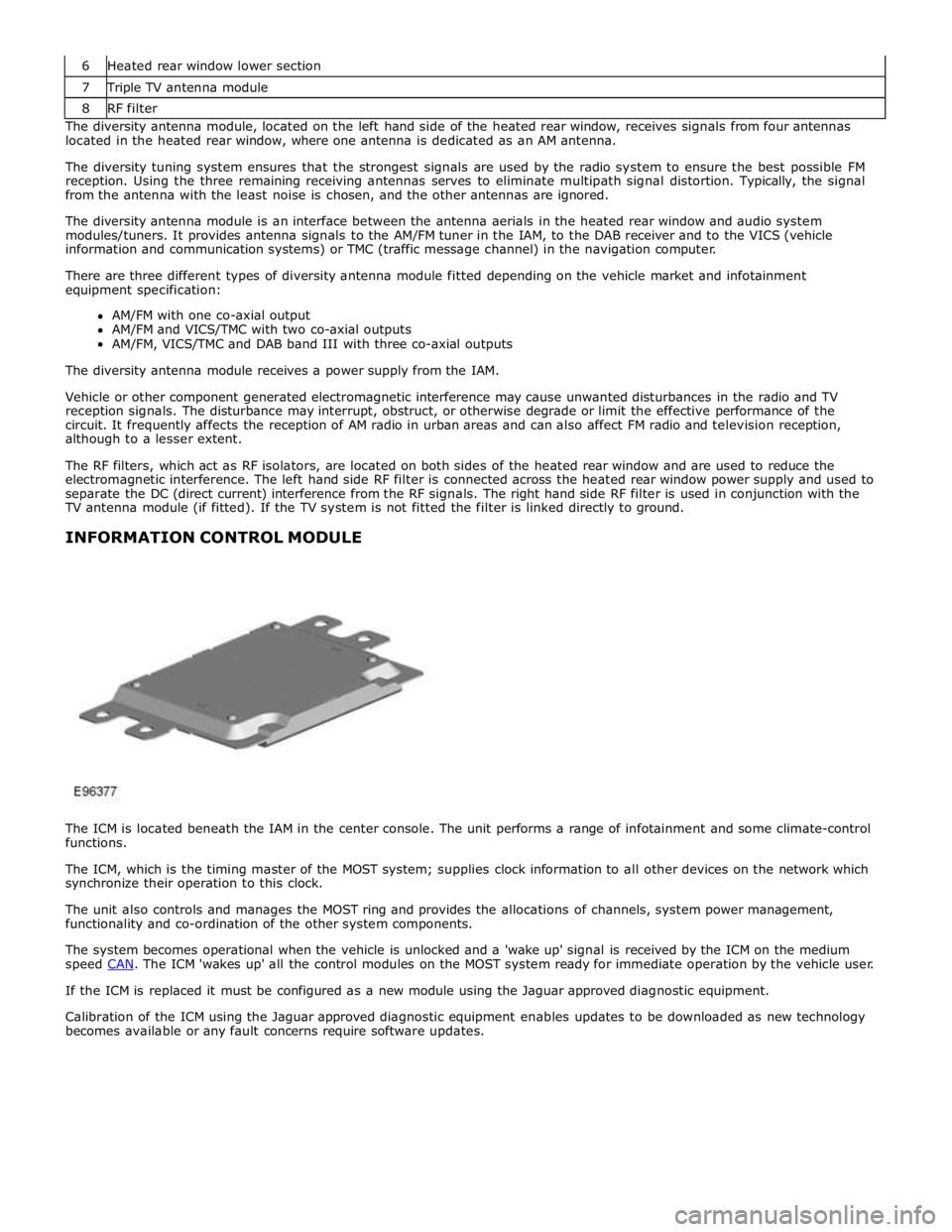
7 Triple TV antenna module 8 RF filter The diversity antenna module, located on the left hand side of the heated rear window, receives signals from four antennas
located in the heated rear window, where one antenna is dedicated as an AM antenna.
The diversity tuning system ensures that the strongest signals are used by the radio system to ensure the best possible FM
reception. Using the three remaining receiving antennas serves to eliminate multipath signal distortion. Typically, the signal
from the antenna with the least noise is chosen, and the other antennas are ignored.
The diversity antenna module is an interface between the antenna aerials in the heated rear window and audio system
modules/tuners. It provides antenna signals to the AM/FM tuner in the IAM, to the DAB receiver and to the VICS (vehicle
information and communication systems) or TMC (traffic message channel) in the navigation computer.
There are three different types of diversity antenna module fitted depending on the vehicle market and infotainment
equipment specification:
AM/FM with one co-axial output
AM/FM and VICS/TMC with two co-axial outputs
AM/FM, VICS/TMC and DAB band III with three co-axial outputs
The diversity antenna module receives a power supply from the IAM.
Vehicle or other component generated electromagnetic interference may cause unwanted disturbances in the radio and TV
reception signals. The disturbance may interrupt, obstruct, or otherwise degrade or limit the effective performance of the
circuit. It frequently affects the reception of AM radio in urban areas and can also affect FM radio and television reception,
although to a lesser extent.
The RF filters, which act as RF isolators, are located on both sides of the heated rear window and are used to reduce the
electromagnetic interference. The left hand side RF filter is connected across the heated rear window power supply and used to
separate the DC (direct current) interference from the RF signals. The right hand side RF filter is used in conjunction with the
TV antenna module (if fitted). If the TV system is not fitted the filter is linked directly to ground.
INFORMATION CONTROL MODULE
The ICM is located beneath the IAM in the center console. The unit performs a range of infotainment and some climate-control
functions.
The ICM, which is the timing master of the MOST system; supplies clock information to all other devices on the network which
synchronize their operation to this clock.
The unit also controls and manages the MOST ring and provides the allocations of channels, system power management,
functionality and co-ordination of the other system components.
The system becomes operational when the vehicle is unlocked and a 'wake up' signal is received by the ICM on the medium
speed CAN. The ICM 'wakes up' all the control modules on the MOST system ready for immediate operation by the vehicle user. If the ICM is replaced it must be configured as a new module using the Jaguar approved diagnostic equipment.
Calibration of the ICM using the Jaguar approved diagnostic equipment enables updates to be downloaded as new technology
becomes available or any fault concerns require software updates.
Page 1957 of 3039
NOTE: When the vehicle DAB radio is first used the system will not receive any digital stations until the auto-tune
function has been completed.
Digital radio channels are organized into groups called ensembles (also known as multiplexes). Some individual channels may
also provide a number of subchannels. For example, if several sports events are being held simultaneously, the channel may
temporarily choose to broadcast each different event on a separate subchannel.
DAB is broadcast across Europe, Canada and parts of Asia. System transmission is via a terrestrial network, on two separate
broadcasting bands:
DAB band-L
DAB band III
The DAB system requires additional components to be added to the audio system. DAB antennas and a receiver are fitted to
allow reception of the service.
Operation of the DAB system is the same as the radio operation with selections made through the touch-screen and ICP to
access and navigate the system functions.
The DAB receiver is a dedicated tuner which is controlled by the ICM on the MOST ring. The receiver processes the signals from
the DAB antennas. Information is transmitted on the MOST ring and processed by the ICM. The processed information is sent
out to the power amplifier or IAM (with internal amplifier) and broadcast through the speaker system.
No configuration procedure is required if the DAB receiver is replaced. Calibration of the DAB receiver using the Jaguar
approved diagnostic equipment enables updates to be downloaded as new technology becomes available or any fault concerns
require software updates.
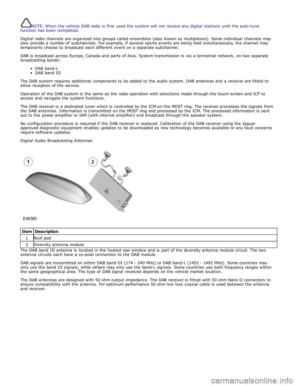
Digital Audio Broadcasting Antennas
Item Description 1 Roof pod 2 Diversity antenna module The DAB band III antenna is located in the heated rear window and is part of the diversity antenna module circuit. The two
antenna circuits each have a co-axial connection to the DAB module.
DAB signals are transmitted on either DAB band III (174 - 240 MHz) or DAB band-L (1452 - 1492 MHz). Some countries may
only use the band III signals, while others may only use the band-L signals. Some countries use both frequency ranges within
the same geographical area. The type of DAB signal received depends on the vehicle market location.
The DAB antennas are designed with 50 ohm output impedance. The DAB receiver is fitted with 50 ohm fakra II connectors to
ensure compatibility with the antenna. For optimum performance 50 ohm low loss coaxial cable is used between the antenna
and receiver.
Page 1980 of 3039
the roof pod and is shared with the DAB (digital audio broadcasting) band L antenna or satellite radio antenna where fitted.
The roof pod is located externally in a central position towards the rear of the roof.
The GPS antenna is designed with 50 ohm output impedance. The navigation computer is fitted with 50 ohm fakra II connectors to ensure compatibility with the antenna. For optimum performance 50 ohm low loss coaxial cable is used between
the antenna and navigation computer.
It is possible for the GPS antenna to lose the signal from the GPS satellites; In hilly or tree lined areas
Built up areas with tall buildings
In multi storey car parks
In garages
In tunnels
On bridges
During heavy rain or thunderstorms
When the signal is lost the navigation computer will continue to give guidance using memory mapped data from the DVD map until the signal is restored.
TMC/VICS FM Antenna
Data messages for both TMC (traffic message channel) and VICS (vehicle information and communication system) are received
through the FM antennas and diversity antenna module located in the heated rear window.
VICS Beacon Antenna (Japan Only)
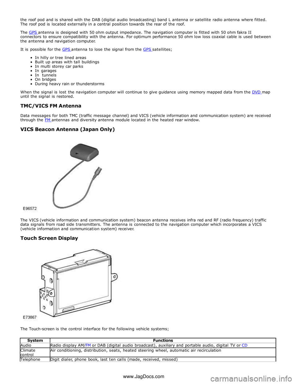
The VICS (vehicle information and communication system) beacon antenna receives infra red and RF (radio frequency) traffic
data signals from road side transmitters. The antenna is connected to the navigation computer which incorporates a VICS
(vehicle information and communication system) receiver.
Touch Screen Display
The Touch-screen is the control interface for the following vehicle systems;
System Functions Audio Radio display AM/FM or DAB (digital audio broadcast), auxiliary and portable audio, digital TV or CD Climate
control Air conditioning, distribution, seats, heated steering wheel, automatic air recirculation Telephone Digit dialer, phone book, last ten calls (made, received, missed) www.JagDocs.com