Page 1079 of 3039
3. NOTE: Tighten the bolts in the indicated sequence.
Torque:
M6 12 Nm M8 20 Nm
4. Torque: 12 Nm
5. Refer to: Brake Vacuum Pump - V8 5.0L Petrol/V8 S/C 5.0L Petrol (206-07 Power Brake Actuation, Removal and Installation).
6. Torque: 25 Nm
Page 1080 of 3039

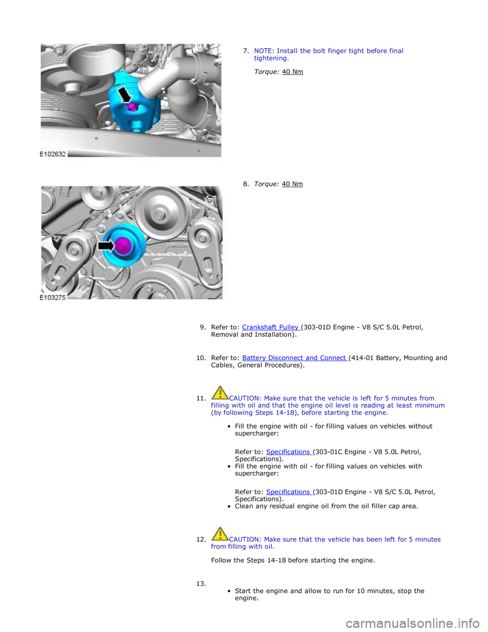
7. NOTE: Install the bolt finger tight before final
tightening.
Torque: 40 Nm
8. Torque: 40 Nm
9. Refer to: Crankshaft Pulley (303-01D Engine - V8 S/C 5.0L Petrol, Removal and Installation).
10. Refer to: Battery Disconnect and Connect (414-01 Battery, Mounting and Cables, General Procedures).
11. CAUTION: Make sure that the vehicle is left for 5 minutes from
filling with oil and that the engine oil level is reading at least minimum
(by following Steps 14-18), before starting the engine.
Fill the engine with oil - for filling values on vehicles without
supercharger:
Refer to: Specifications (303-01C Engine - V8 5.0L Petrol, Specifications).
Fill the engine with oil - for filling values on vehicles with
supercharger:
Refer to: Specifications (303-01D Engine - V8 S/C 5.0L Petrol, Specifications).
Clean any residual engine oil from the oil filler cap area.
12. CAUTION: Make sure that the vehicle has been left for 5 minutes
from filling with oil.
Follow the Steps 14-18 before starting the engine.
13.
Start the engine and allow to run for 10 minutes, stop the
engine.
Page 1087 of 3039

Engine - V8 S/C 5.0L Petrol - Engine
Removal Published: 19-Nov-2013
NOTES:
Some variation in the illustrations may occur, but the essential information is always correct.
If a new engine is to be installed, remove the intake manifold to access the top transmission retaining bolts.
1. Refer to: Battery Disconnect and Connect (414-01 Battery, Mounting and Cables, General Procedures).
2. WARNING: Make sure to support the vehicle with axle stands.
Raise and support the vehicle.
3. Refer to: Cowl Vent Screen (501-02 Front End Body Panels, Removal and Installation).
4. Refer to: Air Cleaner LH (303-12C Intake Air Distribution and Filtering - V8 5.0L Petrol, Removal and Installation).
5. Refer to: Air Cleaner RH (303-12C Intake Air Distribution and Filtering - V8 5.0L Petrol, Removal and Installation).
6. Refer to: Cooling System Partial Draining, Filling and Bleeding - V8 S/C 5.0L Petrol (303-03C Engine Cooling - V8 5.0L Petrol/V8 S/C 5.0L Petrol, General Procedures).
7. Refer to: Air Conditioning (A/C) System Recovery, Evacuation and Charging (412-00 Climate Control System - General Information, General Procedures).
8. Refer to: Hood (501-02 Front End Body Panels, Removal and Installation).
9. Refer to: Cooling Fan Motor and Shroud - Vehicles With: Supercharger (303-03C Engine Cooling - V8 5.0L Petrol/V8 S/C 5.0L Petrol, Removal
and Installation).
10. Refer to: Transmission - V8 5.0L Petrol/V8 S/C 5.0L Petrol (307-01B Automatic Transmission/Transaxle - TDV6 3.0L Diesel /V8 5.0L Petrol/V8
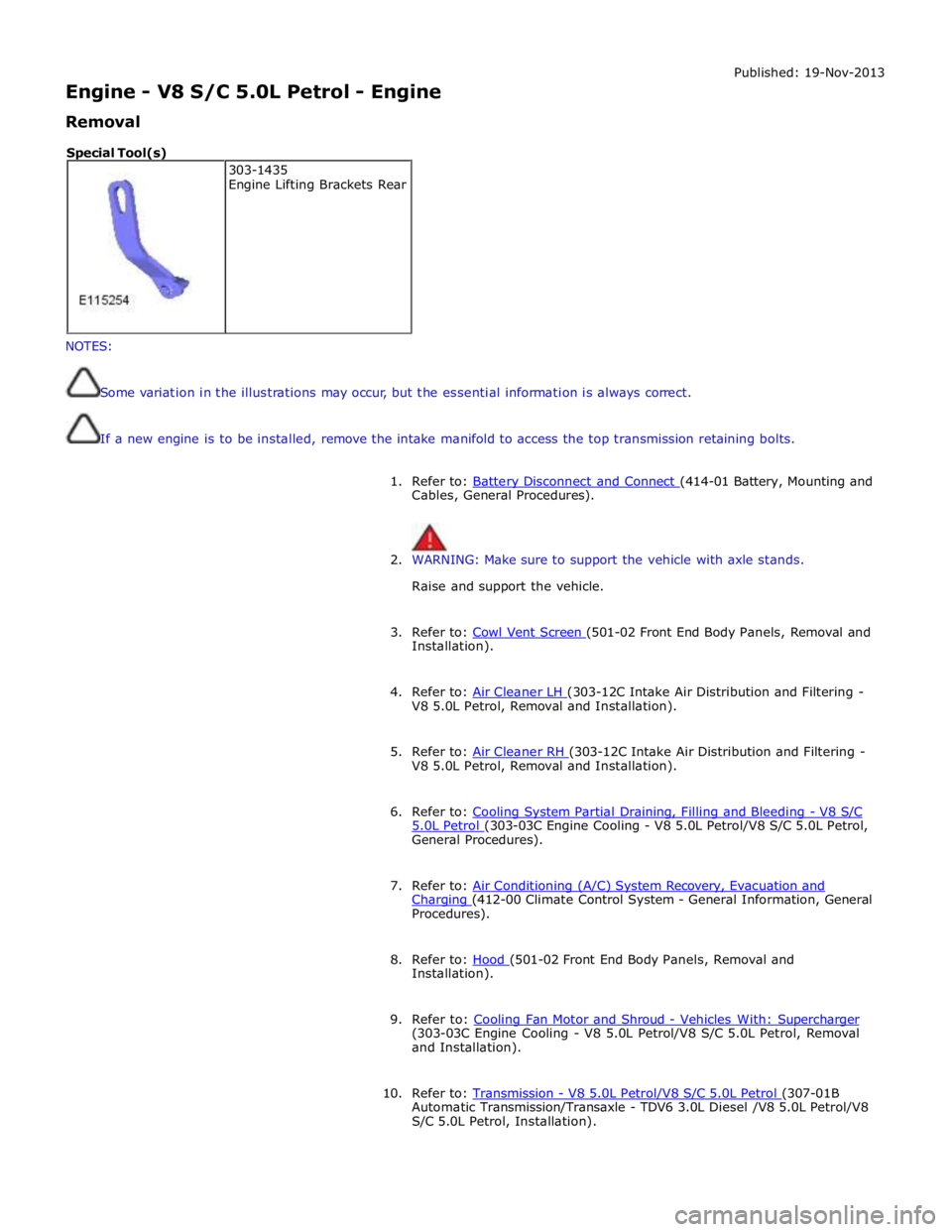
S/C 5.0L Petrol, Installation). 303-1435
Engine Lifting Brackets Rear Special Tool(s)
Page 1097 of 3039
Engine - V8 S/C 5.0L Petrol - Engine
Installation
NOTES:
Some variation in the illustrations may occur, but the essential information is always correct. Published: 19-Nov-2013
If a new engine is to be installed, remove the intake manifold to access the top transmission retaining bolts.
1. NOTE: This step requires the aid of another technician.
Install the engine assembly.
2. Torque: 45 Nm
Page 1107 of 3039
Jaguar Premium Cooling System Fluid WSS-M97B44-D Jaguar Premium Cooling System Flush EGR-M14P7-A
Engine Capacity 5.0L with supercharger 12.32L 5.0L without supercharger 12.5L
Description Nm lb-ft lb-in Coolant expansion tank retaining bolt 7 - 62 Cooling fan motor and shroud retaining nuts 7 - 62 Thermostat housing retaining bolts 10 7 - Coolant pump retaining bolts 11 8 - Radiator retaining bolts 9 - 80 Radiator drain plug 2 - 18 Coolant bleed screw(s) 3 - 27
Page 1177 of 3039

Fuel Charging and Controls - V8 S/C 5.0L Petrol -
WARNINGS: Published: 11-May-2011
Do not smoke or carry lighted tobacco or open flame of any type when working on or near any fuel related components.
Highly flammable vapors are always present and may ignite. Failure to follow these instructions may result in personal injury.
Before any work is carried out on the fuel system, ground the vehicle to earth and maintain the ground connection until
the work is complete.
CAUTION: Before disconnecting or removing components, make sure the area around the joint faces and connections are
clean. Plug open connections to prevent contamination.
NOTE: Tighten the fuel rail high pressure fuel pump fuel line unions and fuel rail crossover pipe unions as it is instructed
in service manual.
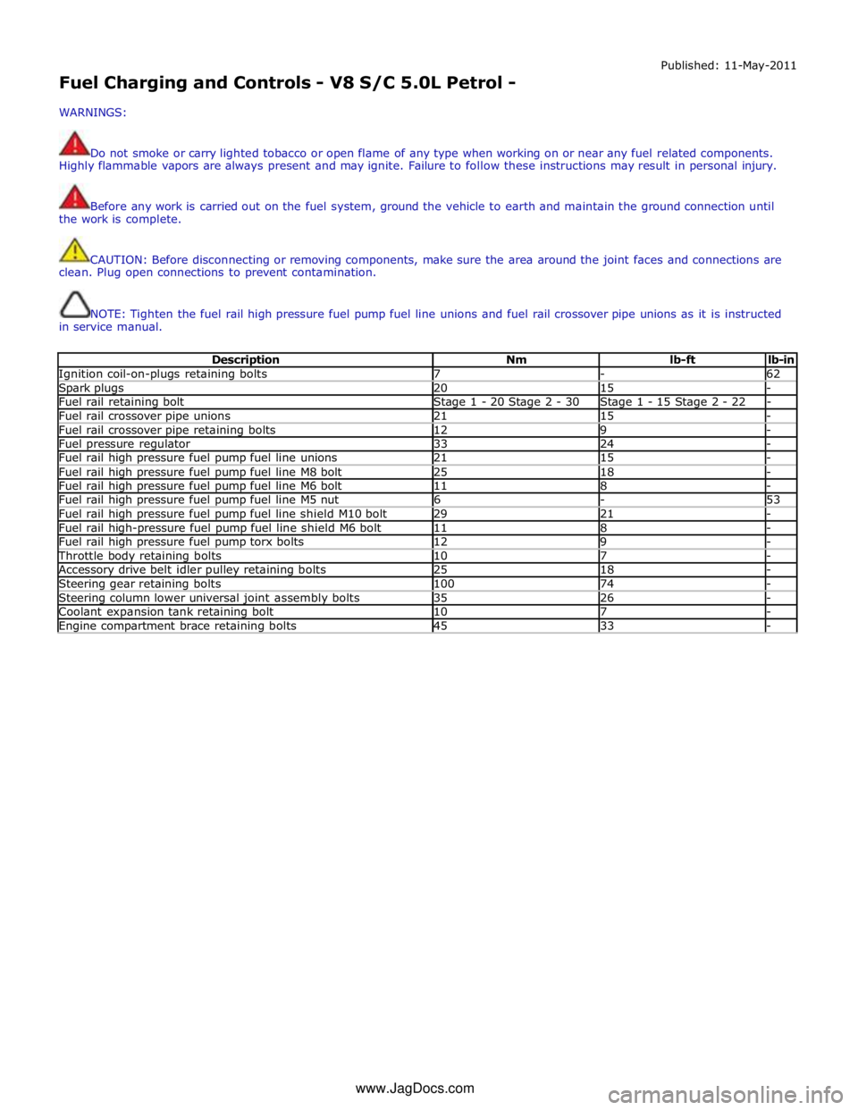
Description Nm lb-ft lb-in Ignition coil-on-plugs retaining bolts 7 - 62 Spark plugs 20 15 - Fuel rail retaining bolt Stage 1 - 20 Stage 2 - 30 Stage 1 - 15 Stage 2 - 22 - Fuel rail crossover pipe unions 21 15 - Fuel rail crossover pipe retaining bolts 12 9 - Fuel pressure regulator 33 24 - Fuel rail high pressure fuel pump fuel line unions 21 15 - Fuel rail high pressure fuel pump fuel line M8 bolt 25 18 - Fuel rail high pressure fuel pump fuel line M6 bolt 11 8 - Fuel rail high pressure fuel pump fuel line M5 nut 6 - 53 Fuel rail high pressure fuel pump fuel line shield M10 bolt 29 21 - Fuel rail high-pressure fuel pump fuel line shield M6 bolt 11 8 - Fuel rail high pressure fuel pump torx bolts 12 9 - Throttle body retaining bolts 10 7 - Accessory drive belt idler pulley retaining bolts 25 18 - Steering gear retaining bolts 100 74 - Steering column lower universal joint assembly bolts 35 26 - Coolant expansion tank retaining bolt 10 7 - Engine compartment brace retaining bolts 45 33 - www.JagDocs.com
Page 1184 of 3039
1 LH fuel rail 2 Crossover tube 3 RH fuel rail 4 FRP sensor 5 Fuel injector (8 off) The fuel rails and crossover tube are made from stainless steel. Bolts attach each fuel rail to the related cylinder head. The
crossover tube connects the front high pressure line to the LH fuel rail, which ensures there is equal pressure in the two fuel rails. Four P-clips attach the crossover tube to the intercooler-tank top.
The rear of the RH fuel rail incorporates a threaded boss for installation of the FRP sensor. FUEL RAILS AND CROSSOVER TUBE
Page 1198 of 3039
6. CAUTIONS:
Make sure that the area around the open fuel injector ports are clean
and free of foreign material and lubricant prior to installing the fuel injector.
When Installing the fuel injector(s), make sure that the Teflon seal is
clean and free of foreign material and lubricant.
7. CAUTIONS:
If new fuel injectors are installed, a new injector clamp must be
installed
Make sure that the fuel injector is aligned and installed into the fuel
rail correctly, as noted in the removal step.
Tighten the fuel rail retaining bolts a turn at a time until the correct
torque is achieved.
NOTE: Lubricate the fuel injector O-ring seals with clean engine oil.
Torque: 20 Nm
8. Special Tool(s): 310-200-01, 310-200-02 9. Torque: 20 Nm