Page 790 of 3039
Steering Column - Steering Column Flexible Coupling
Removal and Installation
Removal
NOTE: Removal steps in this procedure may contain installation details. Published: 11-May-2011
1. Refer to: Battery Disconnect and Connect (414-01 Battery, Mounting and Cables, General Procedures).
2. WARNING: Make sure to support the vehicle with axle stands.
Raise and support the vehicle.
3. Refer to: Air Deflector (501-02 Front End Body Panels, Removal and Installation).
4. Refer to: Instrument Panel Lower Trim Panel (501-12 Instrument Panel and Console, Removal and Installation).
5. WARNING: Make sure that a new steering column
flexible coupling bolt is installed.
Torque: 30 Nm
6. Torque: 10 Nm
Page 792 of 3039

Steering Column - Steering Wheel
Removal and Installation Published: 24-Mar-2014
Removal
1. Make the SRS system safe.
For additional information, refer to: Standard Workshop Practices (100-00 General Information, Description and Operation).
2. Disconnect the battery ground cable.
For additional information, refer to: Battery Disconnect and Connect (414-01 Battery, Mounting and Cables, General Procedures).
3. Remove the driver air bag module.
For additional information, refer to: Driver Air Bag Module (501-20B Supplemental Restraint System, Removal and Installation).
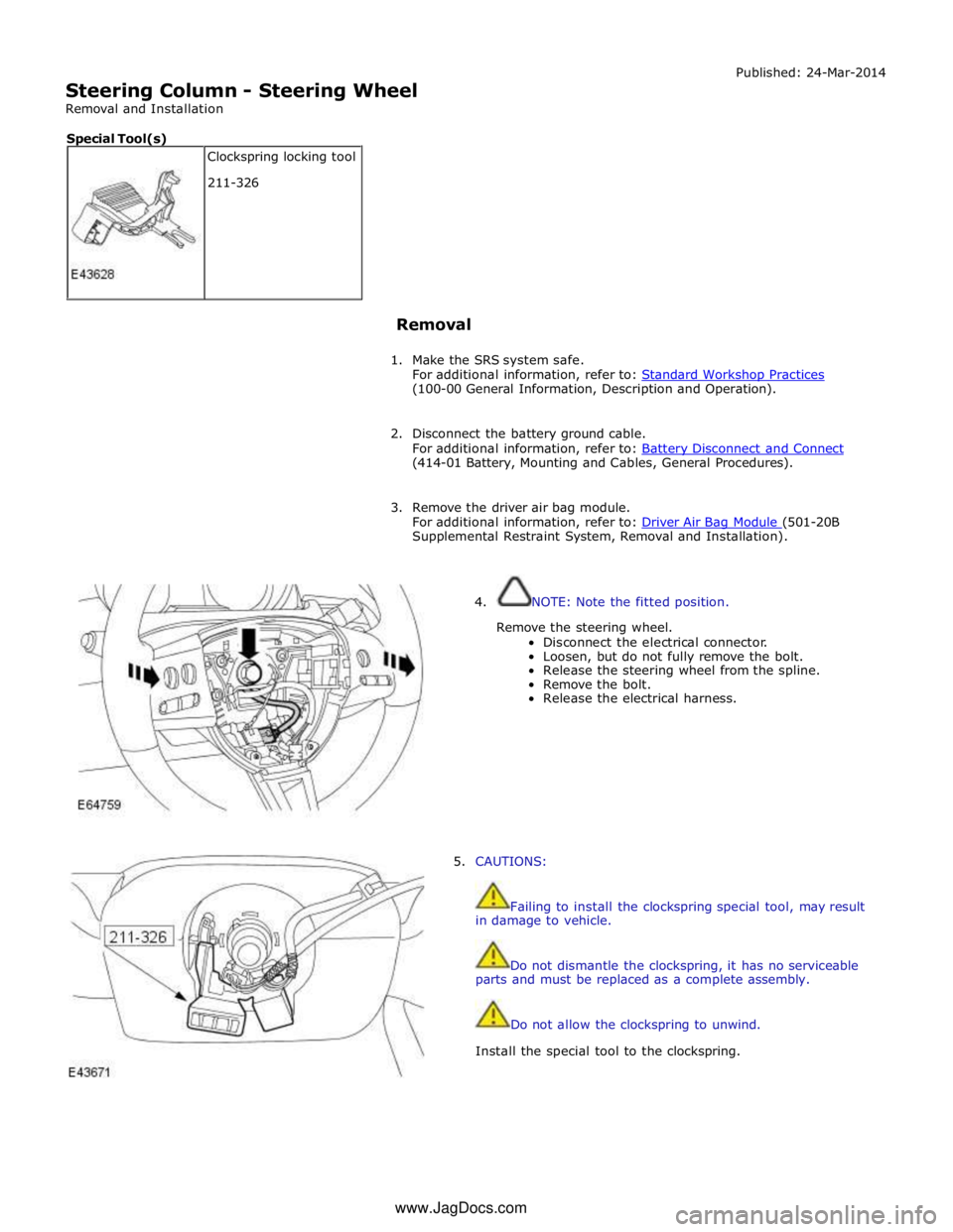
4. NOTE: Note the fitted position.
Remove the steering wheel.
Disconnect the electrical connector.
Loosen, but do not fully remove the bolt.
Release the steering wheel from the spline.
Remove the bolt.
Release the electrical harness.
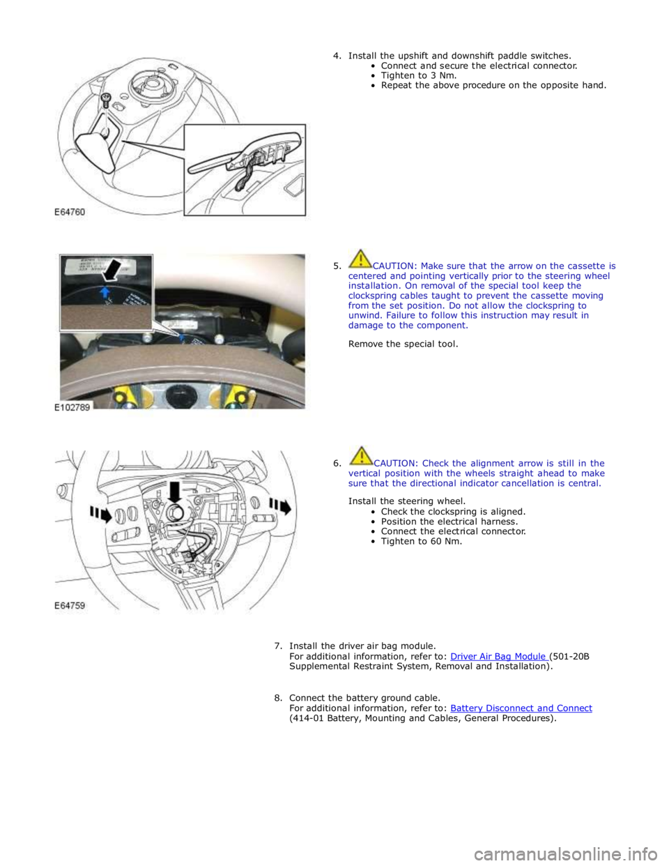
5. CAUTIONS:
Failing to install the clockspring special tool, may result
in damage to vehicle.
Do not dismantle the clockspring, it has no serviceable
parts and must be replaced as a complete assembly.
Do not allow the clockspring to unwind.
Install the special tool to the clockspring. Clockspring locking tool
211-326 Special Tool(s) www.JagDocs.com
Page 793 of 3039
6. NOTE: Do not disassemble further if the component is
removed for access only.
Remove the upshift and downshift paddle switches.
Remove the Torx bolt.
Release the assembly.
Disconnect the electrical connector.
Repeat the procedure and remove the opposite
hand.
7. NOTE: The steering wheel is shown removed for
clarity.
Release the steering wheel switch assembly.
Remove the Torx bolt.
Repeat the procedure and remove the opposite
hand.
8. Remove the air bag housing.
Remove the 4 Torx bolts.
Release the electrical harness.
9. Remove the air bag ground cable.
Remove the Torx screw.
Page 794 of 3039
Installation
1. Install the air bag ground cable.
Install the Torx screw.
2. Install the air bag housing.
Secure the electrical harness.
Tighten to 6 Nm.
3. Secure the steering wheel switch assembly.
Connect and secure the electrical connectors.
Tighten to 3 Nm.
Repeat the above procedure on the opposite hand.
Page 795 of 3039

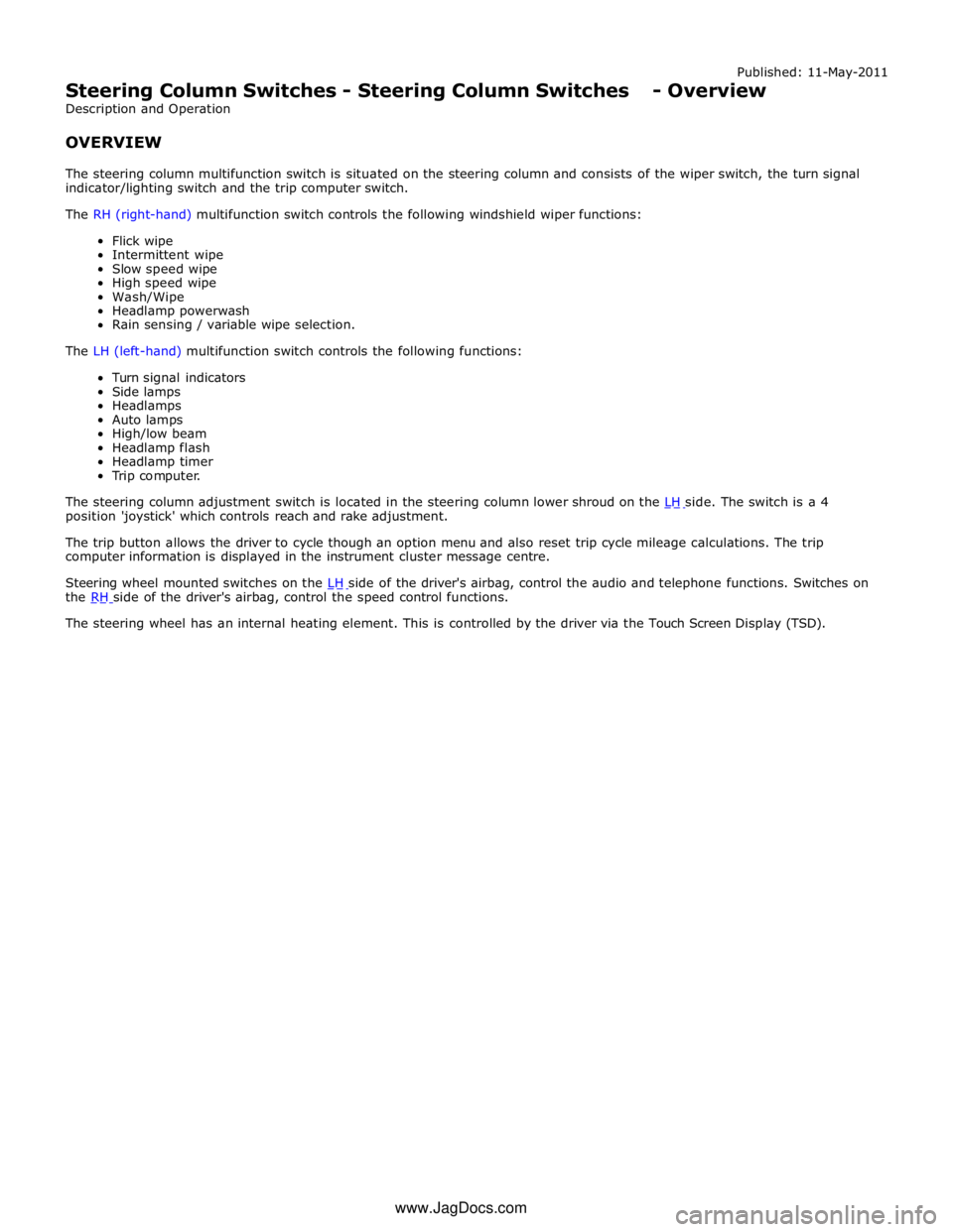
4. Install the upshift and downshift paddle switches.
Connect and secure the electrical connector.
Tighten to 3 Nm.
Repeat the above procedure on the opposite hand.
5. CAUTION: Make sure that the arrow on the cassette is
centered and pointing vertically prior to the steering wheel
installation. On removal of the special tool keep the
clockspring cables taught to prevent the cassette moving
from the set position. Do not allow the clockspring to
unwind. Failure to follow this instruction may result in
damage to the component.
Remove the special tool.
6. CAUTION: Check the alignment arrow is still in the
vertical position with the wheels straight ahead to make
sure that the directional indicator cancellation is central.
Install the steering wheel.
Check the clockspring is aligned.
Position the electrical harness.
Connect the electrical connector.
Tighten to 60 Nm.
7. Install the driver air bag module.
For additional information, refer to: Driver Air Bag Module (501-20B Supplemental Restraint System, Removal and Installation).
8. Connect the battery ground cable.
For additional information, refer to: Battery Disconnect and Connect (414-01 Battery, Mounting and Cables, General Procedures).
Page 796 of 3039
1 Audio and telephone switches 2 Steering column adjustment switch 3 LH (left-hand) (-) gear change paddle switch 4 Steering column multifunction switches and clockspring 5 RH (right-hand) (+) gear change paddle switch 6 Speed control switches (Adaptive Speed Control switch pack shown, non adaptive speed control switch pack similar)
Page 797 of 3039

Published: 11-May-2011
Steering Column Switches - Steering Column Switches - Overview
Description and Operation
OVERVIEW
The steering column multifunction switch is situated on the steering column and consists of the wiper switch, the turn signal
indicator/lighting switch and the trip computer switch.
The RH (right-hand) multifunction switch controls the following windshield wiper functions:
Flick wipe
Intermittent wipe
Slow speed wipe
High speed wipe
Wash/Wipe
Headlamp powerwash
Rain sensing / variable wipe selection.
The LH (left-hand) multifunction switch controls the following functions:
Turn signal indicators
Side lamps
Headlamps
Auto lamps
High/low beam
Headlamp flash
Headlamp timer
Trip computer.
The steering column adjustment switch is located in the steering column lower shroud on the LH side. The switch is a 4 position 'joystick' which controls reach and rake adjustment.
The trip button allows the driver to cycle though an option menu and also reset trip cycle mileage calculations. The trip
computer information is displayed in the instrument cluster message centre.
Steering wheel mounted switches on the LH side of the driver's airbag, control the audio and telephone functions. Switches on the RH side of the driver's airbag, control the speed control functions. The steering wheel has an internal heating element. This is controlled by the driver via the Touch Screen Display (TSD). www.JagDocs.com
Page 798 of 3039
Published: 11-May-2011
Steering Column Switches - Steering Column Switches - System Operation
and Component Description
Description and Operation
Control Diagram
NOTE: A = Hardwired; N = Medium speed CAN bus; P = Fibre Optic MOST ring
Item Description 1 Battery 2 BJB (battery junction box) 3 CJB (central junction box) 4 Heated steering wheel slip rings 5 Heated steering wheel control module 6 Steering wheel heater element