2010 JAGUAR XFR Engine
[x] Cancel search: EnginePage 739 of 3039

Lower steering column slider pinch bolt 35 26 - Lower steering column to steering gear pinch bolt 35 26 - Power steering control valve actuator 2 - 18 Power steering fluid cooler retaining bolts 7 - 62 Power steering pump pulley retaining bolts 20 25 - Power steering pump retaining bolts - All except vehicles with diesel engine 25 18 - Power steering pump retaining bolts - Vehicles with diesel engine 22 16 - Power steering pump to steering gear pressure line 25 18 - Steering gear retaining bolts 100 74 - Steering gear supply and return lines 10 - 89 www.JagDocs.com
Page 741 of 3039

compartment, forward of the front suspension housing.
On petrol engine vehicles, a fluid cooler is located in front of the engine cooling radiator. Diesel models do not have a fluid
cooler.
Servotronic 2 adds electronic control and speed sensitive steering to the steering gear. The Servotronic 2 feature provides easy
and comfortable steering operation when parking, improved 'road feel' at increased road speeds and adds an integrated,
positive center feel feature which optimises steering wheel torque during high speed driving. The Servotronic 2 system is
controlled by software which is incorporated into the instrument cluster. The software responds to road speed signals and
controls the power assistance via a transducer valve located on the steering gear valve housing.
Page 743 of 3039

Torsion bar 19 Power steering fluid reservoir 20 Valve rotor 21 Reaction piston 22 Reaction chamber 23 Centering piece 24 Pressure relief/flow limiting valve 25 Power steering pump 26 Inner tie-rod 27 Pinion 28 Valve sleeve 29 Steering gear rack 30 Steering gear housing 31 Power assist cylinder - right 32 Piston 33 Power assist cylinder - left When the engine is started, the power steering pump draws fluid from the reservoir down the low pressure suction line. The
fluid passes through the pump and is delivered at pressure, via a hose, to the steering rack valve unit.
The pressurized fluid flows through a connecting bore in the valve and, via the feed fluid radial groove and the transverse
bores in the valve sleeve, passes to the feed fluid control groove of the valve rotor.
In the neutral (straight ahead) position , the fluid passes over the open feed fluid control edges to all valve sleeve axial
grooves. The fluid then passes through return fluid control edges and the return fluid grooves of the valve rotor, back to the
reservoir passes via the fluid cooler.
Simultaneously, the radial grooves of the valve and their associated pipes provide a connection the left and right power assist
cylinders.
Power Steering in Right Turn Position
Page 745 of 3039
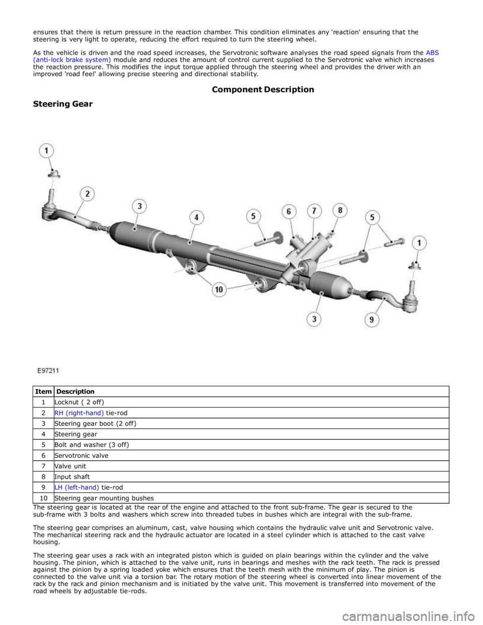
1 Locknut ( 2 off) 2 RH (right-hand) tie-rod 3 Steering gear boot (2 off) 4 Steering gear 5 Bolt and washer (3 off) 6 Servotronic valve 7 Valve unit 8 Input shaft 9 LH (left-hand) tie-rod 10 Steering gear mounting bushes The steering gear is located at the rear of the engine and attached to the front sub-frame. The gear is secured to the
sub-frame with 3 bolts and washers which screw into threaded tubes in bushes which are integral with the sub-frame.
The steering gear comprises an aluminum, cast, valve housing which contains the hydraulic valve unit and Servotronic valve.
The mechanical steering rack and the hydraulic actuator are located in a steel cylinder which is attached to the cast valve
housing.
The steering gear uses a rack with an integrated piston which is guided on plain bearings within the cylinder and the valve
housing. The pinion, which is attached to the valve unit, runs in bearings and meshes with the rack teeth. The rack is pressed
against the pinion by a spring loaded yoke which ensures that the teeth mesh with the minimum of play. The pinion is
connected to the valve unit via a torsion bar. The rotary motion of the steering wheel is converted into linear movement of the
rack by the rack and pinion mechanism and is initiated by the valve unit. This movement is transferred into movement of the
road wheels by adjustable tie-rods.
Page 749 of 3039
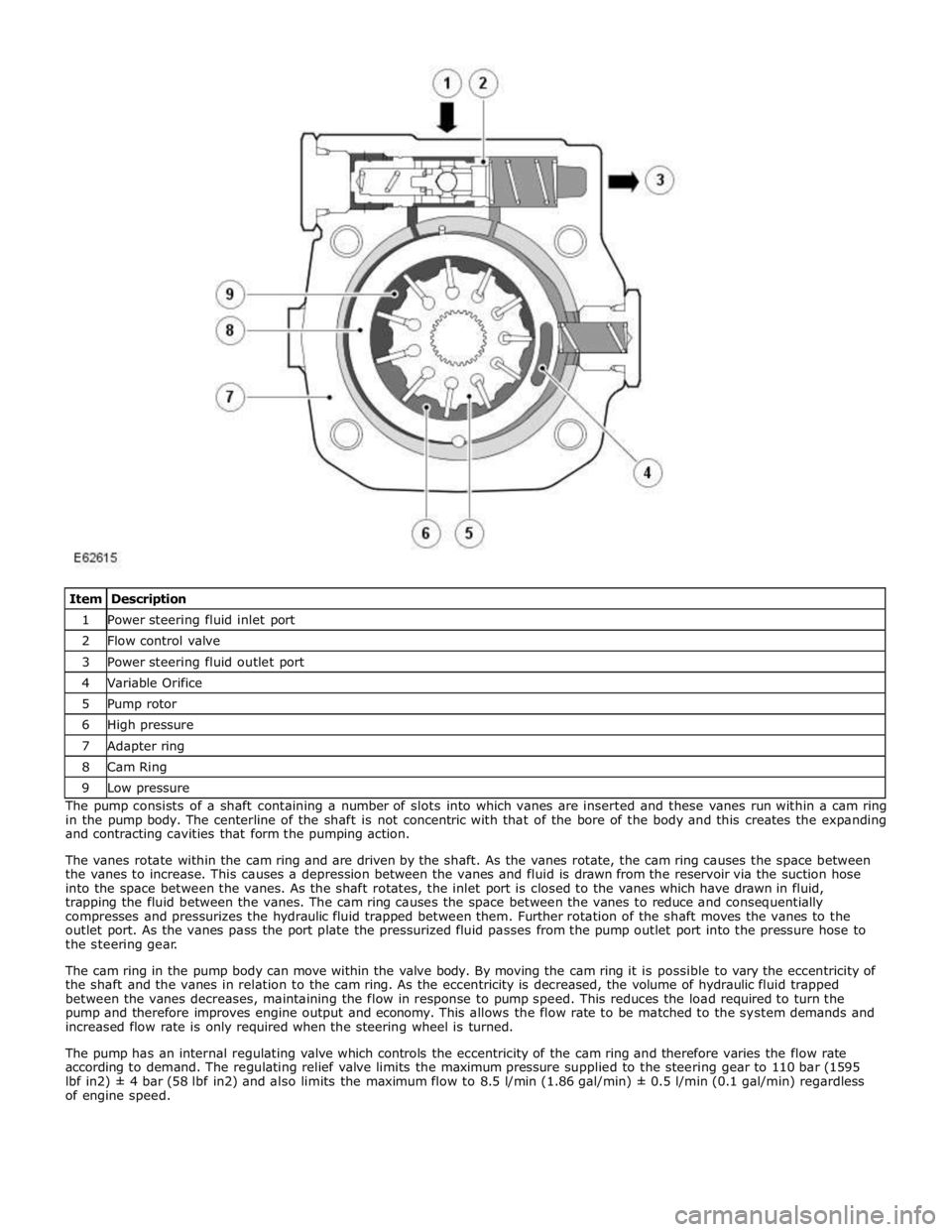
1 Power steering fluid inlet port 2 Flow control valve 3 Power steering fluid outlet port 4 Variable Orifice 5 Pump rotor 6 High pressure 7 Adapter ring 8 Cam Ring 9 Low pressure The pump consists of a shaft containing a number of slots into which vanes are inserted and these vanes run within a cam ring
in the pump body. The centerline of the shaft is not concentric with that of the bore of the body and this creates the expanding
and contracting cavities that form the pumping action.
The vanes rotate within the cam ring and are driven by the shaft. As the vanes rotate, the cam ring causes the space between
the vanes to increase. This causes a depression between the vanes and fluid is drawn from the reservoir via the suction hose
into the space between the vanes. As the shaft rotates, the inlet port is closed to the vanes which have drawn in fluid,
trapping the fluid between the vanes. The cam ring causes the space between the vanes to reduce and consequentially
compresses and pressurizes the hydraulic fluid trapped between them. Further rotation of the shaft moves the vanes to the
outlet port. As the vanes pass the port plate the pressurized fluid passes from the pump outlet port into the pressure hose to
the steering gear.
The cam ring in the pump body can move within the valve body. By moving the cam ring it is possible to vary the eccentricity of
the shaft and the vanes in relation to the cam ring. As the eccentricity is decreased, the volume of hydraulic fluid trapped
between the vanes decreases, maintaining the flow in response to pump speed. This reduces the load required to turn the
pump and therefore improves engine output and economy. This allows the flow rate to be matched to the system demands and
increased flow rate is only required when the steering wheel is turned.
The pump has an internal regulating valve which controls the eccentricity of the cam ring and therefore varies the flow rate
according to demand. The regulating relief valve limits the maximum pressure supplied to the steering gear to 110 bar (1595
lbf in2) ± 4 bar (58 lbf in2) and also limits the maximum flow to 8.5 l/min (1.86 gal/min) ± 0.5 l/min (0.1 gal/min) regardless
of engine speed.
Page 750 of 3039
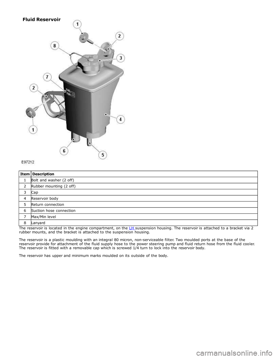
1 Bolt and washer (2 off) 2 Rubber mounting (2 off) 3 Cap 4 Reservoir body 5 Return connection 6 Suction hose connection 7 Max/Min level 8 Lanyard The reservoir is located in the engine compartment, on the LH suspension housing. The reservoir is attached to a bracket via 2 rubber mounts, and the bracket is attached to the suspension housing.
The reservoir is a plastic moulding with an integral 80 micron, non-serviceable filter. Two moulded ports at the base of the
reservoir provide for attachment of the fluid supply hose to the power steering pump and fluid return hose from the fluid cooler.
The reservoir is fitted with a removable cap which is screwed 1/4 turn to lock into the reservoir body.
The reservoir has upper and minimum marks moulded on its outside of the body. Fluid Reservoir
Page 811 of 3039
Engine System - General Information - Engine 5.0L
Diagnosis and Testing
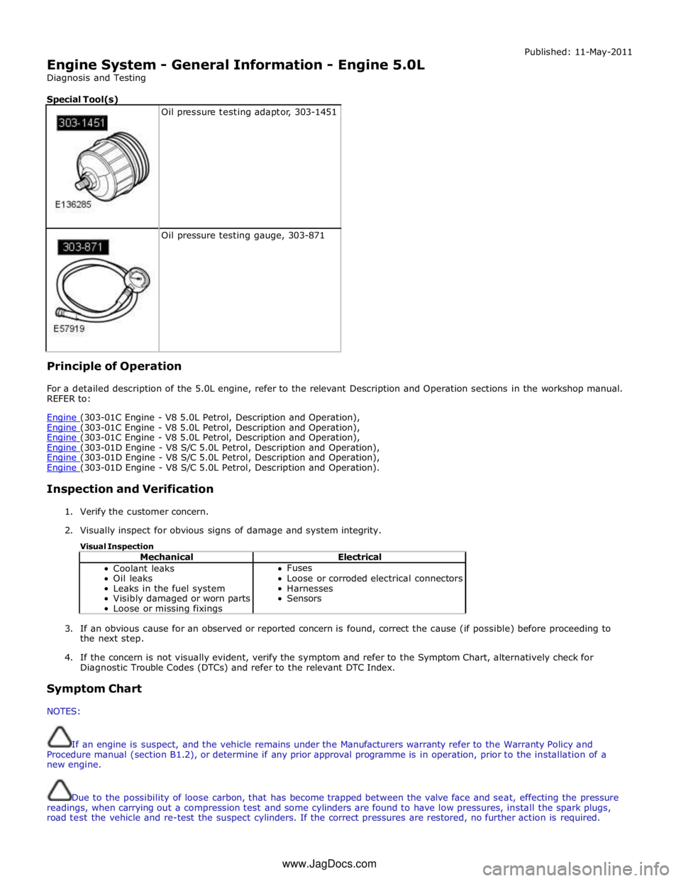
Special Tool(s)
Oil pressure testing adaptor, 303-1451
Oil pressure testing gauge, 303-871 Principle of Operation Published: 11-May-2011
For a detailed description of the 5.0L engine, refer to the relevant Description and Operation sections in the workshop manual.
REFER to:
Engine (303-01C Engine - V8 5.0L Petrol, Description and Operation), Engine (303-01C Engine - V8 5.0L Petrol, Description and Operation), Engine (303-01C Engine - V8 5.0L Petrol, Description and Operation), Engine (303-01D Engine - V8 S/C 5.0L Petrol, Description and Operation), Engine (303-01D Engine - V8 S/C 5.0L Petrol, Description and Operation), Engine (303-01D Engine - V8 S/C 5.0L Petrol, Description and Operation).
Inspection and Verification
1. Verify the customer concern.
2. Visually inspect for obvious signs of damage and system integrity.
Visual Inspection
Mechanical Electrical Coolant leaks
Oil leaks
Leaks in the fuel system
Visibly damaged or worn parts
Loose or missing fixings Fuses
Loose or corroded electrical connectors
Harnesses
Sensors
3. If an obvious cause for an observed or reported concern is found, correct the cause (if possible) before proceeding to
the next step.
4. If the concern is not visually evident, verify the symptom and refer to the Symptom Chart, alternatively check for
Diagnostic Trouble Codes (DTCs) and refer to the relevant DTC Index.
Symptom Chart
NOTES:
If an engine is suspect, and the vehicle remains under the Manufacturers warranty refer to the Warranty Policy and
Procedure manual (section B1.2), or determine if any prior approval programme is in operation, prior to the installation of a
new engine.
Due to the possibility of loose carbon, that has become trapped between the valve face and seat, effecting the pressure
readings, when carrying out a compression test and some cylinders are found to have low pressures, install the spark plugs,
road test the vehicle and re-test the suspect cylinders. If the correct pressures are restored, no further action is required. www.JagDocs.com
Page 812 of 3039
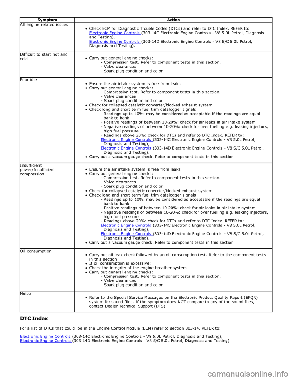
Symptom Action All engine related issues
Check ECM for Diagnostic Trouble Codes (DTCs) and refer to DTC Index. REFER to:
Electronic Engine Controls (303-14C Electronic Engine Controls - V8 5.0L Petrol, Diagnosis and Testing),
Electronic Engine Controls (303-14D Electronic Engine Controls - V8 S/C 5.0L Petrol, Diagnosis and Testing). Difficult to start hot and
cold
Carry out general engine checks:
- Compression test. Refer to component tests in this section.
- Valve clearances
- Spark plug condition and color Poor idle
Ensure the air intake system is free from leaks
Carry out general engine checks:
- Compression test. Refer to component tests in this section.
- Valve clearances
- Spark plug condition and color
Check for collapsed catalytic converter/blocked exhaust system
Check long and short term fuel trim datalogger signals
- Readings up to 10%: may be considered as acceptable if the readings are equal
bank to bank
- Positive readings of between 10-20%: check for air leaks in air intake system
- Negative readings of between 10-20%: check for over fuelling e.g. leaking injectors,
high fuel pressure
- Readings above 20%: check for DTCs and refer to DTC Index. REFER to:
Electronic Engine Controls (303-14C Electronic Engine Controls - V8 5.0L Petrol, Diagnosis and Testing),
Electronic Engine Controls (303-14D Electronic Engine Controls - V8 S/C 5.0L Petrol, Diagnosis and Testing).
Carry out a vacuum gauge check. Refer to component tests in this section Insufficient
power/Insufficient
compression
Ensure the air intake system is free from leaks
Carry out general engine checks:
- Compression test. Refer to component tests in this section.
- Valve clearances
- Spark plug condition and color
Check for collapsed catalytic converter/blocked exhaust system
Check long and short term fuel trim datalogger signals
- Readings up to 10%: may be considered as acceptable if the readings are equal
bank to bank
- Positive readings of between 10-20%: check for air leaks in air intake system
- Negative readings of between 10-20%: check for over fuelling e.g. leaking injectors,
high fuel pressure
- Readings above 20%: check for DTCs and refer to DTC Index. REFER to:
Electronic Engine Controls (303-14C Electronic Engine Controls - V8 5.0L Petrol, Diagnosis and Testing),
Electronic Engine Controls (303-14D Electronic Engine Controls - V8 S/C 5.0L Petrol, Diagnosis and Testing).
Carry out a vacuum gauge check. Refer to component tests in this section Oil consumption
Carry out oil leak check followed by an oil consumption test. Refer to the component tests
in this section
If oil consumption is excessive:
Check the integrity of the engine breather system
Carry out general engine checks:
- Compression test. Refer to component tests in this section.
- Valve clearances
- Spark plug condition and color Noise
Refer to the Special Service Messages on the Electronic Product Quality Report (EPQR)
system for sound files. If the symptom does NOT compare to any of the sound files,
contact Dealer Technical Support (DTS) DTC Index
For a list of DTCs that could log in the Engine Control Module (ECM) refer to section 303-14. REFER to:
Electronic Engine Controls (303-14C Electronic Engine Controls - V8 5.0L Petrol, Diagnosis and Testing), Electronic Engine Controls (303-14D Electronic Engine Controls - V8 S/C 5.0L Petrol, Diagnosis and Testing).