2010 JAGUAR XFR rjb
[x] Cancel search: rjbPage 2177 of 3039

DTC Description Possible Cause Action C1B1415 Sensor Supply #1
Window position hall sensors
supply circuit - short to power,
open circuit Carry out any pinpoint tests associated with this DTC
using the manufacturer approved diagnostic system.
Refer to the electrical circuit diagrams and test window
position hall sensors supply circuit for short to power, open circuit C1B1511 Sensor Supply #2
Hall sensor supply circuit - short
to ground Refer to the electrical circuit diagrams and test window
position hall sensors supply circuit for short to ground C1B1515 Sensor Supply #2
Hall sensor supply circuit - short
to power, open circuit Carry out any pinpoint tests associated with this DTC
using the manufacturer approved diagnostic system.
Refer to the electrical circuit diagrams and test window
position hall sensors supply circuit for short to power, open circuit U001000
Medium Speed CAN
Communication Bus
Bus off Carry out any pinpoint tests associated with this DTC
using the manufacturer approved diagnostic system U014000
Lost Communication
With Body Control
Module
Missing message from CJB Carry out any pinpoint tests associated with this DTC
using the manufacturer approved diagnostic system U020800
Lost Communication
With Seat Control
Module "A"
Missing message from driver
seat module Carry out any pinpoint tests associated with this DTC
using the manufacturer approved diagnostic system U030000
Internal Control
Module Software
Incompatibility
Invalid configuration message is
received Re-configure the RJB using the manufacturer approved
diagnostic system. Clear the DTC and retest. If the DTC
remains suspect the DDM. Check and install a new
module as required, refer to the new module/component
installation note at the top of the DTC Index U200224 Switch
Signal stuck high Clear DTC and re-test. If DTC remains, suspect the
passenger side window switch. Check and install a new passenger side window switch U200424
Auxiliary Switch
Pack
Left or right rear door local
switch - signal stuck high Check for stuck rear window switch. Refer to the
electrical circuit diagrams and check left or right rear
door local switch circuit for short circuit U201011 Switch illumination
Rear window switch illumination
circuit - short to ground Refer to the electrical circuit diagrams and check rear
window switch illumination circuit for short to ground U201208
Car Configuration
Parameter(s)
Bus signal/message failures Cycle the ignition status and re-test. If DTC remains,
re-configure the RJB using the manufacturer approved diagnostic system U201324 Switch Pack
Signal stuck high Clear DTC and re-test. If DTC remains, install a new
driver door switch pack U201444
Control Module
Hardware
Data memory failure Suspect the DDM. Check and install a new DDM as
required, refer to the new module/component
installation note at the top of the DTC Index U210000
Initial Configuration
Not Complete
No sub type information Re-configure the DDM using the manufacturer approved
diagnostic system U300049 Control Module
Internal electronic failure Suspect the DDM. Check and install a new DDM as
required, refer to the new module/component
installation note at the top of the DTC Index U300255
Vehicle
Identification
Number
Not configured Re-configure the DDM as new using the manufacturer
approved diagnostic system and re-test. If DTC remains
install a new module, refer to the new
module/component installation note at the top of the
DTC Index U300281
Vehicle
Identification
Number (VIN)
Vehicle/component mis-match.
Corrupt VIN data being
transmitted, module previously
installed to other vehicle Check and install correct/new module as required, refer
to the new module/component installation note at the
top of the DTC Index U300362 Battery voltage
Mis-match in battery voltage, of
2 volts or more, between DDM
and RJB Carry out any pinpoint tests associated with this DTC
using the manufacturer approved diagnostic system
Page 2180 of 3039

DTC Description Possible Cause Action B10CE24
Right Front Latch
Clutch Switch
Signal stuck high - button
stuck in active position Check for stuck right front door latch clutch switch. Refer to
the electrical circuit diagrams and check right front door
latch clutch switch circuit for short to ground B10CF24
Right Rear Latch
Clutch Switch
Signal stuck high - button
stuck in active position Check for stuck right rear door latch clutch switch. Refer to
the electrical circuit diagrams and check right rear door
latch clutch switch circuit for short to ground B10D124 Left Front Lock Button
Signal stuck high - button
stuck in active position Check for stuck left front door handle lock switch. Refer to
the electrical circuit diagrams and check left front door
handle lock switch circuit for short to ground B10D224 Left Rear Lock Button
Signal stuck high - button
stuck in active position Check for stuck left rear door handle lock switch. Refer to
the electrical circuit diagrams and check left rear door
handle lock switch circuit for short to ground B10D324
Right Front Lock
Button
Signal stuck high - button
stuck in active position Check for stuck right front door handle lock switch. Refer to
the electrical circuit diagrams and check right front door
handle lock switch circuit for short to ground B10D424
Right Rear Lock
Button
Signal stuck high - button
stuck in active position Check for stuck right rear door handle lock switch. Refer to
the electrical circuit diagrams and check left front door
handle lock switch circuit for short to ground U001000
Medium Speed CAN
Communication Bus
No subtype information Carry out any pinpoint tests associated with this DTC using
the manufacturer approved diagnostic system. Carry out
CAN network integrity test using the manufacturer approved diagnostic system U014000
Lost Communication
With Body Control
Module
Missing message from CJB Carry out any pinpoint tests associated with this DTC using
the manufacturer approved diagnostic system. Carry out
CAN network integrity test using the manufacturer
approved diagnostic system. Refer to the electrical circuit diagrams and check power and ground supplies to CJB U014200
Lost Communication
With Body Control
Module "B"
Missing message from RJB Carry out any pinpoint tests associated with this DTC using
the manufacturer approved diagnostic system. Carry out
CAN network integrity test using the manufacturer
approved diagnostic system. Refer to the electrical circuit diagrams and check power and ground supplies to RJB U015500
Lost Communication
With Instrument
Panel Cluster (IPC)
Control Module
Missing message from
instrument cluster Carry out any pinpoint tests associated with this DTC using
the manufacturer approved diagnostic system. Carry out
CAN network integrity test using the manufacturer
approved diagnostic system. Refer to the electrical circuit
diagrams and check power and ground supplies to
instrument cluster U030000
Internal Control
Module Software
Incompatibility
Invalid configuration
message is received Re-configure the RJB using the manufacturer approved
diagnostic system. Clear the DTC and retest. If the DTC is
still logged suspect the remote keyless entry module, refer
to the new module installation note at the top of the DTC
Index U201F00 External Receiver
No subtype information -
communication error Suspect the RF receiver, check and install a new RF receiver
as required, refer to the new module/component
installation note at top of DTC Index U201F13 External Receiver
Line open Refer to the electrical circuit diagrams and test RF receiver
communication circuit to remote keyless entry module for
short to ground or open circuit U201F87 External Receiver
Transmission error Refer to the electrical circuit diagrams and check the data
line between the RF receiver and the remote keyless entry
module for short, open circuit. Suspect the RF receiver or
remote keyless entry module, check and install a new RF
receiver or remote keyless entry module as required, refer
to the new module/component installation note at top of
DTC Index U210000
Initial Configuration
Not Complete
No subtype information Configure the Remote Keyless Entry module using the
manufacturer approved diagnostic system U210100
Control Module
Configuration Incompatible
No subtype information Re-configure the RJB using the manufacturer approved
diagnostic system U300049 Control Module
Internal electronic failure Install a new remote keyless entry module, refer to the
new module installation note at the top of the DTC Index U300281
Vehicle Identification
Number
Vehicle/component
mis-match. Module
previously installed to other
vehicle Install correct/new module to vehicle specification, refer to
the new module/component installation note at the top of
the DTC Index www.JagDocs.com
Page 2181 of 3039

DTC Description Possible Cause Action U300362 Battery Voltage
Mis-match in battery
voltage, of 2 volts or more,
between remote keyless
entry module and RJB Carry out any pinpoint tests associated with this DTC using
the manufacturer approved diagnostic system
Page 2186 of 3039

DTC Description Possible Cause Action C1B1415 Sensor Supply #1
Front window position hall
sensor supply circuit - short to
power, open circuit Carry out any pinpoint tests associated with this DTC
using the manufacturer approved diagnostic system.
Refer to the electrical circuit diagrams and test front
window position hall sensor supply circuit for short to power, open circuit C1B1511 Sensor Supply #2
Hall sensor supply circuit - short
to ground Refer to the electrical circuit diagrams and test window
position hall sensors supply circuit for short to ground C1B1515 Sensor Supply #2
Hall sensor supply circuit - short
to power, open circuit Carry out any pinpoint tests associated with this DTC
using the manufacturer approved diagnostic system.
Refer to the electrical circuit diagrams and test window
position hall sensors supply circuit for short to power, open circuit U001000
Medium Speed CAN
Communication Bus
Bus off Carry out any pinpoint tests associated with this DTC
using the manufacturer approved diagnostic system U014000
Lost Communication
With Body Control
Module
Missing message from CJB Carry out any pinpoint tests associated with this DTC
using the manufacturer approved diagnostic system U020800
Lost Communication
With Seat Control
Module "A"
Missing message from driver
seat module Carry out any pinpoint tests associated with this DTC
using the manufacturer approved diagnostic system U030000
Internal Control
Module Software
Incompatibility
Invalid configuration message is
received Re-configure the RJB using the manufacturer approved
diagnostic system. Clear the DTC and retest. If the DTC
remains suspect the PDM. Check and install a new
module as required, refer to the new module/component
installation note at the top of the DTC Index U200224 Switch
Signal stuck high Clear DTC and re-test. If DTC remains, suspect the
passenger side window switch. Check and install a new passenger side window switch U200424
Auxiliary Switch
Pack
Left or right rear door local
switch - signal stuck high Check for stuck rear window switch. Refer to the
electrical circuit diagrams and check left or right rear
door local switch circuit for short circuit U201011 Switch illumination
Rear window switch illumination
circuit - short to ground Refer to the electrical circuit diagrams and check rear
window switch illumination circuit for short to ground U201208
Car Configuration
Parameter(s)
Bus signal/message failures Cycle the ignition status and re-test. If DTC remains,
re-configure the RJB using the manufacturer approved diagnostic system U201324 Switch Pack
Signal stuck high Clear DTC and re-test. If DTC remains, install a new
driver door switch pack U201444
Control Module
Hardware
Data memory failure Suspect the PDM. Check and install a new PDM as
required, refer to the new module/component
installation note at the top of the DTC Index U210000
Initial Configuration
Not Complete
No sub type information Re-configure the PDM using the manufacturer approved
diagnostic system U300049 Control Module
Internal electronic failure Suspect the PDM. Check and install a new PDM as
required, refer to the new module/component
installation note at the top of the DTC Index U300255
Vehicle
Identification
Number
Not configured Re-configure the PDM as new using the manufacturer
approved diagnostic system and re-test. If DTC remains
install a new module, refer to the new
module/component installation note at the top of the
DTC Index U300281
Vehicle
Identification
Number (VIN)
Vehicle/component mis-match.
Corrupt VIN data being
transmitted, module previously
installed to other vehicle Check and install correct/new module as required, refer
to the new module/component installation note at the
top of the DTC Index U300362 Battery voltage
Mis-match in battery voltage, of
2 volts or more, between PDM
and RJB Carry out any pinpoint tests associated with this DTC
using the manufacturer approved diagnostic system
Page 2293 of 3039

Published: 04-Nov-2013
Rear View Mirrors - Rear View Mirrors - System Operation and Component Description
Description and Operation
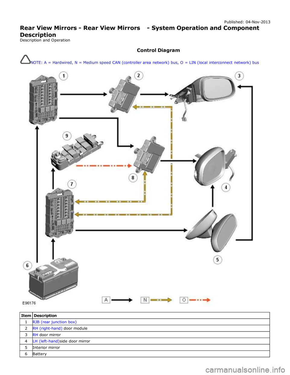
Control Diagram
NOTE: A = Hardwired, N = Medium speed CAN (controller area network) bus, O = LIN (local interconnect network) bus
Item Description 1 RJB (rear junction box) 2 RH (right-hand) door module 3 RH door mirror 4 LH (left-hand)side door mirror 5 Interior mirror 6 Battery
Page 2295 of 3039

On vehicles installed with a driver's power operated memory seat and memory exterior mirrors, a potentiometer is incorporated
within each mirror motor and is used to provide information regarding the actual motor positions. The current position and
memory positions of each door mirror motor are maintained and stored within the corresponding door control module.
The memory exterior mirror positions are also monitored and stored within door control module memory when the reverse gear
mirror dip function is used.
When reverse gear is selected, the door control module stores the current mirror positions and will then dip the passenger
mirror glass to a default dip position. While reverse gear is selected it is possible to store a preferred dipped mirror position by
adjusting the driver/passenger mirror glass to the desired position via the mirror switch pack. When the desired position is
achieved using the switch, the new dip positions will be automatically stored by the door control module when reverse gear is
de-selected. Therefore when reverse gear is re-selected, the dip position recalled by the door control module will be the new
reverse gear mirror dip stored position. When reverse gear is deselected the mirror glass will automatically move to the previous
stored position prior to reverse gear selection.
If the driver selects a memory recall function using the memory seat switch pack, the driver's memory seat and exterior
memory mirrors are moved to a stored memory position.
Exterior mirrors with the power fold/auto fold feature incorporate a motor located in the hinge of each exterior mirror arm.
Operation of the power fold feature is achieved using the exterior mirror switch pack. Operation of the auto fold feature is
achieved using the remote handset.
The power fold function is active when the ignition is in power mode 6 (Ignition).
Both exterior mirrors will power fold when the mirror switch pack 'L' and 'R' switches are pressed together. Pressing the
switches again will unfold the mirrors.
When the instrument cluster is configured for the auto fold feature, the mirrors will fold in when the remote handset lock
button is pressed. The mirrors will unfold when the vehicle is unlocked using the remote handset unlock button.
NOTE: If the mirrors are folded in using the mirror switch pack (power fold) and the vehicle is then locked, subsequent
unlocking of the vehicle will not unfold the mirrors.
When the remote handset unlock button is operated, the CJB recognizes the remote handset for that vehicle and acknowledges the request. The door control modules are connected directly to the AJB (auxiliary junction box) for power supply to the
exterior mirror folding motors.
When the vehicle is locked the door control modules reverse the polarity of the mirror fold motor, power and ground
connections to operate the mirrors in the opposite direction.
Exterior mirror heating is provided with heater elements bonded to the back of the mirror glass. Power supply for the mirror
heating elements is provided by the corresponding driver or passenger door control module via the RJB. The door control modules receive a power supply from the RJB, and are both connected on the medium speed CAN bus to the ATC (automatic temperature control) module. A ground terminal from each door control module completes the circuit. The ATC module automatically controls the mirror heating function whenever the ignition is in power mode 4 (Accessory) and power mode 6
(Ignition).
Operation of the exterior mirror heaters is fully automatic and not controllable by the driver. Exterior mirror heater operation is
determined by ambient air temperature and windshield wiper status. When ambient air temperature reaches a pre-determined
level, the ATC module broadcasts an exterior mirror heating request to the door modules over the medium speed CAN bus. On receipt of this message, the door modules provide feed and ground connections to both exterior mirror heater elements.
The mirror heating is controlled in two phases, the initial heating phase and a second PWM (pulse width modulation) controlled
phase. In the first phase the heater elements in the mirrors are permanently powered for a pre-determined length of time. This
length of time varies with the ambient temperature. During the second PWM phase, the heater elements are turned on and off every 30 seconds. The amount of time the exterior mirror heaters are operational increases if the windshield wipers are
switched on. This ensures the mirrors remain mist free in damp and wet conditions, where there is an increased risk of misting.
Page 2314 of 3039

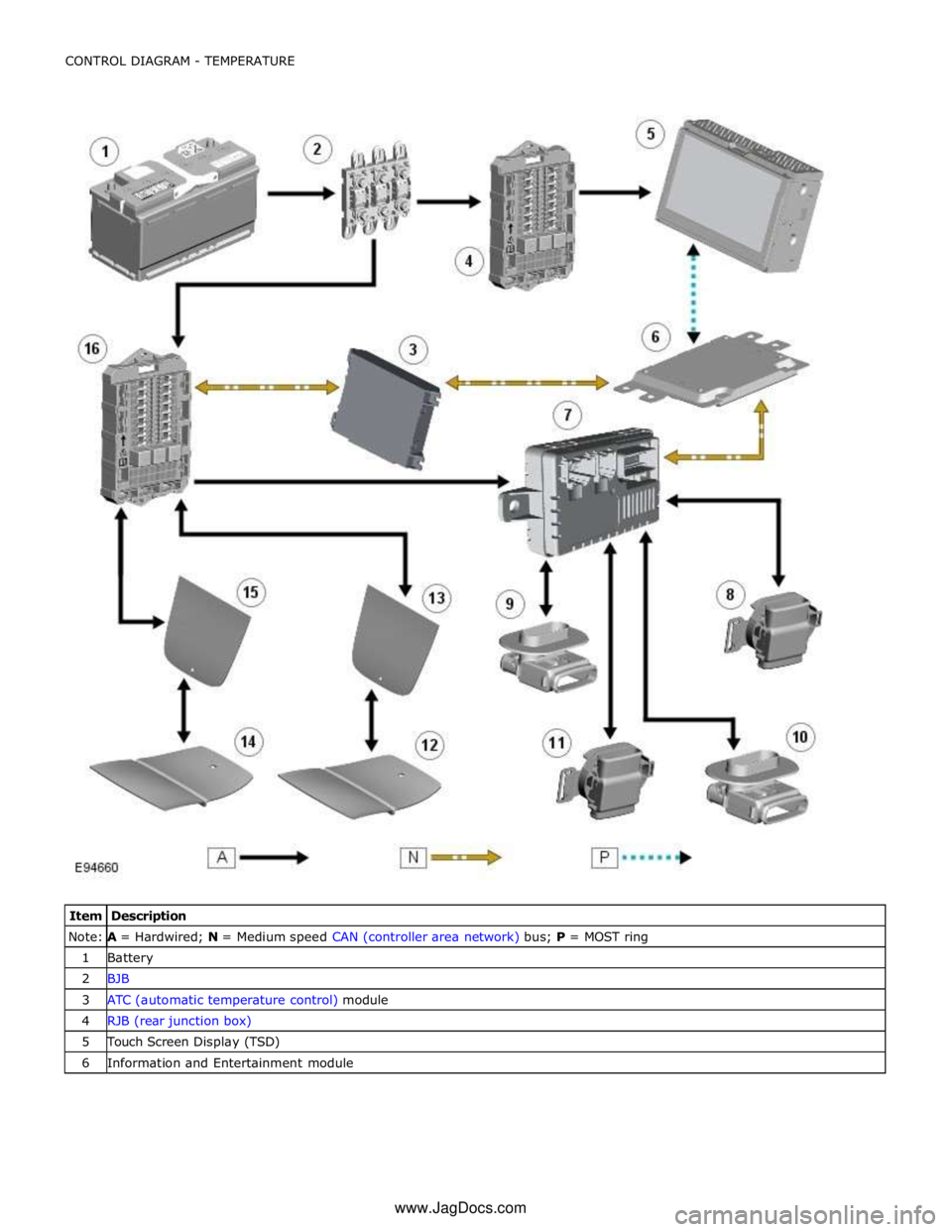
Note:
A =
Hardwired;
N
=
Medium
speed
CAN
(controller
area
network) bus;
P
=
MOST
ring
1
Battery
2
BJB
3
ATC
(automatic
temperature
control) module
4
RJB
(rear
junction
box)
5
Touch Screen
Display
(TSD)
6
Information
and
Entertainment
module
www.JagDocs.com
Page 2315 of 3039

7 Front seat climate control module 8 Passenger seat squab climate module 9 Drivers seat cushion climate module 10 Passenger seat cushion climate module 11 Drivers seat squab climate module 12 Passenger seat cushion heater element 13 Passenger seat squab heater element 14 Drivers seat cushion heater element 15 Drivers seat squab heater element 16 CJB
HEATED SEATS - OPERATION
Heated Front Seats System Operation
The TSD receives a fused power supply from the RJB. One of the 3 seat heat temperature selections made by the driver or passenger using the TSD soft keys are passed from the TSD on the MOST ring to the Information and Entertainment module.
The information and entertainment module processes the information and transmits the request on the medium speed CAN bus to the ATC module.
The cushion heaters have a thermal sensor which supplies a feed back signal back to the CJB. The squab heater elements do not have a thermal sensor and are maintained at the same temperature as the seat cushion elements.
The ATC module reacts to the driver request information received from the information and entertainment module and requests the CJB to activate the seat heaters. The CJB measures the returned temperature signals from the thermal sensors and relays the temperature signals back to the ATC module. The ATC module then uses the measured seat element temperatures to provide closed-loop control of the heater elements to maintain the temperature at one the 3 heat ranges selected.
NOTE: To prevent excessive battery discharge, the heated front seats will only operate when the engine is running.
Heated and Cooled Front Seats
The TSD receives a fused power supply from the RJB. Selections made by the driver using the TSD soft keys are passed from the TSD on the MOST ring to the Information and Entertainment module. The information and entertainment module processes
the information and transmits the request on the medium speed CAN bus to the front seat climate control module. The front seat climate control module is located beneath the RH (right-hand) front seat, on the floor cross member.
The front seat climate control module receives its power supplies from the CJB. Heating and cooling requests are generated using the soft buttons on the TSD. These requests are transmitted to the information and entertainment module over the
MOST ring. The Information and Entertainment module forwards these requests to the front seat climate control module over
the medium speed CAN bus.
The front seat climate control module supplies power to the two climate modules in each seat. The temperature sensor in each
climate module is monitored by the front seat climate control module which uses the temperature information to control the
Peltier cells accordingly and also the blower fans to distribute the heated or cooled air.
NOTE: To prevent excessive battery discharge, the heated and cooled front seats will only operate when the engine is
running.
Electric Driver's Seat Adjustment - Non-Memory Seats
The CJB supplies 3 power supplies to the driver's seat switchpack. The fused supplies provide power for the seat height and squab recline, the seat slide and seat tilt and the lumbar adjustment respectively. The CJB only provides the power to the driver's seat switch pack when the ignition is on (power mode 6).
For the seat movement motors, when the applicable switch is operated, the power is supplied to the applicable side of the
motor and the ground path is completed to operate the motor in the required direction. To move the motor in the opposite
direction the polarity is reversed.
For the lumbar adjustment, when the switch is operated in the inflate position, power is supplied to the pump motor to inflate
the lumbar support. When the switch is operated in the opposite direction, the power energizes a solenoid which in turn opens
a valve to deflate the lumbar support.
Electric Passenger Seat Adjustment ( 8, 10 and 12 way)
The CJB supplies 3 power supplies to the passenger seat switchpack. The fused supplies provide power for the seat height and squab recline, the seat slide and seat tilt and the head restraint and lumbar adjustment respectively. The CJB only provides the power to the passenger seat switch pack when the ignition is on (power mode 6).
For the seat movement and head restraint motors, when the applicable switch is operated, the power is supplied to the
applicable side of the motor and the ground path is completed to operate the motor in the required direction. To move the