2010 JAGUAR XFR rjb
[x] Cancel search: rjbPage 2329 of 3039

Symptom Possible Cause Action open circuit Seat movement and memory recall works
correctly however seat lumbar is not
working correctly
NOTE: Seat module
does not control the seat
lumbar function
Seat movement
switch to lumbar
circuits - short,
open circuit Refer to the electrical circuit diagrams and check seat
movement switch to lumbar circuits for short, open
circuit Seat movement from switch pack occurs
in delayed inch mode (seat axis moves
short distance when switch pressed for
longer than 2 seconds and then stops). This behaviour could occur on any seat
axis (slide, height, squab, tilt, headrest
or cushion) when requested
Motor Hall sensor
on affected axis is
not connected or
not receiving
expected signals Check for DTCs, B1B8731, B1B9131, B1B8931, B1B9331,
B106331, B106431. If present then check Hall sensor
feedback circuits between seat motor and seat module
and also check Hall sensor ground circuits for affected
axis. These DTCs are only logged if the axis is
attempted to be moved in both directions. When hall
sensor connection issue fixed press switch on affected
axis for longer than 2 seconds. By keeping the switch
pressed the axis movement should now operate for the
duration of switch-press. Re-calibrate affected seat Seat movement from switch pack occurs
in inch mode. When seat axis movement
is requested from the seat switch pack
the requested seat axis moves a short
distance then stops (does not include
lumbar). This behaviour will occur on ALL
seat axis (slide, height, squab, tilt
headrest and cushion) when requested.
MS CAN communication not possible
MS CAN fault Carry out CAN network integrity test using manufacturer
approved diagnostic system Seat movement from switch pack occurs
in inch mode. When seat axis movement
is requested from the seat switch pack
the requested seat axis moves a short
distance then stops (does not include
lumbar). This behaviour will occur on ALL
seat axis (slide, height, squab, tilt
headrest and cushion) when requested.
MS CAN communication not possible
Seat module is
disconnected from
the CAN Bus Check for Instrument Cluster DTC U020800 'Lost
Communication With Seat Module'. If this DTC is
present, refer to the electrical circuit diagrams and check
seat module power and ground supplies for short, open
circuit. Carry out CAN network integrity tests using the
manufacturer approved diagnostic system Seat movement from switch pack occurs
in inch mode. When seat axis movement
is requested from the seat switch pack
the requested seat axis moves a short
distance then stops (does not include
lumbar). This behaviour will occur on ALL
seat axis (slide, height, squab, tilt
headrest and cushion) when requested.
MS CAN communication not possible
Instrument cluster
is disconnected
from the CAN Bus Check for seat module DTC U015500 'Lost
Communication With Instrument Cluster'. If this DTC is
present, refer to the electrical circuit diagrams and check
instrument cluster power and ground supplies for short,
open circuit. Carry out CAN network integrity tests using
the manufacturer approved diagnostic system Seat movement from switch pack occurs
in inch mode. When seat axis movement
is requested from the seat switch pack
the requested seat axis moves a short
distance then stops (does not include
lumbar). This behaviour will occur on ALL
seat axis (slide, height, squab, tilt
headrest and cushion) when requested.
MS CAN communication not possible
Driver Door Module
is disconnected
from the CAN Bus Check for seat module DTC U019900 'Lost
Communication With Driver Door Module'. If this DTC is
present, refer to the electrical circuit diagrams and check
driver door module power and ground supplies for short,
open circuit. Carry out CAN network integrity tests using
the manufacturer approved diagnostic system Seat movement from switch pack occurs
in inch mode. When seat axis movement
is requested from the seat switch pack
the requested seat axis moves a short
distance then stops (does not include
lumbar). This behaviour will occur on ALL
seat axis (slide, height, squab, tilt
headrest and cushion) when requested.
MS CAN communication not possible
Rear Junction Box
(RJB) is
disconnected from
the CAN Bus Check for seat module DTC U014200 'Lost
Communication With RJB'. If this DTC is present, refer to
the electrical circuit diagrams and check RJB power and
ground supplies for short, open circuit. Carry out CAN
network integrity tests using the manufacturer approved
diagnostic system Seat movement from switch pack occurs
in inch mode. When seat axis movement
is requested from the seat switch pack
the requested seat axis moves a short
distance then stops (does not include
lumbar). This behaviour will occur on ALL
seat axis (slide, height, squab, tilt
headrest and cushion) when requested.
MS CAN communication not possible
Central Junction
Box (CJB) is
disconnected from
the CAN Bus Refer to the electrical circuit diagrams and check CJB
power and ground supplies for short, open circuit. Carry
out CAN network integrity tests using the manufacturer
approved diagnostic system www.JagDocs.com
Page 2333 of 3039

DTC Description Possible Cause Action B1C0024
Seat Recline Up
Switch
Signal stuck high Check for a stuck switch. Refer to the electrical circuit
diagrams and check driver seat switch pack to seat
module LIN circuit for short, open circuit and seat
recline up circuit for short to ground B1C0124
Seat Recline Down
Switch
Signal stuck high Check for a stuck switch. Refer to the electrical circuit
diagrams and check driver seat switch pack to seat
module LIN circuit for short, open circuit and check seat
recline down circuit for short to ground B1C0224 Memory Store Switch
Signal stuck high Check for a stuck switch. Refer to the electrical circuit
diagrams and check driver seat switch pack to seat
module LIN circuit for short, open circuit B1C0324 Memory #1 Switch
Signal stuck high Check for a stuck switch. Refer to the electrical circuit
diagrams and check driver seat switch pack to seat
module LIN circuit for short, open circuit B1C0424 Memory #2 Switch
Signal stuck high Check for a stuck switch. Refer to the electrical circuit
diagrams and check driver seat switch pack to seat
module LIN circuit for short, open circuit B1C0524 Memory #3 Switch
Signal stuck high Check for a stuck switch. Refer to the electrical circuit
diagrams and check driver seat switch pack to seat
module LIN circuit for short, open circuit U001088
Medium speed Can
communication Bus
Bus off Carry out any pinpoint tests associated with this DTC
using the manufacturer approved diagnostic system.
Refer to the electrical circuit diagrams and check CAN
network to climate controlled seat module for short, open circuit U014000
Lost communication
with CJB
Lost communication with CJB Carry out any pinpoint tests associated with this DTC
using the manufacturer approved diagnostic system.
Check CJB for related DTCs and refer to the relevant
DTC Index U014200
Lost communication
with RJB
Lost communication with RJB Carry out any pinpoint tests associated with this DTC
using the manufacturer approved diagnostic system.
Check RJB for related DTCs and refer to the relevant
DTC Index U015500
Lost
communications
with instrument
cluster
Lost communications with
instrument cluster Carry out any pinpoint tests associated with this DTC
using the manufacturer approved diagnostic system.
Refer to the electrical circuit diagrams and check CAN
network to climate controlled seat module and
instrument cluster for short, open circuit U019900
Lost communication
with Driver Door
Module (DDM)
Lost communication with DDM Carry out any pinpoint tests associated with this DTC
using the manufacturer approved diagnostic system U030000
Internal control
module software
incompatibility
Invalid configuration message is
received Re-configure the RJB using the manufacturer approved
diagnostic system. Clear the DTC and retest. If the DTC
is still logged suspect the DSM/PSM, refer to the new
module installation note at the top of the DTC Index U1A1449
CAN Initialisation
failure
Internal electronic failure Install a new DSM, refer to the new module installation
note at the top of the DTC Index U1A4C68
Build/end of line
mode active
Manufacturing mode has not
been removed Place DSM in to customer mode using manufacturer
approved diagnostic system U300049 Control module
Internal electronic failure Install a new DSM, refer to the new module installation
note at the top of the DTC Index U300055
Stored vehicle
configuration data
does not match
Incorrect car configuration data
received Re-configure the RJB using the manufacturer approved
diagnostic system. Clear DTC and re-test. If the DTC
remains suspect the DSM, refer to the new module
installation note at the top of the DTC Index U300087 Control Module
Missing message Re-configure the RJB using the manufacturer approved
diagnostic system. Check DSM for DTCs and refer to the
DTC Index. Check CAN network integrity using the
manufacturer approved diagnostic system U300146
Control module
improper shutdown
Calibration/parameter memory
failure Check for DTCs that could indicate power failure to the
module and refer to the DTC Index U300281
Vehicle
Identification
Number (VIN)
Vehicle/component mis-match.
Corrupt VIN data being
transmitted, module previously
installed to other vehicle Install original module, check for DTCs and refer to
relevant DTC Index U300316 Battery Voltage
Circuit voltage below threshold Carry out any pinpoint tests associated with this DTC
using the manufacturer approved diagnostic system
Page 2414 of 3039
Published: 24-Jan-2013
Glass, Frames and Mechanisms - Glass, Frames and Mechanisms - System
Operation and Component Description
Description and Operation
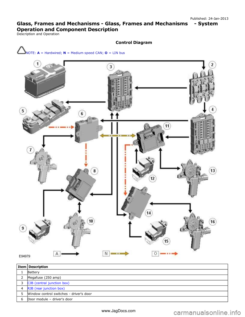
Control Diagram
NOTE: A = Hardwired; N = Medium speed CAN; O = LIN bus
Item Description 1 Battery 2 Megafuse (250 amp) 3 CJB (central junction box) 4 RJB (rear junction box) 5 Window control switches - driver's door 6 Door module – driver's door www.JagDocs.com
Page 2488 of 3039
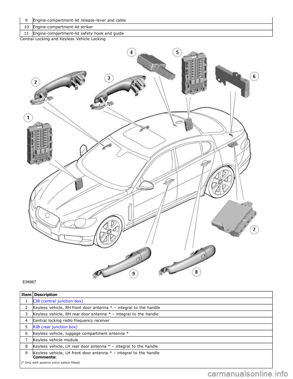
10 Engine-compartment-lid striker 11 Engine-compartment-lid safety hook and guide Central Locking and Keyless Vehicle Locking
Item Description 1 CJB (central junction box) 2 Keyless vehicle, RH front door antenna * – integral to the handle 3 Keyless vehicle, RH rear door antenna * – integral to the handle 4 Central locking radio frequency receiver 5 RJB (rear junction box) 6 Keyless vehicle, luggage compartment antenna * 7 Keyless vehicle module 8 Keyless vehicle, LH rear door antenna * – integral to the handle 9 Keyless vehicle, LH front door antenna * – integral to the handle Comments:
(* Only with passive entry option fitted)
Page 2490 of 3039
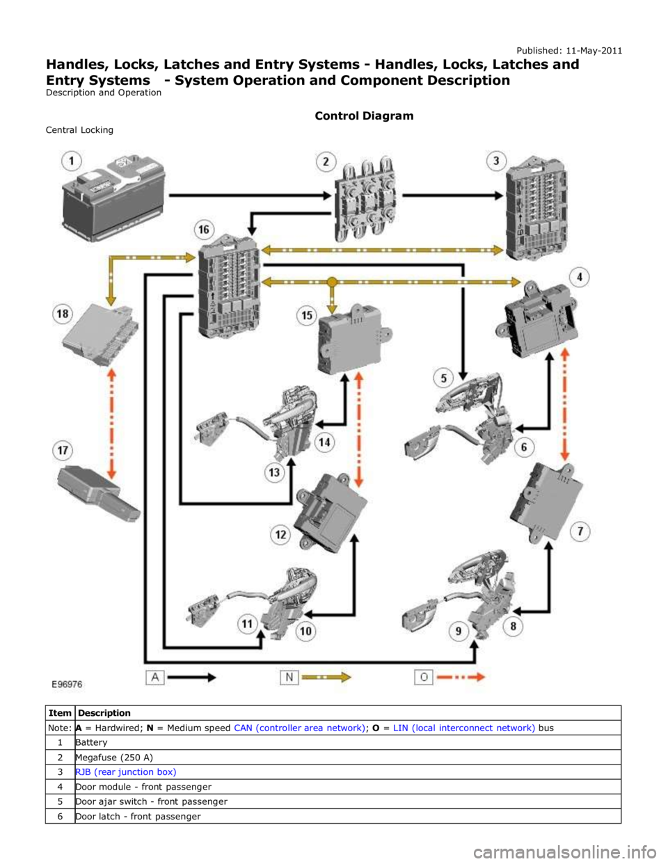
Note: A = Hardwired; N = Medium speed CAN (controller area network); O = LIN (local interconnect network) bus 1 Battery 2 Megafuse (250 A) 3 RJB (rear junction box) 4 Door module - front passenger 5 Door ajar switch - front passenger 6 Door latch - front passenger
Page 2492 of 3039
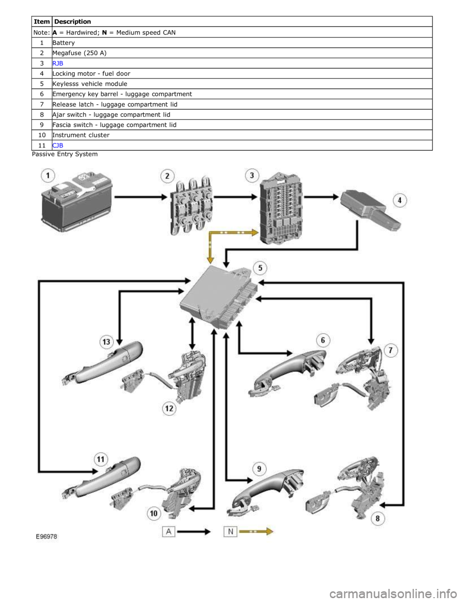
Note: A = Hardwired; N = Medium speed CAN 1 Battery 2 Megafuse (250 A) 3 RJB 4 Locking motor - fuel door 5 Keylesss vehicle module 6 Emergency key barrel - luggage compartment 7 Release latch - luggage compartment lid 8 Ajar switch - luggage compartment lid 9 Fascia switch - luggage compartment lid 10 Instrument cluster 11 CJB Passive Entry System
Page 2494 of 3039

door modules.
Locking of the vehicle is performed by pressing one of the buttons located on each exterior door handle, with the Smart Key
within a one meter range of the vehicle. When the door handle button is pressed, the keyless vehicle module transmits a
low-frequency signal via the low-frequency handle antenna to the Smart Key. The Smart Key transmits a radio frequency signal
which is verified by the keyless vehicle module and allows the doors to be locked or double locked and the alarm system to be
armed.
To double lock the vehicle, the button on the exterior door handle must be pressed twice within three seconds, with the Smart
Key within one meter range of the vehicle.
If a door, engine-compartment lid or the luggage compartment lid is ajar when an attempt to lock the vehicle is made, an error
tone is emitted and no locking action will occur.
Refer to: Anti-Theft - Active (419-01A Anti-Theft - Active, Description and Operation).
Engine Compartment Lid Latches Component Description
Two engine-compartment lid latches are located on the front crossmember. An engine-compartment lid release lever is located
below the instrument panel on the left-hand 'A' pillar and is connected with a cable to the latches. An engine-compartment lid
ajar switch is integrated in the engine-compartment lid latch.
Door Latches
The door latches are located at the rear of each door and engage with a striker on the adjacent pillar. Each door latch motor
assembly contains micro-switches for lock, unlock and door ajar. Motors provide for the central door locking and the double
locking feature. The electrical control for the door latch components is provided by the CJB and RJB via the driver's and
passenger door modules.
The interior door handles are connected by a cable to the latch release mechanisms. The interior door handles also incorporate
a locking facility to allow the doors to be locked from inside the vehicle when all the doors are closed. If a door is ajar the
locking feature is inhibited.
Luggage Compartment Lid Latch
The luggage compartment latch is attached to the bottom of the lid. The latch can be released electrically by pressing the
interior release button located on the outboard side of driver's lower knee bolster; a release button is also provided on the
Smart Key. There is also a release switch on the underside of the luggage compartment lid finisher.
On NAS vehicles an emergency release cable is attached to the latch. This allows the latch to be manually opened by pulling a
handle located in the luggage compartment lid interior trim.
Fuel Filler Door
The fuel filler door is electrically locked by a motor located on the fuel door housing. The fuel door is locked when the vehicle
is locked and alarmed. The fuel door can be opened when the vehicle is unlocked or locked:
via an interior handle,
via drive-a-way locking,
via the lock switch on the fascia,
via the external door key barrel. www.JagDocs.com
Page 2612 of 3039
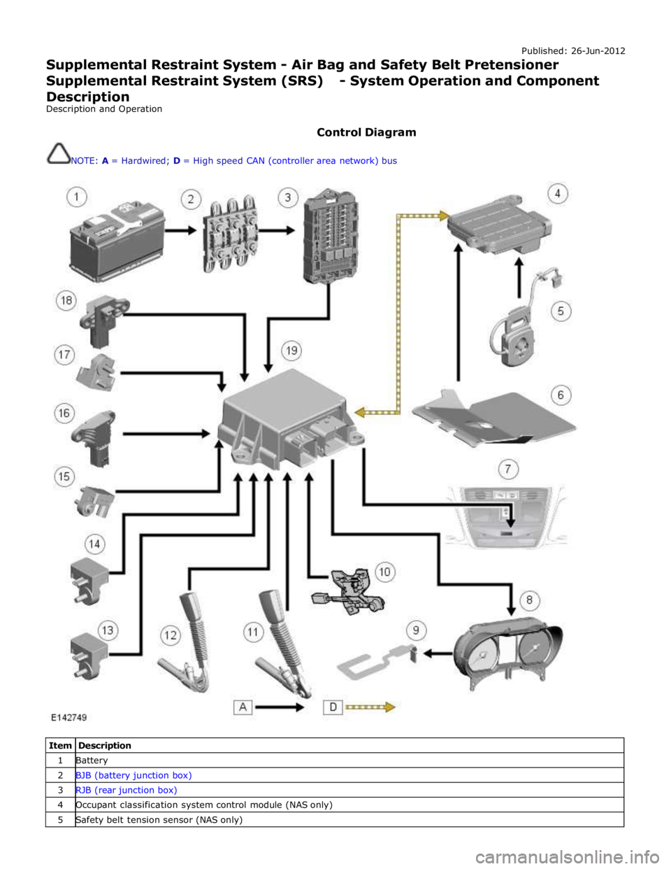
Published: 26-Jun-2012
Supplemental Restraint System - Air Bag and Safety Belt Pretensioner
Supplemental Restraint System (SRS) - System Operation and Component Description
Description and Operation
Control Diagram
NOTE: A = Hardwired; D = High speed CAN (controller area network) bus
Item Description 1 Battery 2 BJB (battery junction box) 3 RJB (rear junction box) 4 Occupant classification system control module (NAS only) 5 Safety belt tension sensor (NAS only)