2010 JAGUAR XFR key
[x] Cancel search: keyPage 2178 of 3039
Published: 11-May-2011
Multifunction Electronic Modules - Remote Keyless Entry (RKE) Module
Diagnosis and Testing
Principles of Operation
For a detailed description of the Remote Keyless Entry system, refer to the relevant Description and Operation sections in the
workshop manual. REFER to: (419-10 Multifunction Electronic Modules)
Module Controlled Functions (Description and Operation), Module Controlled Functions (Description and Operation), Module Controlled Functions (Description and Operation).
Inspection and Verification
CAUTION: Diagnosis by substitution from a donor vehicle is NOT acceptable. Substitution of control modules does not
guarantee confirmation of a fault, and may also cause additional faults in the vehicle being tested and/or the donor vehicle.
1. Verify the customer concern.
2. Visually inspect for obvious signs of damage and system integrity.
Visual Inspection
Mechanical Electrical
Misaligned door(s), hood or luggage compartment lid
Door latch(s)
Actuating rod(s)
Exterior door handle(s)
Interior door handle(s)
Door lock cylinder
Cable(s)
Luggage compartment lid exterior release switch
Fuse(s)
Wiring harness
Electrical connector(s)
Door lock actuator(s)
Remote transmitter batteries
Vehicle battery
Remote transmitter
Door lock switch(s)
3. If an obvious cause for an observed or reported concern is found, correct the cause (if possible) before proceeding to
the next step.
4. If the cause is not visually evident, check for Diagnostic Trouble Codes (DTCs) and refer to the DTC Index.
DTC Index
CAUTION: When probing connectors to take measurements in the course of the pinpoint tests, use the adaptor kit, part
number 3548-1358-00.
NOTES:
If the control module or a component is suspect and the vehicle remains under manufacturer warranty, refer to the
Warranty Policy and Procedures manual (section B1.2), or determine if any prior approval programme is in operation, prior to
the installation of a new module/component.
Generic scan tools may not read the codes listed, or may read only five digit codes. Match the five digits from the scan
tool to the first five digits of the seven digit code listed to identify the fault (the last two digits give additional information
read by the manufacturer approved diagnostic system).
When performing electrical voltage or resistance tests, always use a digital multimeter (DMM) accurate to three decimal
places, and with an up-to-date calibration certificate. When testing resistance, always take the resistance of the DMM leads
into account.
Check and rectify basic faults before beginning diagnostic routines involving pinpoint tests.
Inspect connectors for signs of water ingress, and pins for damage and/or corrosion.
If DTCs are recorded and, after performing the pinpoint tests, a fault is not present, an intermittent concern may be the
cause. Always check for loose connections and corroded terminals.
Page 2179 of 3039

DTC Description Possible Cause Action B102B00 Passive Key
Response Error - general
failure Using the manufacturer approved diagnostic system, clear
all passive keys, re-learn all passive keys B10C100
Left Front Unlock Pull
Switch
No subtype information Carry out any pinpoint tests associated with this DTC using
the manufacturer approved diagnostic system B10C124
Left Front Unlock Pull
Switch
Signal stuck high - button
stuck in active position Carry out any pinpoint tests associated with this DTC using
the manufacturer approved diagnostic system. Check for
stuck left front unlock switch. Refer to the electrical circuit
diagrams and check left front unlock switch circuit for short
to ground B10C200
Left Rear Unlock Pull
Switch
No subtype information Carry out any pinpoint tests associated with this DTC using
the manufacturer approved diagnostic system B10C224
Left Rear Unlock Pull
Switch
Signal stuck high - button
stuck in active position Carry out any pinpoint tests associated with this DTC using
the manufacturer approved diagnostic system. Check for
stuck left rear unlock switch. Refer to the electrical circuit
diagrams and check left rear unlock switch circuit for short
to ground B10C300
Right Front Unlock
Pull Switch
No subtype information Carry out any pinpoint tests associated with this DTC using
the manufacturer approved diagnostic system B10C324
Right Front Unlock
Pull Switch
Signal stuck high - button
stuck in active position Carry out any pinpoint tests associated with this DTC using
the manufacturer approved diagnostic system. Check for
stuck right front unlock switch. Refer to the electrical circuit
diagrams and check right front unlock switch circuit for
short to ground B10C400
Right Rear Unlock Pull
Switch
No subtype information Carry out any pinpoint tests associated with this DTC using
the manufacturer approved diagnostic system B10C424
Right Rear Unlock Pull
Switch
Signal stuck high - button
stuck in active position Carry out any pinpoint tests associated with this DTC using
the manufacturer approved diagnostic system. Check for
stuck right rear unlock switch. Refer to the electrical circuit
diagrams and check right front unlock switch circuit for
short to ground B10C524 Trunk Unlock Pull
Switch
Signal stuck high - button
stuck in active position Carry out any pinpoint tests associated with this DTC using
the manufacturer approved diagnostic system. Check for
stuck luggage compartment lid unlock switch. Refer to the
electrical circuit diagrams and check luggage compartment
lid unlock switch circuit for short to ground B10C61F
Exterior Trunk
Antenna
Circuit intermittent -
general electrical error Carry out any pinpoint tests associated with this DTC using
the manufacturer approved diagnostic system. Refer to the
electrical circuit diagrams and check exterior luggage
compartment antenna circuits for short to ground, power, open circuit B10C71F
Interior Trunk
Antenna
Circuit intermittent -
general electrical error Carry out any pinpoint tests associated with this DTC using
the manufacturer approved diagnostic system. Refer to the
electrical circuit diagrams and check interior luggage
compartment antenna circuits for short to ground, power, open circuit B10C81F
Interior Center
Antenna
Circuit intermittent -
general electrical error Carry out any pinpoint tests associated with this DTC using
the manufacturer approved diagnostic system. Refer to the
electrical circuit diagrams and check interior center antenna
circuits for short to ground, power, open circuit B10C91F Interior Front Antenna
Circuit intermittent -
general electrical error Carry out any pinpoint tests associated with this DTC using
the manufacturer approved diagnostic system. Refer to the
electrical circuit diagrams and check interior front antenna
circuits for short to ground, power, open circuit B10CA1F
Left Rear Door Handle
Antenna
Circuit intermittent -
general electrical error Carry out any pinpoint tests associated with this DTC using
the manufacturer approved diagnostic system. Refer to the
electrical circuit diagrams and check left rear door handle
antenna circuits for short to ground, power, open circuit B10CB1F
Right Rear Door
Handle Antenna
Circuit intermittent -
general electrical error Carry out any pinpoint tests associated with this DTC using
the manufacturer approved diagnostic system. Refer to the
electrical circuit diagrams and check right rear door handle
antenna circuits for short to ground, power, open circuit B10CC24
Left Front Latch
Clutch Switch
Signal stuck high - button
stuck in active position Check for stuck left front door latch clutch switch. Refer to
the electrical circuit diagrams and check left front door
latch clutch switch circuit for short to ground B10CD24
Left Rear Latch Clutch
Switch
Signal stuck high - button
stuck in active position Check for stuck left rear door latch clutch switch. Refer to
the electrical circuit diagrams and check left rear door latch
clutch switch circuit for short to ground
Page 2180 of 3039

DTC Description Possible Cause Action B10CE24
Right Front Latch
Clutch Switch
Signal stuck high - button
stuck in active position Check for stuck right front door latch clutch switch. Refer to
the electrical circuit diagrams and check right front door
latch clutch switch circuit for short to ground B10CF24
Right Rear Latch
Clutch Switch
Signal stuck high - button
stuck in active position Check for stuck right rear door latch clutch switch. Refer to
the electrical circuit diagrams and check right rear door
latch clutch switch circuit for short to ground B10D124 Left Front Lock Button
Signal stuck high - button
stuck in active position Check for stuck left front door handle lock switch. Refer to
the electrical circuit diagrams and check left front door
handle lock switch circuit for short to ground B10D224 Left Rear Lock Button
Signal stuck high - button
stuck in active position Check for stuck left rear door handle lock switch. Refer to
the electrical circuit diagrams and check left rear door
handle lock switch circuit for short to ground B10D324
Right Front Lock
Button
Signal stuck high - button
stuck in active position Check for stuck right front door handle lock switch. Refer to
the electrical circuit diagrams and check right front door
handle lock switch circuit for short to ground B10D424
Right Rear Lock
Button
Signal stuck high - button
stuck in active position Check for stuck right rear door handle lock switch. Refer to
the electrical circuit diagrams and check left front door
handle lock switch circuit for short to ground U001000
Medium Speed CAN
Communication Bus
No subtype information Carry out any pinpoint tests associated with this DTC using
the manufacturer approved diagnostic system. Carry out
CAN network integrity test using the manufacturer approved diagnostic system U014000
Lost Communication
With Body Control
Module
Missing message from CJB Carry out any pinpoint tests associated with this DTC using
the manufacturer approved diagnostic system. Carry out
CAN network integrity test using the manufacturer
approved diagnostic system. Refer to the electrical circuit diagrams and check power and ground supplies to CJB U014200
Lost Communication
With Body Control
Module "B"
Missing message from RJB Carry out any pinpoint tests associated with this DTC using
the manufacturer approved diagnostic system. Carry out
CAN network integrity test using the manufacturer
approved diagnostic system. Refer to the electrical circuit diagrams and check power and ground supplies to RJB U015500
Lost Communication
With Instrument
Panel Cluster (IPC)
Control Module
Missing message from
instrument cluster Carry out any pinpoint tests associated with this DTC using
the manufacturer approved diagnostic system. Carry out
CAN network integrity test using the manufacturer
approved diagnostic system. Refer to the electrical circuit
diagrams and check power and ground supplies to
instrument cluster U030000
Internal Control
Module Software
Incompatibility
Invalid configuration
message is received Re-configure the RJB using the manufacturer approved
diagnostic system. Clear the DTC and retest. If the DTC is
still logged suspect the remote keyless entry module, refer
to the new module installation note at the top of the DTC
Index U201F00 External Receiver
No subtype information -
communication error Suspect the RF receiver, check and install a new RF receiver
as required, refer to the new module/component
installation note at top of DTC Index U201F13 External Receiver
Line open Refer to the electrical circuit diagrams and test RF receiver
communication circuit to remote keyless entry module for
short to ground or open circuit U201F87 External Receiver
Transmission error Refer to the electrical circuit diagrams and check the data
line between the RF receiver and the remote keyless entry
module for short, open circuit. Suspect the RF receiver or
remote keyless entry module, check and install a new RF
receiver or remote keyless entry module as required, refer
to the new module/component installation note at top of
DTC Index U210000
Initial Configuration
Not Complete
No subtype information Configure the Remote Keyless Entry module using the
manufacturer approved diagnostic system U210100
Control Module
Configuration Incompatible
No subtype information Re-configure the RJB using the manufacturer approved
diagnostic system U300049 Control Module
Internal electronic failure Install a new remote keyless entry module, refer to the
new module installation note at the top of the DTC Index U300281
Vehicle Identification
Number
Vehicle/component
mis-match. Module
previously installed to other
vehicle Install correct/new module to vehicle specification, refer to
the new module/component installation note at the top of
the DTC Index www.JagDocs.com
Page 2181 of 3039

DTC Description Possible Cause Action U300362 Battery Voltage
Mis-match in battery
voltage, of 2 volts or more,
between remote keyless
entry module and RJB Carry out any pinpoint tests associated with this DTC using
the manufacturer approved diagnostic system
Page 2315 of 3039
7 Front seat climate control module 8 Passenger seat squab climate module 9 Drivers seat cushion climate module 10 Passenger seat cushion climate module 11 Drivers seat squab climate module 12 Passenger seat cushion heater element 13 Passenger seat squab heater element 14 Drivers seat cushion heater element 15 Drivers seat squab heater element 16 CJB
HEATED SEATS - OPERATION
Heated Front Seats System Operation
The TSD receives a fused power supply from the RJB. One of the 3 seat heat temperature selections made by the driver or passenger using the TSD soft keys are passed from the TSD on the MOST ring to the Information and Entertainment module.
The information and entertainment module processes the information and transmits the request on the medium speed CAN bus to the ATC module.
The cushion heaters have a thermal sensor which supplies a feed back signal back to the CJB. The squab heater elements do not have a thermal sensor and are maintained at the same temperature as the seat cushion elements.
The ATC module reacts to the driver request information received from the information and entertainment module and requests the CJB to activate the seat heaters. The CJB measures the returned temperature signals from the thermal sensors and relays the temperature signals back to the ATC module. The ATC module then uses the measured seat element temperatures to provide closed-loop control of the heater elements to maintain the temperature at one the 3 heat ranges selected.
NOTE: To prevent excessive battery discharge, the heated front seats will only operate when the engine is running.
Heated and Cooled Front Seats
The TSD receives a fused power supply from the RJB. Selections made by the driver using the TSD soft keys are passed from the TSD on the MOST ring to the Information and Entertainment module. The information and entertainment module processes
the information and transmits the request on the medium speed CAN bus to the front seat climate control module. The front seat climate control module is located beneath the RH (right-hand) front seat, on the floor cross member.
The front seat climate control module receives its power supplies from the CJB. Heating and cooling requests are generated using the soft buttons on the TSD. These requests are transmitted to the information and entertainment module over the
MOST ring. The Information and Entertainment module forwards these requests to the front seat climate control module over
the medium speed CAN bus.
The front seat climate control module supplies power to the two climate modules in each seat. The temperature sensor in each
climate module is monitored by the front seat climate control module which uses the temperature information to control the
Peltier cells accordingly and also the blower fans to distribute the heated or cooled air.
NOTE: To prevent excessive battery discharge, the heated and cooled front seats will only operate when the engine is
running.
Electric Driver's Seat Adjustment - Non-Memory Seats
The CJB supplies 3 power supplies to the driver's seat switchpack. The fused supplies provide power for the seat height and squab recline, the seat slide and seat tilt and the lumbar adjustment respectively. The CJB only provides the power to the driver's seat switch pack when the ignition is on (power mode 6).
For the seat movement motors, when the applicable switch is operated, the power is supplied to the applicable side of the
motor and the ground path is completed to operate the motor in the required direction. To move the motor in the opposite
direction the polarity is reversed.
For the lumbar adjustment, when the switch is operated in the inflate position, power is supplied to the pump motor to inflate
the lumbar support. When the switch is operated in the opposite direction, the power energizes a solenoid which in turn opens
a valve to deflate the lumbar support.
Electric Passenger Seat Adjustment ( 8, 10 and 12 way)
The CJB supplies 3 power supplies to the passenger seat switchpack. The fused supplies provide power for the seat height and squab recline, the seat slide and seat tilt and the head restraint and lumbar adjustment respectively. The CJB only provides the power to the passenger seat switch pack when the ignition is on (power mode 6).
For the seat movement and head restraint motors, when the applicable switch is operated, the power is supplied to the
applicable side of the motor and the ground path is completed to operate the motor in the required direction. To move the
Page 2376 of 3039
Seating - Seat Base
Removal and Installation
Removal
WARNINGS: Published: 11-May-2011
To avoid accidental deployment, the restraints control module backup power supply must be depleted. Wait at least one
minute after disconnecting the battery ground cable(s) before commencing any repair or adjustment to the supplemental
restraint system (SRS), or any component(s) adjacent to the SRS sensors. Failure to follow these instructions may result in
personal injury.
Always wear safety glasses when working on an air bag equipped vehicle and when handling an air bag module. Failure to
follow this instruction may result in personal injury.
To minimize the possibility of premature deployment, do not use radio key code savers when working on the
supplemental restraint system. Failure to follow this instruction may result in personal injury.
To minimize the possibility of injury in the event of premature deployment, always carry a live air bag module with the
bag and trim cover pointed away from the body. Failure to follow this instruction may result in personal injury.
To minimize the possibility of premature deployment, live air bag modules must only be placed on work benches which
have been ground bonded and with the trim cover facing up. Failure to follow these instructions may result in personal injury.
Never probe the electrical connectors of air bag modules or any other supplemental restraint system component. Failure
to follow this instruction may result in personal injury.
Painting over the driver air bag module trim cover or instrument panel could lead to deterioration of the trim cover and air
bags. Do not for any reason attempt to paint discolored or damaged air bag module trim covers or instrument panel. Install a
new component. Failure to follow this instruction may result in personal injury.
NOTES:
Some variation in the illustrations may occur, but the essential information is always correct.
Removal steps in this procedure may contain installation details.
1. Make the air bag supplemental restraint system (SRS) safe.
Refer to: Standard Workshop Practices (100-00 General Information, Description and Operation).
2. Refer to: Front Seat (501-10 Seating, Removal and Installation).
3. Refer to: Front Safety Belt Buckle (501-20A Safety Belt System, Removal and Installation).
4. Refer to: Front Seat Cushion Cover (501-10 Seating, Removal and Installation).
Page 2487 of 3039
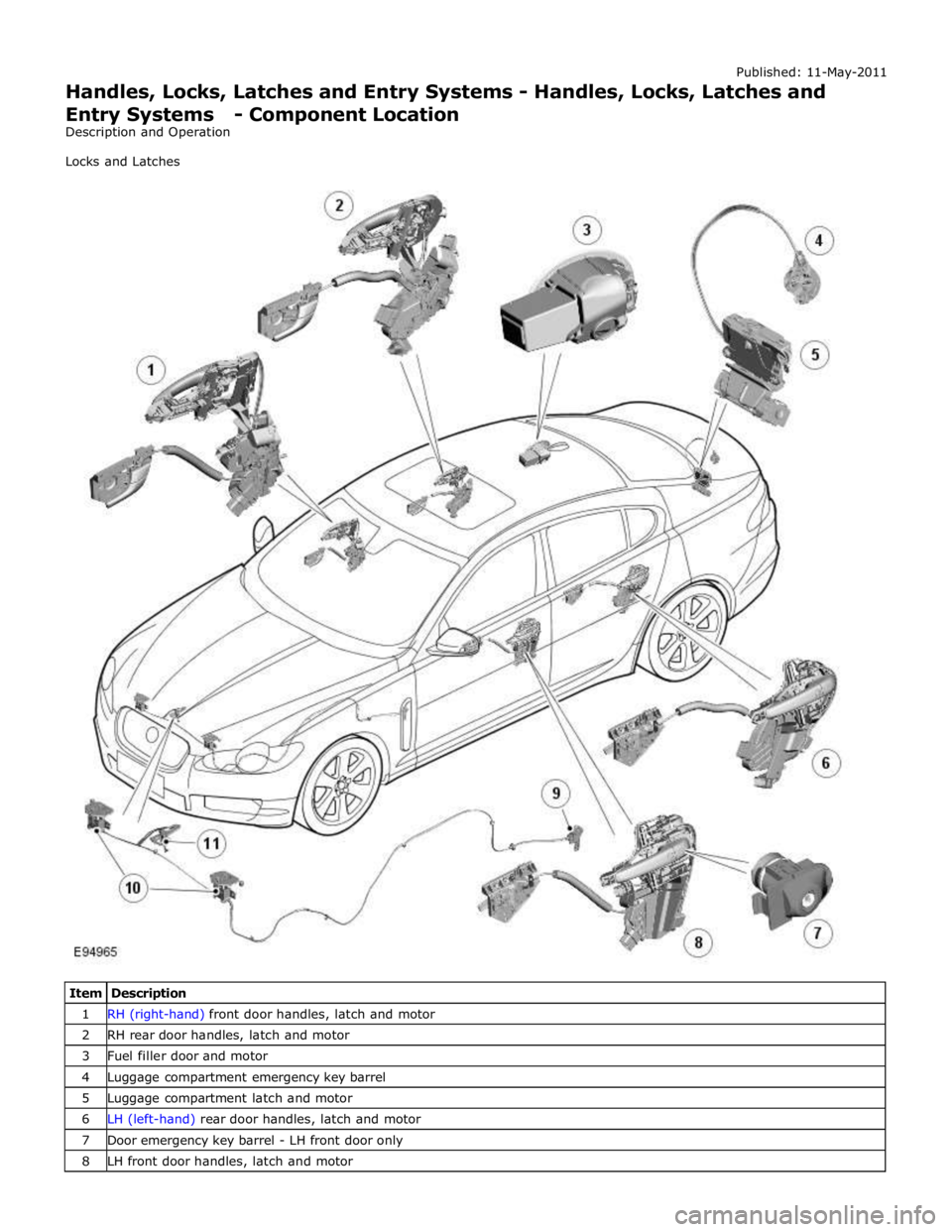
1 RH (right-hand) front door handles, latch and motor 2 RH rear door handles, latch and motor 3 Fuel filler door and motor 4 Luggage compartment emergency key barrel 5 Luggage compartment latch and motor 6 LH (left-hand) rear door handles, latch and motor 7 Door emergency key barrel - LH front door only 8 LH front door handles, latch and motor
Page 2488 of 3039
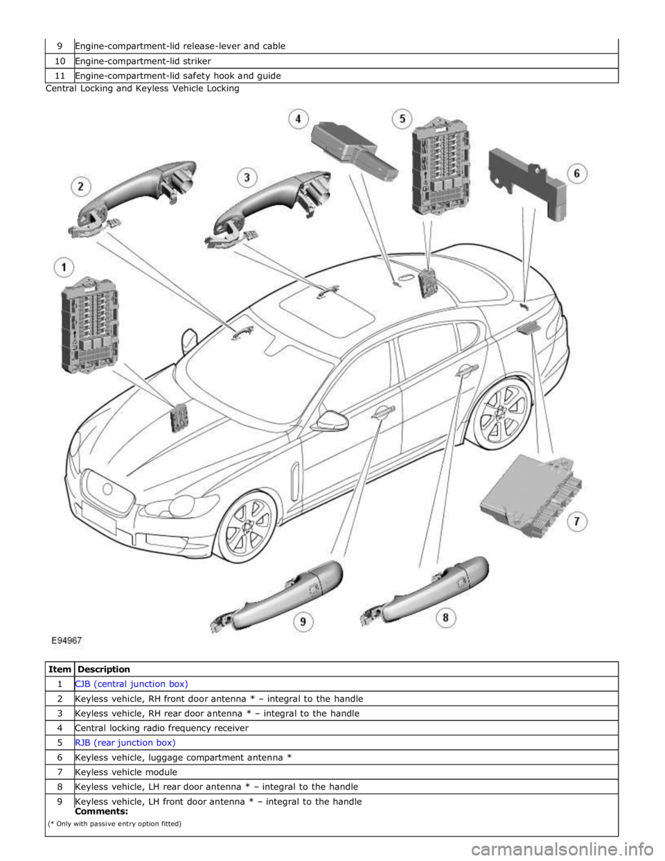
10 Engine-compartment-lid striker 11 Engine-compartment-lid safety hook and guide Central Locking and Keyless Vehicle Locking
Item Description 1 CJB (central junction box) 2 Keyless vehicle, RH front door antenna * – integral to the handle 3 Keyless vehicle, RH rear door antenna * – integral to the handle 4 Central locking radio frequency receiver 5 RJB (rear junction box) 6 Keyless vehicle, luggage compartment antenna * 7 Keyless vehicle module 8 Keyless vehicle, LH rear door antenna * – integral to the handle 9 Keyless vehicle, LH front door antenna * – integral to the handle Comments:
(* Only with passive entry option fitted)