2010 JAGUAR XFR tires
[x] Cancel search: tiresPage 1792 of 3039

Specific warning lamp
'ON' C–1
Check with IDS for DTCs related to
identified vehicle system. . . C–2
Check for open circuit/shorts in wiring
related to warning lamp circuit (module,
sensor, switch) where appropriate. . . C–3
Perform cluster Self-Diagnostic Mode/ETM
test 3. Frost/ice warning illuminated in mixed red and
amber; therefore colour differs from other
warning lamps. When this test is ended,
warning lamps currently required to be 'ON' will
remain illuminated. . C–4
Check the specific vehicle system
indicated by the warning lamp
illuminated? What is the warning lamp telling me? Does this
check out with the DTC logged by the system indicating the fault? Fuel gauge operation D–1
Perform Self-Diagnostic Mode/ETM test 21
to establish if fuel level input to cluster is
out of range or invalid. 0 - 9 = short circuit; gauge will show empty. 10
– 254 = normal range. 255 = open circuit;
gauge will show empty. --- = missing signal; gauge will show empty. . D–2
Check gauge function versus
Self-Diagnostic Mode/ETM test 21. 0 = empty, 254 = full. 255 = invalid; gauge will
show empty. . D–3
Check for open circuit/shorts in wiring
between the Fuel Delivery Module, Jet
Pump Module and Rear Electronic Module (REM). . Fuel gauge reading E–1
Check gauge position versus
Self-Diagnostic Mode/ETM test 21. 0 = empty to 254 = full (255 invalid; gauge will
show empty). Other values percentage of above range e.g. 127 = half. . E–2
Calculate percentage fuel level from figure
obtained from Self-Diagnostic Mode/ETM
test 21 and compare to IDS vehicle fuel percentage test. Self-Diagnostic Mode fuel level percentage can
be calculated as follows: Value from
Self-Diagnostic Mode test 26 ÷ 254 x 100 = %
shown on gauge. . E–3
Monitor value of Self-Diagnostic Mode
test/ETM test 21 (during test drive) to
establish if input drops out of range. 0 - 9 = short circuit; gauge will show empty. 10
– 254 = normal range. 255 = open circuit;
gauge will show empty. --- = missing signal; gauge will show empty. . E–4
Monitor 'FUEL LEVEL' in IDS data logger
(during test drive) to correlate gauge position to vehicle reported fuel level. Gauge function is damped so will not follow
rapidly changing Fuel Delivery Module values. Speedometer
operation H–1
Monitor Self-Diagnostic Mode/ETM test 19
(during test drive) check to establish if
vehicle speed input to cluster is out of range or invalid. Display speed input in 1/10 mile/h, no decimal
point shown, and is compensated for tire size
etc. Displays ---- or INV if message is not
received or if received data is invalid. Speedometer reading I–1
During test drive compare speedometer
position to Self-Diagnostic Mode/ETM test
19, displayed value. Self-Diagnostic Mode displayed speed figure will
be approx 3% higher than speed indicated by
speedometer. Allowed tolerance – minus nothing/+ 10% + 2.5 mile/h. . I–2
Monitor Self-Diagnostic Mode/ETM test 19
(during test drive) to establish if vehicle
speed input to cluster drops out of range
or is invalid. Displays ---- if message is not received or if
received data is invalid for two seconds or more. . I–3
Check that installed wheels and tires are
standard Jaguar fitment. Confirm wheel
size in IDS, 'ADD REMOVE ACCESSORY'
section. Non standard wheels and tires may lead to
speed indication inaccuracies. Incorrectly set
wheel size will result in speed indication
inaccuracies. Trip and odometer distance
accumulation will also be incorrect. Tachometer operation J–1
Perform Self-Diagnostic Mode/ETM test 20
to establish if vehicle rpm input to cluster
out of range or invalid. Displays ---- or INV if message is not received
or if received data is invalid. Tachometer reading K–1
Check tachometer position versus
Self-Diagnostic Mode/ETM test 20, displayed value. Tachometer accuracy +/- 100 rpm. . K–2
Monitor 'ENGINE RPM' in IDS data logger
at constant engine rpm to compare
tachometer indicated engine rpm to
engine rpm reported by Engine Control
Module (ECM). Tachometer accuracy +/- 100 rpm. . K–3
Monitor Self-Diagnostic Mode test/ETM
test 20, (during test drive) to establish if
input to cluster drops out of range or is
invalid. Displays ---- or INV if message is not received
or if received data is invalid. Gauge judder L–1
Perform Self-Diagnostic Mode test/ETM
test 2, to prove out smooth gauge operation. . Gauge noise M–1
Perform vehicle road test. Gauges should
not be audible during operation in drive cycle. . www.JagDocs.com
Page 1793 of 3039

. M–2
Benchmark noise against non-complaint
vehicle. . Trip (fuel) computer N–1
Check for consistent display (during test
drive) of valid 'Rolling Odometer' count in
Self-Diagnostic Mode/ETM test 24. Displays ---- , INV or 255 if message is not
received, or if received data is invalid. . N–2
Check that installed wheels and tires are
standard Jaguar fit. Confirm fitted wheel
size in IDS, 'ADD REMOVE ACCESSORY'
section. Non standard wheels and tires or incorrectly set
wheel size may lead to Odometer increment
inaccuracies. This will impact the distance
accumulators, which in turn affects the rolling
average, fuel economy and range values. Trip
distance accumulation will also be incorrect. . N–3
Consider noting odometer value and
resetting fuel computer system. Advise
customer to conduct brim-to-brim fuel
tank test. Use collected information to
determine if system accurate. . Column adjust O-1
Check with IDS for DTCs related to powered column system. . O-2
Check cluster battery supply voltage and
ground resistance. Check for loose
connections. . O-3
Check power column motors supply voltage. . O-4
Check power column switch for physical damage. . Passive Anti-Theft
System (PATS)
indicator P–1
Check for three second prove out when
vehicle start button is pressed. . . P–2
Check for loose connections/wiring continuity. . . P–3 Check ignition switch for physical damage. . Cluster illumination Q–1
Check for loose connections/wiring continuity. . . Q–2 Check dimmer switch operation. . Cluster backlight operation R–1
Is the backlight on other components inoperative. . . R–2 Check dimmer switch operation. . . R–3
Check for loose connections/wiring continuity. . Chime/tone operation S–1 Check vehicle configuration. . . S–2
Utilize lights ON, ignition OFF, door open warning to verify chime operation. . . S–3 Check appropriate sensing circuit. . Continuous chime/tone T–1 Check appropriate sensing circuit. . Unexpected chime operation U–1 Check vehicle configuration. . Message centre display illumination V–1
Is the backlight 'ON' and other components dim? . . V–2
Does the lighting level of other
components change when dimmer adjusted? . Message centre
display issue W–1
Perform Self-Diagnostic Mode test/ETM
tests 5 to 9, to prove out LCD display
function. . Message centre
missing lines X–1
Perform Self-Diagnostic Mode test/ETM
tests 5 to 9, to prove out LCD display
function. . Message centre
incorrect message Y–1 What is the message? . . Y–2
Check for open circuit/shorts in wiring to
related warning light trigger (module,
sensor, switch). . Cluster/connectivity Z–1 Check cluster battery and ignition wiring. . . Z–2 Check cluster grounds. . . Z–3 Disconnect/reconnect cluster. . . Z–4
Attempt to enter Self-Diagnostic
Mode/ETM to prove cluster response to inputs. . No crank AA–1
Check with IDS for presence of related
DTCs. . . AA–2
Is there a Passive Anti-Theft System (PATS) flash code? . . AA–3
Does the vehicle crank with the other passive key? .
Page 1824 of 3039

Message Other Warnings Reason Action APPLY FOOT AND
PARK BRAKE Amber warning triangle
illuminated in LCD. The battery has been disconnected or
power supply interrupted to the parking
brake module. Apply foot brake and parking brake to
reset the parking brake module. CANNOT APPLY
PARK BRAKE
Brake warning
indicator flashing.
Red warning triangle
illuminated in LCD. NOTE: In certain
markets the brake
warning indicator
does not flash. A fault is present in the parking brake
system and the parking brake cannot be
applied. A fault has occurred in the parking
brake system. Interrogate the parking
brake module for faults and diagnose
using an approved Jaguar Diagnostic
System. CHECK TYRE
PRESSURE
Tire Pressure
Monitoring System
(TPMS) warning
indicator
illuminated.
Vehicle graphic
displaying tire
location. A tire pressure has decreased to below
the warning threshold. Check tires for punctures and re-inflate
to correct pressures. TYRE NOT
MONITORED
Tire Pressure
Monitoring System
(TPMS) warning
indicator
illuminated.
Vehicle graphic
displaying tire
location.
One or more tire pressure
sensors have developed a fault.
A temporary spare wheel or a
wheel without a sensor has been
fitted at the displayed position.
An unapproved accessory may be
interfering with the TPMS.
Check for local RF interference.
A wheel has been fitted without
a TPMS sensor fitted (space
saver spare wheel).
TPMS sensor has developed a
fault or the battery voltage is
low.
A fault has occurred in the
TPMS. Interrogate the TPMS
module for faults and diagnose
using an approved Jaguar
Diagnostic System. CHECK ALL TYRE
PRESSURES
Tire Pressure
Monitoring System
(TPMS) warning
indicator
illuminated.
Amber warning
triangle illuminated
in LCD. Vehicle graphic
displaying tire
location. One or more tire pressures have
decreased to below the warning
threshold.
Check tires for punctures and
re-inflate to correct pressures.
Message may be displayed
when TPMS is learning position
of a new sensor. TYRE PRESSURE
SYSTEM FAULT
Tire Pressure
Monitoring System
(TPMS) warning
indicator
illuminated.
Amber warning
triangle illuminated
in LCD.
Wheels and tires without sensors
have been fitted to the vehicle.
TPMS sensors have become
defective.
An unapproved accessory may be
interfering with the TPMS.
A fault is present in the TPMS
system and the tire pressures
cannot be monitored. A fault has occurred in the TPMS.
Interrogate the TPMS module for faults
and diagnose using an approved Jaguar
Diagnostic System. TYRE PRESSURE
LOW FOR SPEED
Tire Pressure
Monitoring System
(TPMS) warning
indicator
illuminated.
Amber warning
triangle illuminated
in LCD. TPMS has detected current tire
pressures are too low for sustained high
speed driving Check tire pressures and inflate to the
correct pressures if necessary. TYRE PRESSURE
SYSTEM FAULT
Tire Pressure
Monitoring System
(TPMS) warning
indicator
illuminated.
Amber warning
triangle illuminated
Wheels and tires without sensors
have been fitted to the vehicle.
TPMS sensors have become
defective.
An unapproved accessory may be
interfering with the TPMS.
A fault is present in the TPMS A fault has occurred in the TPMS.
Interrogate the TPMS module for faults
and diagnose using an approved Jaguar
Diagnostic System.
Page 2171 of 3039
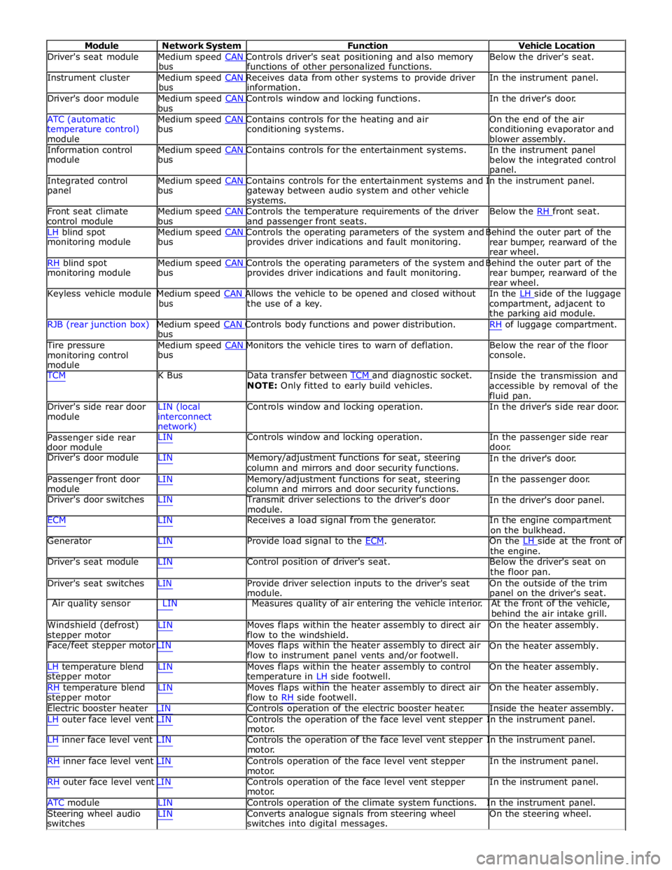
Module Network System Function Vehicle Location
Driver's seat module Medium speed CAN Controls driver's seat positioning and also memory Below the driver's seat. bus functions of other personalized functions.
Instrument cluster Medium speed CAN Receives data from other systems to provide driver In the instrument panel. bus information.
Driver's door module Medium speed CAN Controls window and locking functions. In the driver's door. bus
ATC (automatic Medium speed CAN Contains controls for the heating and air On the end of the air
temperature control)
module bus conditioning systems.
conditioning evaporator and
blower assembly.
Information control Medium speed CAN Contains controls for the entertainment systems. In the instrument panel module bus
below the integrated control
panel.
Integrated control Medium speed CAN Contains controls for the entertainment systems and In the instrument panel. panel bus
gateway between audio system and other vehicle
systems.
Front seat climate Medium speed CAN Controls the temperature requirements of the driver Below the RH front seat. control module bus and passenger front seats.
LH blind spot Medium speed CAN Controls the operating parameters of the system and Behind the outer part of the monitoring module bus provides driver indications and fault monitoring.
rear bumper, rearward of the
rear wheel.
RH blind spot Medium speed CAN Controls the operating parameters of the system and Behind the outer part of the monitoring module bus provides driver indications and fault monitoring.
rear bumper, rearward of the
rear wheel.
Keyless vehicle module Medium speed CAN Allows the vehicle to be opened and closed without In the LH side of the luggage bus the use of a key.
compartment, adjacent to
the parking aid module.
RJB (rear junction box) Medium speed CAN Controls body functions and power distribution. RH of luggage compartment. bus
Tire pressure Medium speed CAN Monitors the vehicle tires to warn of deflation. Below the rear of the floor monitoring control
module bus console.
TCM K Bus Data transfer between TCM and diagnostic socket. NOTE: Only fitted to early build vehicles. Inside the transmission and
accessible by removal of the
fluid pan.
Driver's side rear door
module LIN (local
interconnect
network) Controls window and locking operation. In the driver's side rear door.
Passenger side rear
door module LIN Controls window and locking operation. In the passenger side rear
door.
Driver's door module LIN Memory/adjustment functions for seat, steering
column and mirrors and door security functions. In the driver's door.
Passenger front door
module LIN Memory/adjustment functions for seat, steering
column and mirrors and door security functions. In the passenger door.
Driver's door switches LIN Transmit driver selections to the driver's door
module. In the driver's door panel.
ECM LIN Receives a load signal from the generator. In the engine compartment
on the bulkhead.
Generator LIN Provide load signal to the ECM. On the LH side at the front of the engine.
Driver's seat module LIN Control position of driver's seat. Below the driver's seat on
the floor pan.
Driver's seat switches LIN Provide driver selection inputs to the driver's seat
module. On the outside of the trim
panel on the driver's seat.
Air quality sensor LIN Measures quality of air entering the vehicle interior. At the front of the vehicle,
behind the air intake grill.
Windshield (defrost)
stepper motor LIN Moves flaps within the heater assembly to direct air
flow to the windshield. On the heater assembly.
Face/feet stepper motor LIN Moves flaps within the heater assembly to direct air
flow to instrument panel vents and/or footwell. On the heater assembly.
LH temperature blend
stepper motor
RH temperature blend
stepper motor LIN Moves flaps within the heater assembly to control
temperature in LH side footwell.
LIN Moves flaps within the heater assembly to direct air
flow to RH side footwell. On the heater assembly.
On the heater assembly.
Electric booster heater LIN Controls operation of the electric booster heater. Inside the heater assembly.
LH outer face level vent LIN Controls the operation of the face level vent stepper In the instrument panel.
motor.
LH inner face level vent LIN Controls the operation of the face level vent stepper In the instrument panel.
motor.
RH inner face level vent LIN Controls operation of the face level vent stepper
motor.
RH outer face level vent LIN Controls operation of the face level vent stepper
motor. In the instrument panel.
In the instrument panel.
ATC module LIN Controls operation of the climate system functions. In the instrument panel.
Steering wheel audio
switches LIN Converts analogue signals from steering wheel
switches into digital messages. On the steering wheel.
Page 2196 of 3039
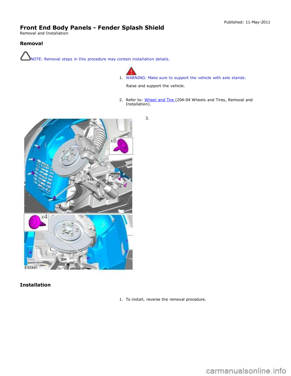
Front End Body Panels - Fender Splash Shield
Removal and Installation
Removal
NOTE: Removal steps in this procedure may contain installation details. Published: 11-May-2011
1. WARNING: Make sure to support the vehicle with axle stands.
Raise and support the vehicle.
2. Refer to: Wheel and Tire (204-04 Wheels and Tires, Removal and Installation).
3.
Installation
1. To install, reverse the removal procedure.
Page 2724 of 3039
Cooper Pegler
Burgess Hill
Sussex
RH 15 9LA
Telephone (014446) 42526
Sika Ltd
Watchmead
Welwyn Garden City
Hertfordshire
AL7 1BQ
Telephone (01707) 394444
www.sika.co.uk
SATA Spray Equipment
Minden Industrial equipment
16 Greyfriars Road
Moreton Hall
Bury St Edmunds
Suffolk
IP32 7DX
Telephone (01284) 760791
www.sata.com
Henkel Loctite Adhesives Limited
Technologies House
Wood Lane End
Hemel Hempstead
Hertfordshire
HP2 4RQ
Telephone (01442) 278000
www.loctite.co.uk
Teroson
Henkel Ltd
Apollo Court
2 Bishops Square Business Park
Hatfield
Hertfordshire
AL10 9EY
Telephone (01707) 635000
www.henkel.co.uk
Underbody sealer
Under floor areas and the front part of the spare wheel well are treated with a plastisol PVC underbody sealer. This material is
not suitable for re-treatment. When repairing areas of underbody sealer, strip the factory-applied underbody sealer back to a
suitable break point. Ensure that a clean metal surface is exposed and that the edge of the existing adheres soundly to the
panel.
Apply new underbody sealer between primer and surface paint operations. Apply seam sealer as necessary before application
of underbody sealer. Ensure that blanking plugs and grommets in the floor pan (except those used for wax injection) are fitted
before underbody sealer application. Refit any heat-fusible plugs which have been disturbed in repair with the aid of a hot air
blower, or replace with rubber grommets
CAUTION: Ensure that suspension units, wheels, tires, power unit, drive shafts, exhaust and brakes, (including all
mounting points), are shielded prior to application of fresh underbody sealer. www.JagDocs.com
Page 2846 of 3039
Ornamentation, Removal and Installation).
8. Remove the windshield glass.
For additional information, refer to: Windshield Glass (501-11 Glass, Frames and Mechanisms, Removal and Installation).
9. Remove the pedestrian protection hood actuator.
For additional information, refer to: Pedestrian Protection Hood Actuator LH (501-20C Pedestrian Protection System, Removal and Installation) / Pedestrian Protection Hood Actuator RH (501-20C Pedestrian Protection System, Removal and Installation).
10. Release and position the floor covering to one side.
11. Release and position the bulkhead insulating material to one side.
12. Release and position the inner rocker panel wiring harness to one side.
13. Remove the wheel and tire.
For additional information, refer to: Wheel and Tire (204-04 Wheels and Tires, Removal and Installation).
14. Remove the underfloor splash shield.
15. If the right-hand A-pillar outer panel is to be repaired, release and
position the underfloor wiring harness to one side.
16. Remove the front fender.
For additional information, refer to: Front Fender (501-27 Front End Sheet Metal Repairs, Removal and Installation).
17. Remove the front door.
For additional information, refer to: Front Door (501-03 Body Closures, Removal and Installation).
18. Remove the upper and lower front door hinges.
19. Remove the hood.
For additional information, refer to: Hood (501-02 Front End Body Panels, Removal and Installation).
20. Remove the hood hinge.
Page 2893 of 3039
Interior Trim and Ornamentation, Removal and Installation).
9. Remove the front safety belt retractor.
For additional information, refer to: Front Safety Belt Retractor (501-20A Safety Belt System, Removal and Installation).
10. Remove the B-pillar side impact sensor.
For additional information, refer to: B-Pillar Side Impact Sensor (501-20B Supplemental Restraint System, Removal and Installation).
11. Remove the C-pillar side impact sensor.
For additional information, refer to: C-Pillar Side Impact Sensor (501-20B Supplemental Restraint System, Removal and Installation).
12. Release and position the floor covering to one side.
13. Release and position the inner rocker panel wiring harness to one side.
14. Remove the rear wheel and tire.
For additional information, refer to: Wheel and Tire (204-04 Wheels and Tires, Removal and Installation).
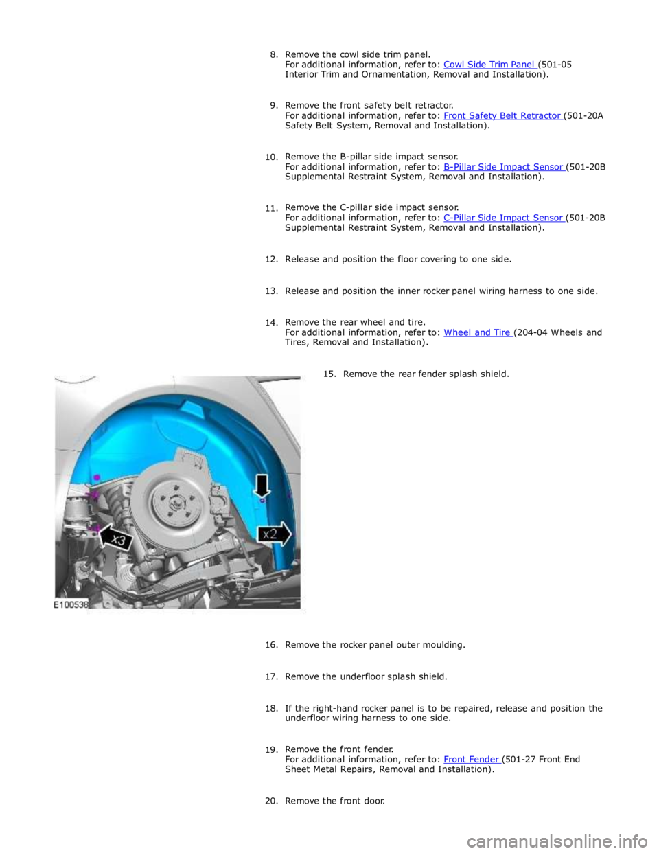
15. Remove the rear fender splash shield.
16.
Remove the rocker panel outer moulding.
17. Remove the underfloor splash shield.
18. If the right-hand rocker panel is to be repaired, release and position the
underfloor wiring harness to one side.
19. Remove the front fender.
For additional information, refer to: Front Fender (501-27 Front End Sheet Metal Repairs, Removal and Installation).
20. Remove the front door.