Page 2904 of 3039
Tires, Removal and Installation).
22. NOTE: Right-hand shown, left-hand similar.
Remove the rear fender splash shield.
23. Remove the rocker panel outer moulding.
24. Remove the underfloor splash shield.
25. If the right-hand rocker panel is to be repaired, release and position the
underfloor wiring harness to one side.
26. Remove the front door.
For additional information, refer to: Front Door (501-03 Body Closures, Removal and Installation).
27. Remove the rear door.
For additional information, refer to: Rear Door (501-03 Body Closures, Removal and Installation).
28. Remove the rear door upper and lower hinges from the B-pillar. www.JagDocs.com
Page 2932 of 3039

Interior Trim and Ornamentation, Removal and Installation).
9. Remove the front safety belt retractor.
For additional information, refer to: Front Safety Belt Retractor (501-20A Safety Belt System, Removal and Installation).
10. Remove the B-pillar side impact sensor.
For additional information, refer to: B-Pillar Side Impact Sensor (501-20B Supplemental Restraint System, Removal and Installation).
11. Remove the C-pillar side impact sensor.
For additional information, refer to: C-Pillar Side Impact Sensor (501-20B Supplemental Restraint System, Removal and Installation).
12. Release and position the floor covering to one side.
13. Release and position the inner rocker panel wiring harness to one side.
14. Remove the rear wheel and tire.
For additional information, refer to: Wheel and Tire (204-04 Wheels and Tires, Removal and Installation).
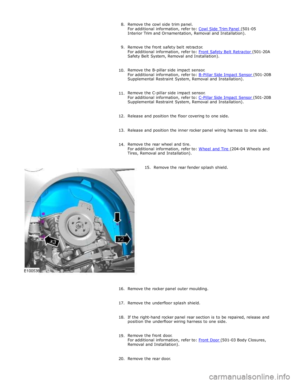
15. Remove the rear fender splash shield.
16.
Remove the rocker panel outer moulding.
17. Remove the underfloor splash shield.
18. If the right-hand rocker panel rear section is to be repaired, release and
position the underfloor wiring harness to one side.
19. Remove the front door.
For additional information, refer to: Front Door (501-03 Body Closures, Removal and Installation).
20. Remove the rear door.
Page 2948 of 3039
(100-00 General Information, Description and Operation) /
Body Repairs (501-25A Body Repairs - General Information, Description and Operation) /
Corrosion Protection (501-25B Body Repairs - Corrosion Protection, Description and Operation) /
Body and Frame (501-26 Body Repairs - Vehicle Specific Information and Tolerance Checks, Description and Operation).
4. Remove the rear wheel and tire.
For additional information, refer to: Wheel and Tire (204-04 Wheels and Tires, Removal and Installation).
5. Remove the rear fender splash shield.
Page 2961 of 3039
11. Release and lay aside the back panel and loadspace wiring harness.
12. Remove the rear bumper cover side retainer.
13. Remove the rear wheel and tire.
For additional information, refer to: Wheel and Tire (204-04 Wheels and Tires, Removal and Installation).
14.
15. Remove the rear fender splash shield.
NOTE: Where applicable spot welds must be drilled
from the inside, this will enable the new panel to be spot
welded on installation. Use a belt sander where there is no
access to drill.
Drill out the spot welds.
Page 3032 of 3039

Published: 11-May-2011
Uni-Body, Subframe and Mounting System - Rear Subframe V8 5.0L Petrol/V8 S/C 5.0L Petrol
Removal and Installation
General Equipment
Removal
NOTE: Removal steps in this procedure may contain installation details.
1. Refer to: Petrol and Petrol-Ethanol Fuel Systems Health and Safety Precautions (100-00 General Information, Description and Operation).
2. WARNING: Do not work on or under a vehicle supported only by a jack.
Always support the vehicle on safety stands.
Raise and support the vehicle.
3. Refer to: Fuel Tank Draining (310-00 Fuel System - General Information, General Procedures).
4. Refer to: Wheel and Tire (204-04 Wheels and Tires, Removal and Installation).
5. Refer to: Driveshaft - V8 5.0L Petrol/V8 S/C 5.0L Petrol (205-01 Driveshaft, Removal and Installation).
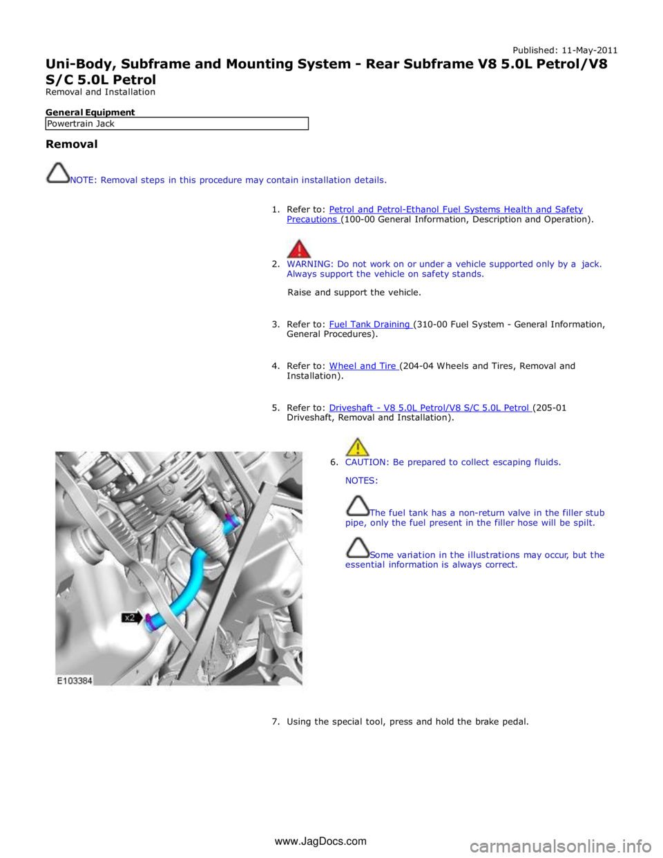
6. CAUTION: Be prepared to collect escaping fluids.
NOTES:
The fuel tank has a non-return valve in the filler stub
pipe, only the fuel present in the filler hose will be spilt.
Some variation in the illustrations may occur, but the
essential information is always correct.
7. Using the special tool, press and hold the brake pedal. Powertrain Jack www.JagDocs.com