2010 JAGUAR XFR Can bus
[x] Cancel search: Can busPage 1530 of 3039
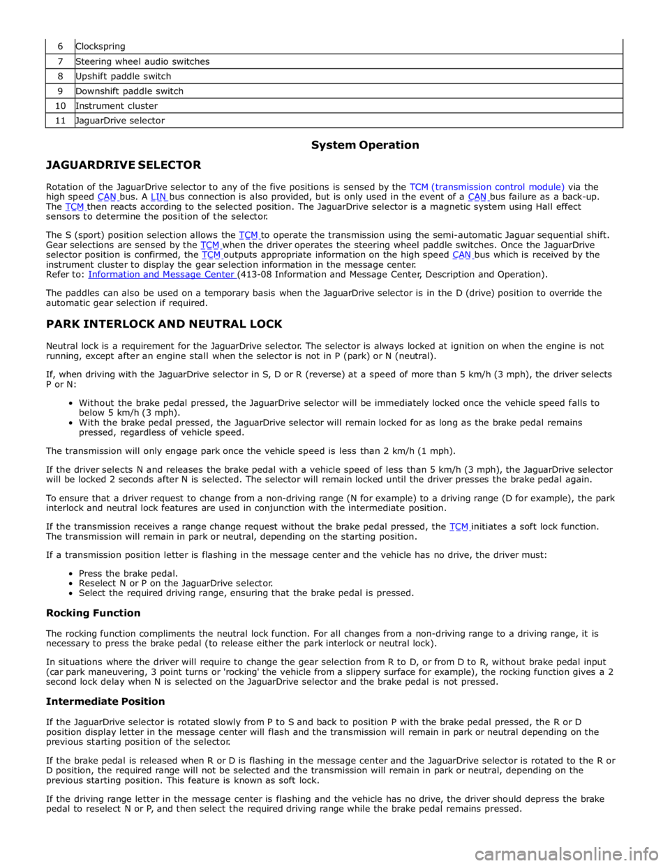
6 Clockspring 7 Steering wheel audio switches 8 Upshift paddle switch 9 Downshift paddle switch 10 Instrument cluster 11 JaguarDrive selector
JAGUARDRIVE SELECTOR System Operation
Rotation of the JaguarDrive selector to any of the five positions is sensed by the TCM (transmission control module) via the
high speed CAN bus. A LIN bus connection is also provided, but is only used in the event of a CAN bus failure as a back-up. The TCM then reacts according to the selected position. The JaguarDrive selector is a magnetic system using Hall effect sensors to determine the position of the selector.
The S (sport) position selection allows the TCM to operate the transmission using the semi-automatic Jaguar sequential shift. Gear selections are sensed by the TCM when the driver operates the steering wheel paddle switches. Once the JaguarDrive selector position is confirmed, the TCM outputs appropriate information on the high speed CAN bus which is received by the instrument cluster to display the gear selection information in the message center.
Refer to: Information and Message Center (413-08 Information and Message Center, Description and Operation).
The paddles can also be used on a temporary basis when the JaguarDrive selector is in the D (drive) position to override the
automatic gear selection if required.
PARK INTERLOCK AND NEUTRAL LOCK
Neutral lock is a requirement for the JaguarDrive selector. The selector is always locked at ignition on when the engine is not
running, except after an engine stall when the selector is not in P (park) or N (neutral).
If, when driving with the JaguarDrive selector in S, D or R (reverse) at a speed of more than 5 km/h (3 mph), the driver selects
P or N:
Without the brake pedal pressed, the JaguarDrive selector will be immediately locked once the vehicle speed falls to
below 5 km/h (3 mph).
With the brake pedal pressed, the JaguarDrive selector will remain locked for as long as the brake pedal remains
pressed, regardless of vehicle speed.
The transmission will only engage park once the vehicle speed is less than 2 km/h (1 mph).
If the driver selects N and releases the brake pedal with a vehicle speed of less than 5 km/h (3 mph), the JaguarDrive selector
will be locked 2 seconds after N is selected. The selector will remain locked until the driver presses the brake pedal again.
To ensure that a driver request to change from a non-driving range (N for example) to a driving range (D for example), the park
interlock and neutral lock features are used in conjunction with the intermediate position.
If the transmission receives a range change request without the brake pedal pressed, the TCM initiates a soft lock function. The transmission will remain in park or neutral, depending on the starting position.
If a transmission position letter is flashing in the message center and the vehicle has no drive, the driver must:
Press the brake pedal.
Reselect N or P on the JaguarDrive selector.
Select the required driving range, ensuring that the brake pedal is pressed.
Rocking Function
The rocking function compliments the neutral lock function. For all changes from a non-driving range to a driving range, it is
necessary to press the brake pedal (to release either the park interlock or neutral lock).
In situations where the driver will require to change the gear selection from R to D, or from D to R, without brake pedal input
(car park maneuvering, 3 point turns or 'rocking' the vehicle from a slippery surface for example), the rocking function gives a 2
second lock delay when N is selected on the JaguarDrive selector and the brake pedal is not pressed.
Intermediate Position
If the JaguarDrive selector is rotated slowly from P to S and back to position P with the brake pedal pressed, the R or D
position display letter in the message center will flash and the transmission will remain in park or neutral depending on the
previous starting position of the selector.
If the brake pedal is released when R or D is flashing in the message center and the JaguarDrive selector is rotated to the R or
D position, the required range will not be selected and the transmission will remain in park or neutral, depending on the
previous starting position. This feature is known as soft lock.
If the driving range letter in the message center is flashing and the vehicle has no drive, the driver should depress the brake
pedal to reselect N or P, and then select the required driving range while the brake pedal remains pressed.
Page 1532 of 3039
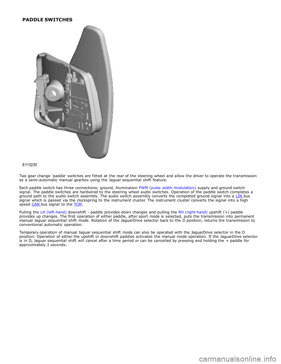
signal which is passed via the clockspring to the instrument cluster. The instrument cluster converts the signal into a high
speed CAN bus signal to the TCM.
Pulling the LH (left-hand) downshift - paddle provides down changes and pulling the RH (right-hand) upshift (+) paddle
provides up changes. The first operation of either paddle, after sport mode is selected, puts the transmission into permanent
manual Jaguar sequential shift mode. Rotation of the JaguarDrive selector back to the D position, returns the transmission to
conventional automatic operation.
Temporary operation of manual Jaguar sequential shift mode can also be operated with the JaguarDrive selector in the D
position. Operation of either the upshift or downshift paddles activates the manual mode operation. If the JaguarDrive selector
is in D, Jaguar sequential shift will cancel after a time period or can be cancelled by pressing and holding the + paddle for
approximately 2 seconds. PADDLE SWITCHES
Page 1640 of 3039
Published: 29-Sep-2011
Speed Control - V8 5.0L Petrol/V8 S/C 5.0L Petrol - Speed Control - System
Operation and Component Description
Description and Operation
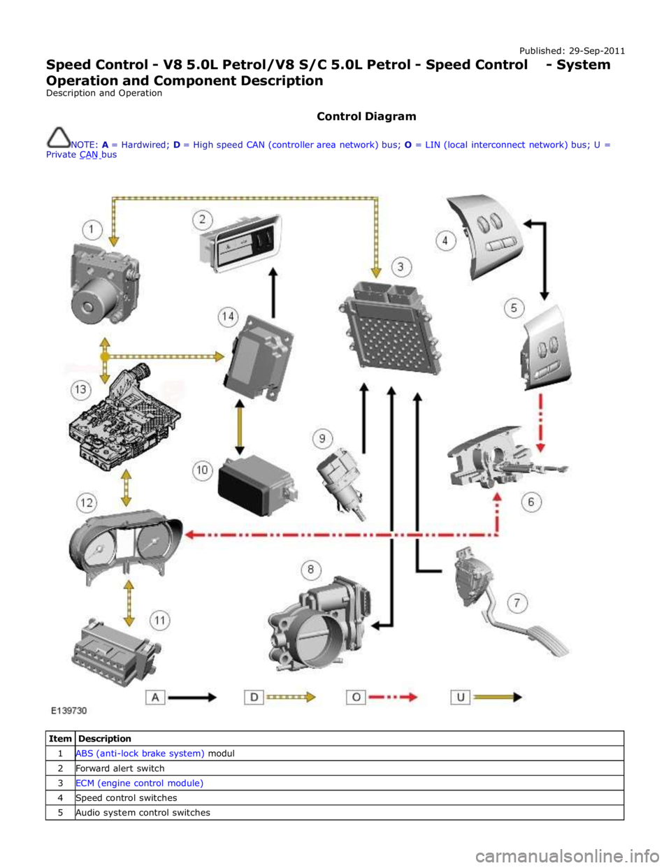
Control Diagram
NOTE: A = Hardwired; D = High speed CAN (controller area network) bus; O = LIN (local interconnect network) bus; U =
Private CAN bus
Item Description 1 ABS (anti-lock brake system) modul 2 Forward alert switch 3 ECM (engine control module) 4 Speed control switches 5 Audio system control switches
Page 1644 of 3039
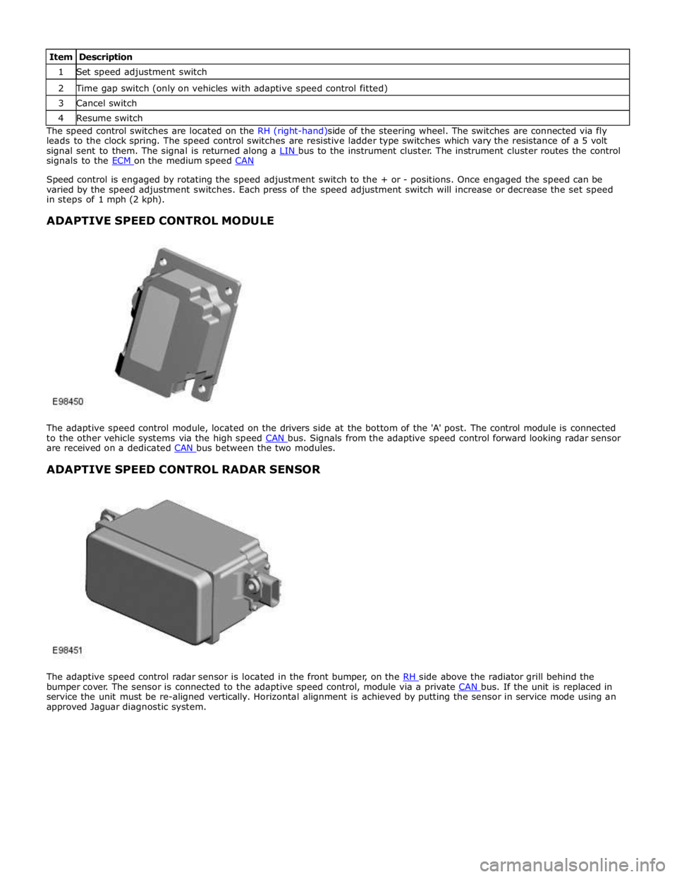
1 Set speed adjustment switch 2 Time gap switch (only on vehicles with adaptive speed control fitted) 3 Cancel switch 4 Resume switch The speed control switches are located on the RH (right-hand)side of the steering wheel. The switches are connected via fly
leads to the clock spring. The speed control switches are resistive ladder type switches which vary the resistance of a 5 volt
signal sent to them. The signal is returned along a LIN bus to the instrument cluster. The instrument cluster routes the control signals to the ECM on the medium speed CAN
Speed control is engaged by rotating the speed adjustment switch to the + or - positions. Once engaged the speed can be
varied by the speed adjustment switches. Each press of the speed adjustment switch will increase or decrease the set speed
in steps of 1 mph (2 kph).
ADAPTIVE SPEED CONTROL MODULE
The adaptive speed control module, located on the drivers side at the bottom of the 'A' post. The control module is connected
to the other vehicle systems via the high speed CAN bus. Signals from the adaptive speed control forward looking radar sensor are received on a dedicated CAN bus between the two modules.
ADAPTIVE SPEED CONTROL RADAR SENSOR
The adaptive speed control radar sensor is located in the front bumper, on the RH side above the radiator grill behind the bumper cover. The sensor is connected to the adaptive speed control, module via a private CAN bus. If the unit is replaced in service the unit must be re-aligned vertically. Horizontal alignment is achieved by putting the sensor in service mode using an
approved Jaguar diagnostic system.
Page 1645 of 3039
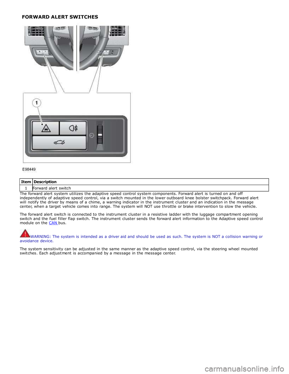
Item Description 1 Forward alert switch The forward alert system utilizes the adaptive speed control system components. Forward alert is turned on and off
independently of adaptive speed control, via a switch mounted in the lower outboard knee bolster switchpack. Forward alert
will notify the driver by means of a chime, a warning indicator in the instrument cluster and an indication in the message
center, when a target vehicle comes into range. The system will NOT use throttle or brake intervention to slow the vehicle.
The forward alert switch is connected to the instrument cluster in a resistive ladder with the luggage compartment opening
switch and the fuel filler flap switch. The instrument cluster sends the forward alert information to the Adaptive speed control
module on the CAN bus.
WARNING: The system is intended as a driver aid and should be used as such. The system is NOT a collision warning or
avoidance device.
The system sensitivity can be adjusted in the same manner as the adaptive speed control, via the steering wheel mounted
switches. Each adjustment is accompanied by a message in the message center. FORWARD ALERT SWITCHES
Page 1648 of 3039

DTC Description Possible Causes Action C1A67-98 Forward Looking Sensor
- Component or system
over temperature
Speed control sensor
internal temperature
exceeded threshold
Allow system to cool. Note: This DTC will be cleared
automatically when environmental conditions allow P174E-81
Output Shaft
Speed/ABS Wheel
Speed Correlation -
Invalid serial data
received
Follow speed is
mis-calculated to too
high a value
Clear DTC and re-test U0001-88
High Speed CAN
Communication Bus -
Bus off
Vehicle CAN Bus off
condition
Carry out any pinpoint tests associated with this
DTC using the manufacturer approved diagnostic
system. Carry out CAN network integrity tests using
the manufacturer approved diagnostic system U0100-00
Lost Communications
With ECM/PCM "A" - No
sub type information
ECM missing message
Carry out any pinpoint tests associated with this
DTC using the manufacturer approved diagnostic
system. Check ECM for related DTCs and refer to the
relevant DTC Index U0101-00
Lost Communications
With TCM - No sub
type information
TCM missing message
Carry out any pinpoint tests associated with this
DTC using the manufacturer approved diagnostic
system. Check TCM for related DTCs and refer to the
relevant DTC Index U0103-00
Lost Communication
With Gear Shift Control
Module A - No sub type
information
No sub type information
Refer to the electrical circuit diagrams and check the
power and ground connections to the Transmission
Shift Module. Using the manufacturer approved
diagnostic system, complete a CAN network integrity
test. Refer to the electrical circuit diagrams and
check the CAN network between the Transmission
Shift Module and Speed Control Module U0103-87
Lost Communication
With Gear Shift Module
- Missing Message
Transmission shift
module missing message
Carry out any pinpoint tests associated with this
DTC using the manufacturer approved diagnostic
system. Check transmission shift module for related
DTCs and refer to the relevant DTC Index U0121-00
Lost Communication
With Anti-lock Brake
System (ABS) Control
Module - No sub type
information
ABS missing message
Carry out any pinpoint tests associated with this
DTC using the manufacturer approved diagnostic
system. Check ABS for related DTCs and refer to the
relevant DTC Index U0128-00
Lost Communications
With Park Brake Module
- No sub type
information
Parking brake missing
message
Carry out any pinpoint tests associated with this
DTC using the manufacturer approved diagnostic
system. Check parking brake module for related
DTCs and refer to the relevant DTC Index U0155-00
Lost Communications
With Instrument Panel
Cluster (IPC) Control
Module - No sub type
information
Instrument cluster
missing message
Carry out any pinpoint tests associated with this
DTC using the manufacturer approved diagnostic
system. Check instrument cluster for related DTCs
and refer to the relevant DTC Index U0300-00
Internal Control Module
Software
Incompatibility - No
sub type information
Invalid configuration
message is received
Re-configure the speed control module using the
manufacturer approved diagnostic system. Clear
DTCs and re-test. If DTC still logged, suspect
incorrect speed control module installed. Check and
install a new module as required, refer to new
module/component installation note at top of DTC
Index U0300-55
Internal Control Module
Software
Incompatibility - Not
configured
RJB - at least one of the
car configuration
parameters is not
configured
Re-configure the RJB using the manufacturer
approved diagnostic system www.JagDocs.com
Page 1649 of 3039

DTC Description Possible Causes Action U0401-00
Invalid Data Received
From ECM/PCM A - No
sub type information
ECM did not respond
properly to speed control
cancel or auto brake
cancel request
Check ECM for related DTCs and refer to relevant
DTC Index U0401-67
Invalid Data Received
From ECM/PCM A -
Signal incorrect after
event
ECM did not respond
properly to speed control
resume request
Check ECM for related DTCs and refer to relevant
DTC Index U0401-81
Invalid Data Received
From ECM/PCM A -
Invalid serial data
received
Invalid data received
from engine control
module
Bus signal/message
failure
Speed control inhibited
by ECM
Check the Engine Control Module for related DTCs
and refer to relevant DTC Index. If U040181 is
logged as historic but no other DTCs have logged in
the engine control module at the same time and
distance, it may be caused by cranking with low
voltage conditions. Check battery and charging
system according to instructions in the battery care
manual. Install the latest Engine Control Module
software using the manufacturer approved diagnostic
system, contact Dealer Technical Support before
replacing components U0415-53
Invalid Data Received
From Anti-Lock Braking
System (ABS) Control
Module - De-activated
Event information
Deactivated
Check the Anti-Lock Braking System Module for
related DTCs and refer to the relevant DTC index U0415-81
Invalid Data Received
From Anti-lock Brake
System (ABS) Control
Module - Invalid serial
data received
Stability assist fault
Check ABS module for related DTCs and refer to
relevant DTC Index U0417-67
Invalid Data Received
From Park Brake
Control Module - Signal
incorrect after event
Parking brake module did
not respond properly to
apply request
Check parking brake module for related DTCs and
refer to relevant DTC Index U0417-81
Invalid Data Received
From Park Brake
Control Module -
Invalid serial data
received
Speed control inhibited
by parking brake module
Check parking brake module for related DTCs and
refer to relevant DTC Index U0418-68
Invalid Data Received
From Brake System
Control Module - Event
information
Event information
Check the Anti-Lock Braking System Module for
related DTCs and refer to the relevant DTC index U0421-81
Invalid Data Received
From Suspension
Control Module 'A' -
Invalid serial data
received
Invalid serial data
received
Check the Suspension Control Module for related
DTCs and refer to the relevant DTC index U0423-81
Invalid Data Received
From Instrument Panel
Control Module -
Invalid serial data
received
Speed control inhibited
by instrument cluster
Check instrument cluster, CJB and RJB for related
DTCs and refer to relevant DTC Index U1A00-88
Private Communication
Network - Bus off
Bus off
The module setting this code has disabled CAN
transmission. Check for other bus off codes. Check
the module and circuits. Refer to the electrical circuit
diagrams. Clear all DTCs and road test the vehicle. If
the concern reoccurs contact Dealer Technical
Support for further advice. Under no circumstance
should any parts be replaced to overcome this issue U1A14-49
CAN Initialisation
Failure - Internal
electronic failure
Internal electronic failure
Suspect the speed control module. Check and install
a new module as required, refer to the new
module/component installation note at the top of
the DTC Index U2101-00
Control Module
Configuration
Incompatible - No sub
type information
Data sent from RJB is
invalid
Check/amend Car Configuration File using the
manufacturer approved diagnostic system, clear DTC
and re-test. If DTC remains, re-configure RJB using
manufacturer approved diagnostic system, clear DTC
and re-test. If DTC remains check RJB for DTCs and
Page 1686 of 3039
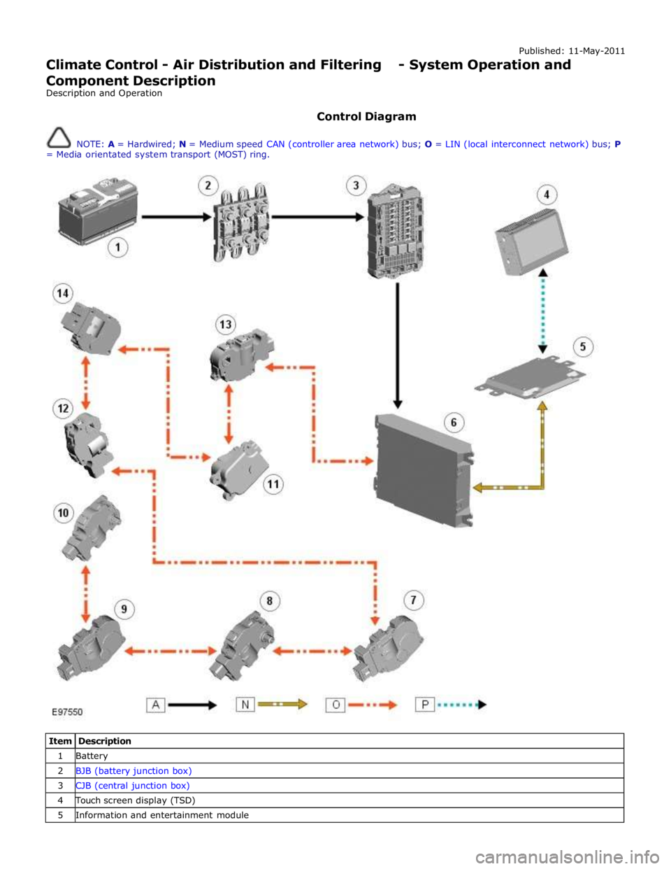
Published: 11-May-2011
Climate Control - Air Distribution and Filtering - System Operation and
Component Description
Description and Operation
Control Diagram
NOTE: A = Hardwired; N = Medium speed CAN (controller area network) bus; O = LIN (local interconnect network) bus; P
= Media orientated system transport (MOST) ring.
Item Description 1 Battery 2 BJB (battery junction box) 3 CJB (central junction box) 4 Touch screen display (TSD) 5 Information and entertainment module