2010 JAGUAR XFR Can bus
[x] Cancel search: Can busPage 798 of 3039
Published: 11-May-2011
Steering Column Switches - Steering Column Switches - System Operation
and Component Description
Description and Operation
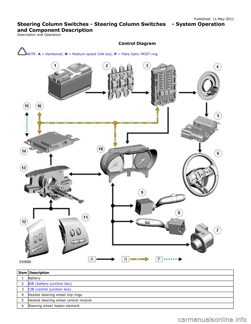
Control Diagram
NOTE: A = Hardwired; N = Medium speed CAN bus; P = Fibre Optic MOST ring
Item Description 1 Battery 2 BJB (battery junction box) 3 CJB (central junction box) 4 Heated steering wheel slip rings 5 Heated steering wheel control module 6 Steering wheel heater element
Page 799 of 3039
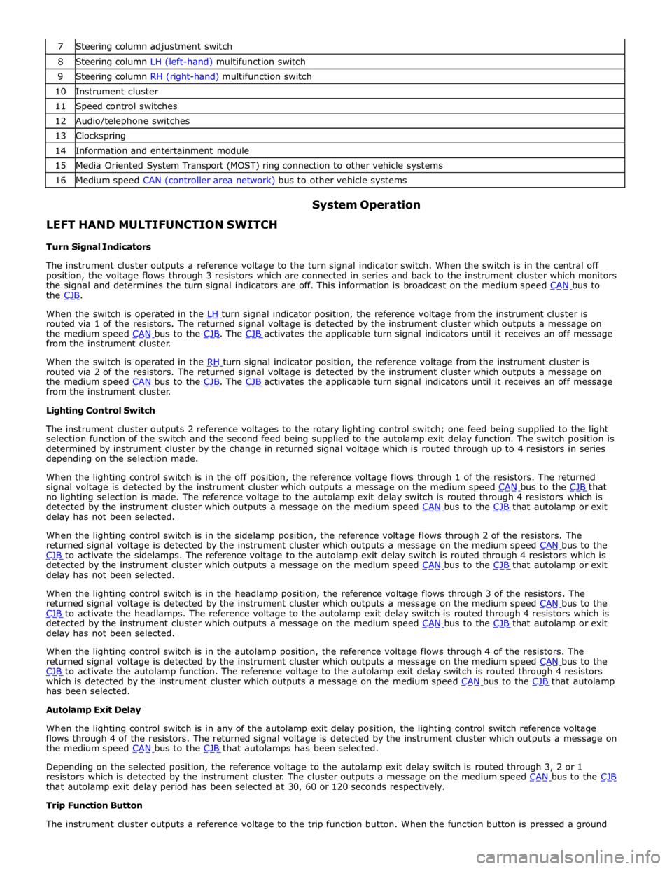
8 Steering column LH (left-hand) multifunction switch 9 Steering column RH (right-hand) multifunction switch 10 Instrument cluster 11 Speed control switches 12 Audio/telephone switches 13 Clockspring 14 Information and entertainment module 15 Media Oriented System Transport (MOST) ring connection to other vehicle systems 16 Medium speed CAN (controller area network) bus to other vehicle systems
LEFT HAND MULTIFUNCTION SWITCH
Turn Signal Indicators System Operation
The instrument cluster outputs a reference voltage to the turn signal indicator switch. When the switch is in the central off
position, the voltage flows through 3 resistors which are connected in series and back to the instrument cluster which monitors
the signal and determines the turn signal indicators are off. This information is broadcast on the medium speed CAN bus to the CJB.
When the switch is operated in the LH turn signal indicator position, the reference voltage from the instrument cluster is routed via 1 of the resistors. The returned signal voltage is detected by the instrument cluster which outputs a message on
the medium speed CAN bus to the CJB. The CJB activates the applicable turn signal indicators until it receives an off message from the instrument cluster.
When the switch is operated in the RH turn signal indicator position, the reference voltage from the instrument cluster is routed via 2 of the resistors. The returned signal voltage is detected by the instrument cluster which outputs a message on
the medium speed CAN bus to the CJB. The CJB activates the applicable turn signal indicators until it receives an off message from the instrument cluster.
Lighting Control Switch
The instrument cluster outputs 2 reference voltages to the rotary lighting control switch; one feed being supplied to the light
selection function of the switch and the second feed being supplied to the autolamp exit delay function. The switch position is
determined by instrument cluster by the change in returned signal voltage which is routed through up to 4 resistors in series
depending on the selection made.
When the lighting control switch is in the off position, the reference voltage flows through 1 of the resistors. The returned
signal voltage is detected by the instrument cluster which outputs a message on the medium speed CAN bus to the CJB that no lighting selection is made. The reference voltage to the autolamp exit delay switch is routed through 4 resistors which is
detected by the instrument cluster which outputs a message on the medium speed CAN bus to the CJB that autolamp or exit delay has not been selected.
When the lighting control switch is in the sidelamp position, the reference voltage flows through 2 of the resistors. The
returned signal voltage is detected by the instrument cluster which outputs a message on the medium speed CAN bus to the CJB to activate the sidelamps. The reference voltage to the autolamp exit delay switch is routed through 4 resistors which is detected by the instrument cluster which outputs a message on the medium speed CAN bus to the CJB that autolamp or exit delay has not been selected.
When the lighting control switch is in the headlamp position, the reference voltage flows through 3 of the resistors. The
returned signal voltage is detected by the instrument cluster which outputs a message on the medium speed CAN bus to the CJB to activate the headlamps. The reference voltage to the autolamp exit delay switch is routed through 4 resistors which is detected by the instrument cluster which outputs a message on the medium speed CAN bus to the CJB that autolamp or exit delay has not been selected.
When the lighting control switch is in the autolamp position, the reference voltage flows through 4 of the resistors. The
returned signal voltage is detected by the instrument cluster which outputs a message on the medium speed CAN bus to the CJB to activate the autolamp function. The reference voltage to the autolamp exit delay switch is routed through 4 resistors which is detected by the instrument cluster which outputs a message on the medium speed CAN bus to the CJB that autolamp has been selected.
Autolamp Exit Delay
When the lighting control switch is in any of the autolamp exit delay position, the lighting control switch reference voltage
flows through 4 of the resistors. The returned signal voltage is detected by the instrument cluster which outputs a message on
the medium speed CAN bus to the CJB that autolamps has been selected.
Depending on the selected position, the reference voltage to the autolamp exit delay switch is routed through 3, 2 or 1
resistors which is detected by the instrument cluster. The cluster outputs a message on the medium speed CAN bus to the CJB that autolamp exit delay period has been selected at 30, 60 or 120 seconds respectively.
Trip Function Button
The instrument cluster outputs a reference voltage to the trip function button. When the function button is pressed a ground
Page 800 of 3039
path is completed and a signal voltage is returned to the instrument cluster via a resistor. The returned reference voltage is
detected by the instrument cluster and performs the requested trip function.
RIGHT HAND MULTIFUNCTION SWITCH
The instrument cluster outputs 4 separate reference voltages to the following switch functions:
Wash/wipe switch
Intermittent wipe switch
Master wiper switch
Flick wipe switch.
Wash/Wipe Switch
The reference voltage is supplied to one of two resistors connected in parallel. When the switch is not being operated the
current flows through one resistor and the returned signal voltage is monitored by the instrument cluster. When the wash/wipe
switch is operated, a connection is made and the current flows through the second resistor. The change in signal voltage is
detected by the instrument cluster which outputs a message on the medium speed CAN bus to the CJB to activate the wash/wipe function.
Intermittent Delay/Auto Wipe Switch
The reference voltage is supplied to the switch and can pass through up to 7 resistors, connected in series, for intermittent
delay selections and the auto wipe function.
When the rotary switch is in the auto position the reference voltage flows through 1 resistor. The returned signal voltage is
detected by the instrument cluster which determines auto wipe is selected. The instrument cluster outputs a message on the
medium speed CAN bus to the CJB to activate the auto wipe function.
With the rotary switch in one of the intermittent positions, the reference voltage is routed through up to 7 of the resistors
depending on the delay period selected. The returned signal voltage is detected by the instrument cluster which determines
selected delay period. The instrument cluster outputs a message on the medium speed CAN bus to the CJB to activate the selected intermittent wipe function.
NOTE: The delay period for the intermittent selections can vary according to vehicle speed.
Master Wiper Switch
The reference voltage supplied from the instrument cluster to the master wiper switch. The voltage can pass through up to 4
resistors connected in series.
When the switch is in the off position, the reference voltage passes through 4 resistors and the returned voltage is monitored
by the instrument cluster. The instrument cluster outputs a message on the medium speed CAN bus to the CJB that no wiper selections have been requested.
With the switch in the intermittent, slow wipe or fast wipe position, the reference voltage passes through 3, 2 or 1 resistors
respectively. The returned signal voltage is detected by the instrument cluster which determines selected delay period. The
instrument cluster outputs a message on the medium speed CAN bus to the CJB to activate the selected wipe function. Flick Wipe Switch
The reference voltage is supplied to one of two resistors connected in parallel. When the switch is not being operated the
current flows through one resistor and the returned signal voltage is monitored by the instrument cluster. When the flick wipe
switch is operated, a connection is made and the current flows through the second resistor. The change in signal voltage is
detected by the instrument cluster which outputs a message on the medium speed CAN bus to the CJB to activate the flick wipe function.
STEERING COLUMN ADJUSTMENT SWITCH
The instrument cluster supplies 2 reference voltages to the column adjustment switch.
The first reference voltage is supplied to the joystick switch. When the switch is moved to one of its 4 positions, the switch
contact is completed and the reference voltage is passed through one of 4 different resistors with different values. The
returned signal voltage is measured by the instrument cluster which determines the selected column adjust request. The
instrument cluster outputs a supply to the steering column adjustment motor and energizes the applicable clutch solenoid to
move the column to the desired position.
The second reference voltage is supplied to the auto/manual selection of the switch. When the switch is in the auto position,
the reference voltage passes directly through the switch contacts and is measured by the instrument cluster. The instrument
cluster outputs a message on the medium speed CAN bus to the driver seat module which responds with the recorded memory position setting. The instrument cluster then activates the column adjustment motor and clutch solenoids to move the column
to the memorized position. When the switch is in the manual position the reference circuit is broken. The instrument cluster
detects the broken circuit and allows manual operation of the column adjustment switch to move the column.
HEATED STEERING WHEEL
The heated steering wheel receives a battery power supply via the CJB. The heated steering wheel is controlled by the driver using a selection on the TSD. When the driver selects the heated steering wheel to be active, the request is passed from the
TSD on the MOST ring to the information and entertainment module. The information and entertainment module converts the
Page 814 of 3039
engine oil).
Oil Consumption Test
The amount of oil an engine uses will vary with the way the vehicle is driven in addition to normal engine-to-engine variation.
This is especially true during the first 16,100 km (10,000 miles) when a new engine is being broken in or until certain internal
components become conditioned. Vehicles used in heavy-duty operation may use more oil. The following are examples of
heavy-duty operation:
Trailer towing applications
Severe loading applications
Sustained high speed operation
Engines need oil to lubricate the following internal components:
Cylinder block cylinder walls
Pistons and piston rings
Intake and exhaust valve stems
Intake and exhaust valve guides
All internal engine components
When the pistons move downward, a thin film of oil is left on the cylinder walls. As the vehicle is operated, some oil is also
drawn into the combustion chambers past the intake and exhaust valve stem seals and burned.
The following are examples of conditions that can affect oil consumption rates:
Engine size
Operator driving habits
Ambient temperatures
Quality and viscosity of oil
Engine is being run in an overfilled condition (check the oil level at least five minutes after a hot shutdown with the
vehicle parked on a level surface. The oil level should not be above the top of the cross-hatched area and the letter "F"
in FULL).
Operation under varying conditions can frequently be misleading. A vehicle that has been run for several thousand miles on
short trips or in below-freezing ambient temperatures may have consumed a "normal" amount of oil. However, when checking
the engine oil level, it may measure up to the full mark on the oil level indicator due to dilution (condensation and fuel) in the
engine crankcase. The vehicle then might be driven at high speeds on the highway where the condensation and fuel boil off.
The next time the engine oil is checked it may appear that a liter of oil was used in about 160 km (100 miles). Oil
consumption rate is about one liter per 2,400 km (1,500 miles).
Make sure the selected engine oil meets Jaguar specification and the recommended API performance category "SG" and SAE
viscosity grade as shown in the vehicle Owner's Guide. It is also important that the engine oil is changed at the intervals
specified for the typical operating conditions.
The following diagnostic procedure is used to determine the source of excessive oil consumption.
NOTE: Oil use is normally greater during the first 16,100 km (10,000 miles) of service. As mileage increases, oil use
decreases. High speed driving, towing, high ambient temperature and other factors may result in greater oil use.
1. Define excessive consumption, such as the number of miles driven per liter of oil used. Also determine customers
driving habits, such as sustained high speed operation, towing, extended idle and other considerations.
2. Verify that the engine has no external oil leaks as described under Engine Oil Leaks in this section.
3. Carry out an oil consumption test:
Run the engine to normal operating temperature. Switch engine OFF and allow oil to drain back for at least five
minutes .
With vehicle parked on level surface, check the engine oil level.
If required, add engine oil to set level exactly to the FULL mark.
Record the vehicle mileage.
Instruct the customer to return for a level check after driving the vehicle as usual for 1,610 km (1000 miles).
Check the oil level under the same conditions and at the same location as the initial check.
NOTE: If the oil consumption rate is unacceptable go to Step 4.
4. Check the Positive Crankcase Ventilation (PCV) system. Make sure the system is not plugged.
5. Check for plugged oil drain-back holes in the cylinder head and cylinder block.
6. If the condition still exists after carrying out the above tests go to step 9.
7. Carry out a cylinder compression test. Refer to the Compression Test procedure in this section. This can help determine
the source of oil consumption such as valves, piston rings or other areas.
8. Check valve guides for excessive guide clearance. Install new valve stem seals after verifying valve guide clearance.
9. Worn or damaged internal engine components can cause excessive oil consumption. Small deposits of oil on the tips of
the spark plugs can be a clue to internal oil consumption.
Page 1358 of 3039
Published: 11-May-2011
Electronic Engine Controls - V8 S/C 5.0L Petrol - Electronic Engine Controls - System Operation and Component Description
Description and Operation
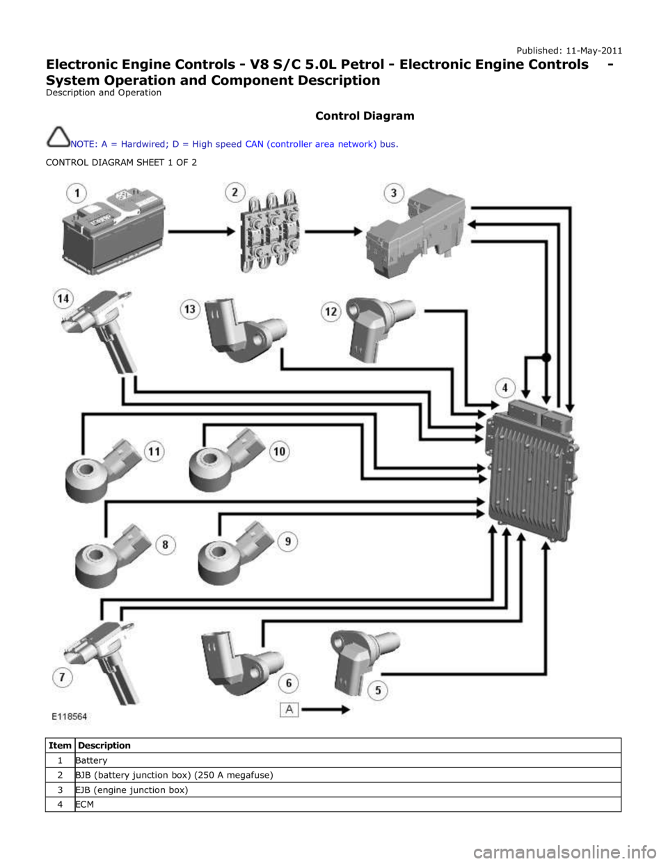
Control Diagram
NOTE: A = Hardwired; D = High speed CAN (controller area network) bus.
CONTROL DIAGRAM SHEET 1 OF 2
Item Description 1 Battery 2 BJB (battery junction box) (250 A megafuse) 3 EJB (engine junction box) 4 ECM
Page 1367 of 3039
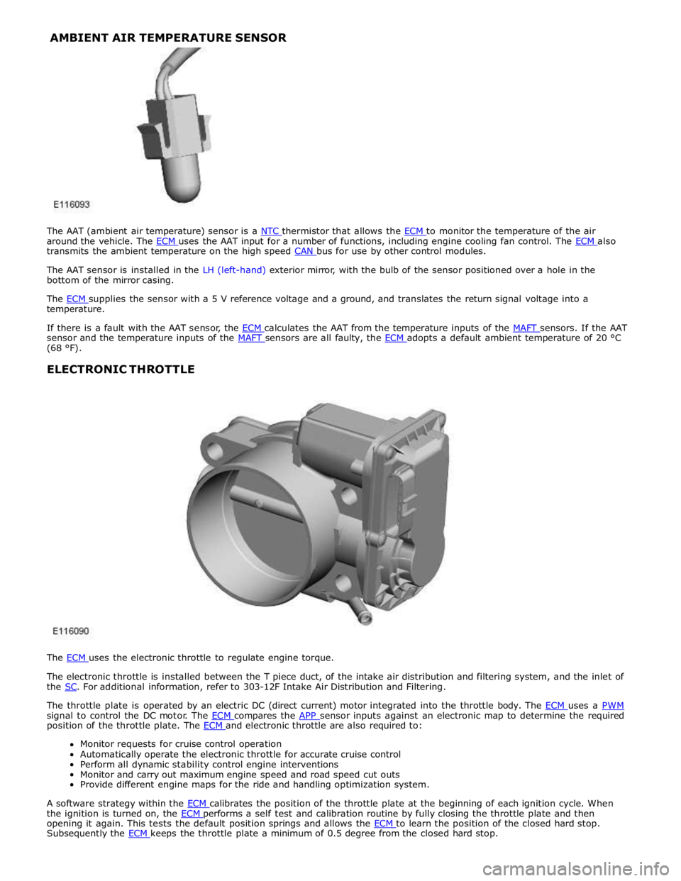
around the vehicle. The ECM uses the AAT input for a number of functions, including engine cooling fan control. The ECM also transmits the ambient temperature on the high speed CAN bus for use by other control modules.
The AAT sensor is installed in the LH (left-hand) exterior mirror, with the bulb of the sensor positioned over a hole in the
bottom of the mirror casing.
The ECM supplies the sensor with a 5 V reference voltage and a ground, and translates the return signal voltage into a temperature.
If there is a fault with the AAT sensor, the ECM calculates the AAT from the temperature inputs of the MAFT sensors. If the AAT sensor and the temperature inputs of the MAFT sensors are all faulty, the ECM adopts a default ambient temperature of 20 °C (68 °F).
ELECTRONIC THROTTLE
The ECM uses the electronic throttle to regulate engine torque.
The electronic throttle is installed between the T piece duct, of the intake air distribution and filtering system, and the inlet of
the SC. For additional information, refer to 303-12F Intake Air Distribution and Filtering.
The throttle plate is operated by an electric DC (direct current) motor integrated into the throttle body. The ECM uses a PWM signal to control the DC motor. The ECM compares the APP sensor inputs against an electronic map to determine the required position of the throttle plate. The ECM and electronic throttle are also required to: Monitor requests for cruise control operation
Automatically operate the electronic throttle for accurate cruise control
Perform all dynamic stability control engine interventions
Monitor and carry out maximum engine speed and road speed cut outs
Provide different engine maps for the ride and handling optimization system.
A software strategy within the ECM calibrates the position of the throttle plate at the beginning of each ignition cycle. When the ignition is turned on, the ECM performs a self test and calibration routine by fully closing the throttle plate and then opening it again. This tests the default position springs and allows the ECM to learn the position of the closed hard stop. Subsequently the ECM keeps the throttle plate a minimum of 0.5 degree from the closed hard stop. AMBIENT AIR TEMPERATURE SENSOR
Page 1410 of 3039
Published: 11-May-2011
Automatic Transmission/Transaxle - TDV6 3.0L Diesel /V8 5.0L Petrol/V8 S/C 5.0L Petrol - Transmission Description - Overview
Description and Operation
OVERVIEW
The ZF 6HP28 transmission is an electronically controlled, hydraulically operated, six speed automatic unit. The hydraulic and
electronic control elements of the transmission, including the TCM (transmission control module), are incorporated in a single
unit located inside the transmission and is known as 'Mechatronic'.
5.1 L SC (supercharger) and 3.0L diesel models use an uprated derivative of the ZF 6HP28 transmission used in the 5.0L
naturally aspirated models.
The ZF 6HP28 transmission has the following features:
Designed to be maintenance free
Transmission fluid is 'fill for life'
The torque converter features a controlled slip feature with electronically regulated control of lock-up, creating a smooth
transition to the fully locked condition
Shift programs controlled by the TCM Electronic park lock, controlled by the TCM, with a mechanical emergency release ASIS (adaptive shift strategy), to provide continuous adaptation of shift changes to suit the driving style of the driver,
which can vary from sporting to economical.
Connected to the ECM (engine control module) via the high speed CAN (controller area network) bus for communications
Default mode if major faults occur
Diagnostics available from the TCM via the high speed CAN bus.
The transmission selections are made using the rotary JaguarDrive selector in the floor console and two paddle switches on the
steering wheel. For additional information, refer to 307-05B Automatic Transmission/Transaxle External Controls - 5.0L/3.0L
Diesel).
Page 1411 of 3039
Published: 11-May-2011
Automatic Transmission/Transaxle - TDV6 3.0L Diesel /V8 5.0L Petrol/V8 S/C 5.0L Petrol - Transmission Description - System Operation and Component Description
Description and Operation
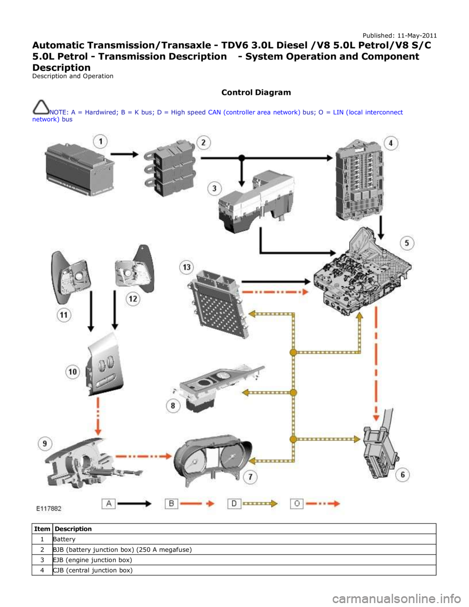
Control Diagram
NOTE: A = Hardwired; B = K bus; D = High speed CAN (controller area network) bus; O = LIN (local interconnect
network) bus
Item Description 1 Battery 2 BJB (battery junction box) (250 A megafuse) 3 EJB (engine junction box) 4 CJB (central junction box)