2010 JAGUAR XFR turn signal
[x] Cancel search: turn signalPage 2152 of 3039
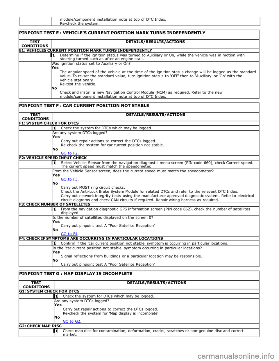
TEST
CONDITIONS DETAILS/RESULTS/ACTIONS E1: VEHICLES CURRENT POSITION MARK TURNS INDEPENDENTLY 1 Determine if the ignition status was turned to Auxiliary or On, while the vehicle was in motion with steering turned such as after an engine stall. Was ignition status set to Auxiliary or On?
Yes
The angular speed of the vehicle at the time of the ignition status change will be logged as the standard
value. To re-set the standard value, turn ignition status to 'OFF' then to 'Auxiliary' or 'On' with the
vehicle stationary.
Re-test the vehicle.
No
Check and install a new Navigation Control Module (NCM) as required. Refer to the new module/component installation note at top of DTC Index.
PINPOINT TEST F : CAR CURRENT POSITION NOT STABLE TEST
CONDITIONS DETAILS/RESULTS/ACTIONS F1: SYSTEM CHECK FOR DTCS 1 Check the system for DTCs which may be logged. Are any system DTCs logged? Yes
Carry out repair actions to correct the DTCs logged.
Re-check the system for car current position not stable.
No
GO to F2. F2: VEHICLE SPEED INPUT CHECK 1 Select Vehicle Sensor from the navigation diagnostic menu screen (PIN code 660), check Current speed. The current speed must match the speedometer. From the Vehicle Sensor screen, does the current speed must match the speedometer? Yes
GO to F3. No
Carry out MOST ring circuit checks.
Check the Anti-Lock Brake System Module for related DTCs and refer to the relevant DTC Index.
Carry out network integrity tests using the manufacturer approved diagnostic system. Refer to electrical
circuit diagrams and check CAN circuits if required. Repair wiring harness as required. F3: CHECK NUMBER OF SATELLITES 1 From the navigation diagnostic GPS information screen (PIN code 662), check the number of satellites displayed. Is the number of satellites displayed on the screen 0? Yes
Carry out pinpoint test A "Poor Satellite Reception"
No
GO to F4. F4: CHECK IF SYMPTOMS ARE OCCURRING IN PARTICULAR LOCATIONS 1 Confirm if the 'car current position not stable' symptom is occurring in particular locations. Is the 'car current position not stable' symptom occurring in particular locations? Yes
Signal reflections from buildings or a particular location may be responsible.
No
Carry out pinpoint test A "Poor Satellite Reception"
PINPOINT TEST G : MAP DISPLAY IS INCOMPLETE TEST
CONDITIONS DETAILS/RESULTS/ACTIONS G1: SYSTEM CHECK FOR DTCS 1 Check the system for DTCs which may be logged. Are any system DTCs logged? Yes
Carry out repair actions to correct the DTCs logged.
Re-check the system for 'Map display is incomplete'.
No
GO to G2. G2: CHECK MAP DISC 1 Check map disc for contamination, deformation, cracks, scratches or non-genuine disc and correct market. module/component installation note at top of DTC Index.
Re-check the system.
Page 2176 of 3039
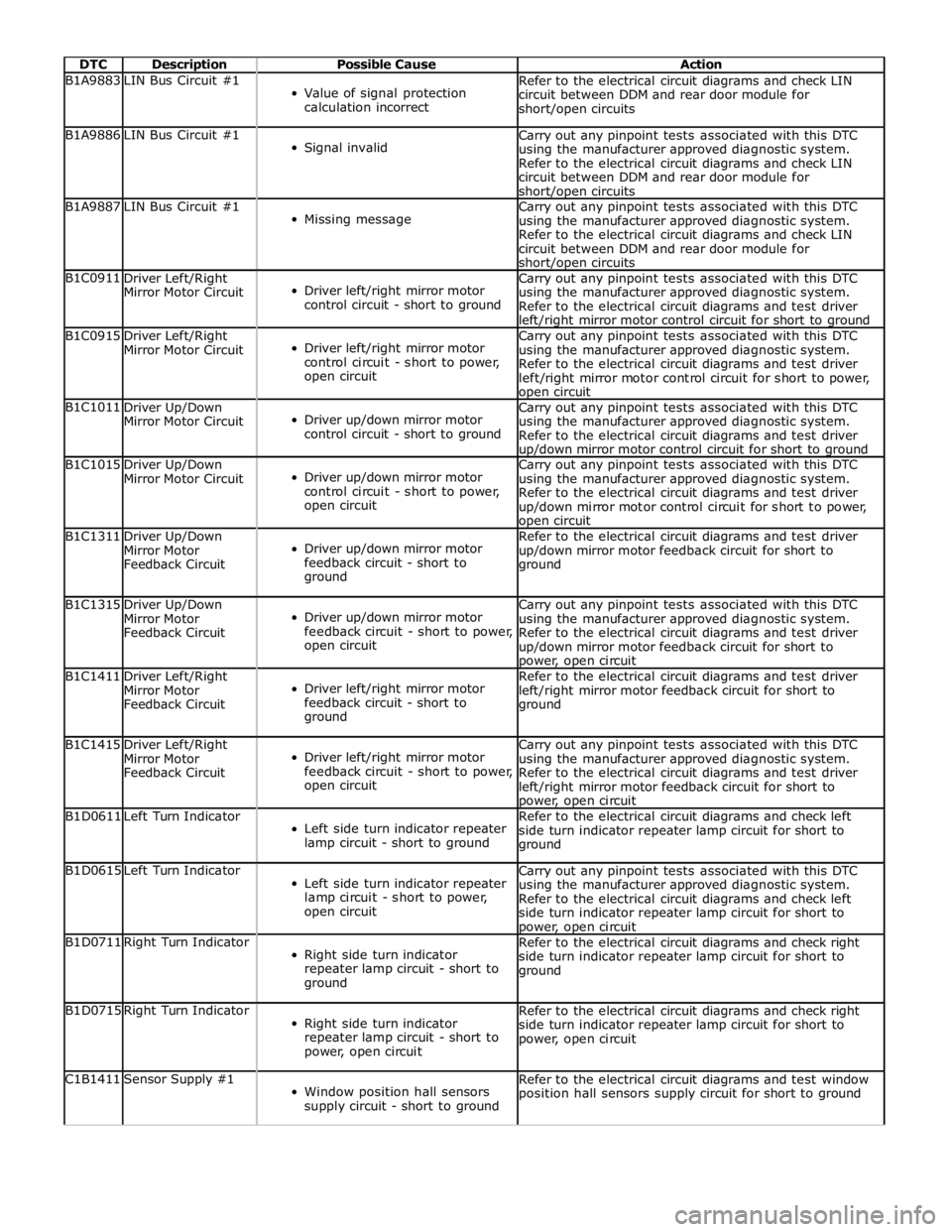
DTC Description Possible Cause Action B1A9883 LIN Bus Circuit #1
Value of signal protection
calculation incorrect Refer to the electrical circuit diagrams and check LIN
circuit between DDM and rear door module for
short/open circuits B1A9886 LIN Bus Circuit #1
Signal invalid Carry out any pinpoint tests associated with this DTC
using the manufacturer approved diagnostic system.
Refer to the electrical circuit diagrams and check LIN
circuit between DDM and rear door module for short/open circuits B1A9887 LIN Bus Circuit #1
Missing message Carry out any pinpoint tests associated with this DTC
using the manufacturer approved diagnostic system.
Refer to the electrical circuit diagrams and check LIN
circuit between DDM and rear door module for short/open circuits B1C0911
Driver Left/Right
Mirror Motor Circuit
Driver left/right mirror motor
control circuit - short to ground Carry out any pinpoint tests associated with this DTC
using the manufacturer approved diagnostic system.
Refer to the electrical circuit diagrams and test driver left/right mirror motor control circuit for short to ground B1C0915
Driver Left/Right
Mirror Motor Circuit
Driver left/right mirror motor
control circuit - short to power,
open circuit Carry out any pinpoint tests associated with this DTC
using the manufacturer approved diagnostic system.
Refer to the electrical circuit diagrams and test driver
left/right mirror motor control circuit for short to power, open circuit B1C1011
Driver Up/Down
Mirror Motor Circuit
Driver up/down mirror motor
control circuit - short to ground Carry out any pinpoint tests associated with this DTC
using the manufacturer approved diagnostic system.
Refer to the electrical circuit diagrams and test driver up/down mirror motor control circuit for short to ground B1C1015
Driver Up/Down
Mirror Motor Circuit
Driver up/down mirror motor
control circuit - short to power,
open circuit Carry out any pinpoint tests associated with this DTC
using the manufacturer approved diagnostic system.
Refer to the electrical circuit diagrams and test driver
up/down mirror motor control circuit for short to power, open circuit B1C1311
Driver Up/Down
Mirror Motor
Feedback Circuit
Driver up/down mirror motor
feedback circuit - short to
ground Refer to the electrical circuit diagrams and test driver
up/down mirror motor feedback circuit for short to
ground B1C1315
Driver Up/Down
Mirror Motor
Feedback Circuit
Driver up/down mirror motor
feedback circuit - short to power,
open circuit Carry out any pinpoint tests associated with this DTC
using the manufacturer approved diagnostic system.
Refer to the electrical circuit diagrams and test driver
up/down mirror motor feedback circuit for short to power, open circuit B1C1411
Driver Left/Right
Mirror Motor
Feedback Circuit
Driver left/right mirror motor
feedback circuit - short to
ground Refer to the electrical circuit diagrams and test driver
left/right mirror motor feedback circuit for short to
ground B1C1415
Driver Left/Right
Mirror Motor
Feedback Circuit
Driver left/right mirror motor
feedback circuit - short to power,
open circuit Carry out any pinpoint tests associated with this DTC
using the manufacturer approved diagnostic system.
Refer to the electrical circuit diagrams and test driver
left/right mirror motor feedback circuit for short to power, open circuit B1D0611 Left Turn Indicator
Left side turn indicator repeater
lamp circuit - short to ground Refer to the electrical circuit diagrams and check left
side turn indicator repeater lamp circuit for short to
ground B1D0615 Left Turn Indicator
Left side turn indicator repeater
lamp circuit - short to power,
open circuit Carry out any pinpoint tests associated with this DTC
using the manufacturer approved diagnostic system.
Refer to the electrical circuit diagrams and check left
side turn indicator repeater lamp circuit for short to power, open circuit B1D0711 Right Turn Indicator
Right side turn indicator
repeater lamp circuit - short to
ground Refer to the electrical circuit diagrams and check right
side turn indicator repeater lamp circuit for short to
ground B1D0715 Right Turn Indicator
Right side turn indicator
repeater lamp circuit - short to
power, open circuit Refer to the electrical circuit diagrams and check right
side turn indicator repeater lamp circuit for short to
power, open circuit C1B1411 Sensor Supply #1
Window position hall sensors
supply circuit - short to ground Refer to the electrical circuit diagrams and test window
position hall sensors supply circuit for short to ground
Page 2185 of 3039

DTC Description Possible Cause Action B1A9883 LIN Bus Circuit #1
Value of signal protection
calculation incorrect Refer to the electrical circuit diagrams and check LIN
circuit between DDM and rear door module for
short/open circuits B1A9886 LIN Bus Circuit #1
Signal invalid Carry out any pinpoint tests associated with this DTC
using the manufacturer approved diagnostic system.
Refer to the electrical circuit diagrams and check LIN
circuit between DDM and rear door module for short/open circuits B1A9887 LIN Bus Circuit #1
Missing message Carry out any pinpoint tests associated with this DTC
using the manufacturer approved diagnostic system.
Refer to the electrical circuit diagrams and check LIN
circuit between DDM and rear door module for short/open circuits B1C1111
Passenger
Left/Right Mirror
Motor Circuit
Passenger left/right mirror motor
control circuit - short to ground Refer to the electrical circuit diagrams and test
passenger left/right mirror motor control circuit for short
to ground B1C1115
Passenger
Left/Right Mirror
Motor Circuit
Passenger left/right mirror motor
control circuit - short to power,
open circuit Carry out any pinpoint tests associated with this DTC
using the manufacturer approved diagnostic system.
Refer to the electrical circuit diagrams and test
passenger left/right mirror motor control circuit for short
to power, open circuit B1C1211
Passenger Up/Down
Mirror Motor Circuit
Passenger up/down mirror motor
control circuit - short to ground Refer to the electrical circuit diagrams and test
passenger up/down mirror motor control circuit for short
to ground B1C1215
Passenger Up/Down
Mirror Motor Circuit
Passenger up/down mirror motor
control circuit - short to power,
open circuit Carry out any pinpoint tests associated with this DTC
using the manufacturer approved diagnostic system.
Refer to the electrical circuit diagrams and test
passenger up/down mirror motor control circuit for short
to power, open circuit B1C1511
Passenger Up/Down
Mirror Motor
Feedback Circuit
Passenger up/down mirror motor
feedback circuit - short to
ground Refer to the electrical circuit diagrams and test
passenger up/down mirror motor feedback circuit for
short to ground B1C1515
Passenger Up/Down
Mirror Motor
Feedback Circuit
Passenger up/down mirror motor
feedback circuit - short to power,
open circuit Refer to the electrical circuit diagrams and test
passenger up/down mirror motor feedback circuit for
short to power, open circuit B1C1611
Passenger
Left/Right Mirror
Motor Feedback
Circuit
Passenger left/right mirror motor
feedback circuit - short to ground Refer to the electrical circuit diagrams and test
passenger left/right mirror motor feedback circuit for
short to ground B1C1615
Passenger
Left/Right Mirror
Motor Feedback
Circuit
Passenger left/right mirror motor
feedback circuit - short to power,
open circuit Refer to the electrical circuit diagrams and test
passenger left/right mirror motor feedback circuit for
short to power, open circuit B1D0611 Left Turn Indicator
Left side turn indicator repeater
lamp circuit - short to ground Refer to the electrical circuit diagrams and check left
side turn indicator repeater lamp circuit for short to
ground B1D0615 Left Turn Indicator
Left side turn indicator repeater
lamp circuit - short to power,
open circuit Carry out any pinpoint tests associated with this DTC
using the manufacturer approved diagnostic system.
Refer to the electrical circuit diagrams and check left
side turn indicator repeater lamp circuit for short to power, open circuit B1D0711 Right Turn Indicator
Right side turn indicator
repeater lamp circuit - short to
ground Refer to the electrical circuit diagrams and check right
side turn indicator repeater lamp circuit for short to
ground B1D0715 Right Turn Indicator
Right side turn indicator
repeater lamp circuit - short to
power, open circuit Refer to the electrical circuit diagrams and check right
side turn indicator repeater lamp circuit for short to
power, open circuit C1B1411 Sensor Supply #1
Front window position hall
sensor supply circuit - short to
ground Refer to the electrical circuit diagrams and test front
window position hall sensor supply circuit for short to
ground www.JagDocs.com
Page 2292 of 3039

Rear View Mirrors - Rear View Mirrors - Overview
Description and Operation
Overview
The exterior mirrors incorporate the following:
Blind spot monitoring indicator
Auto dimming function
Turn signal indicators
Approach lamps
Exterior temperature sensor
Heated mirror function
Reverse dipping function Published: 11-May-2011
Movement of the door mirrors is controlled from a switch pack located on the drivers door. The switch pack contains 2
non-latching mirror select buttons labeled 'L' and 'R' and a 4-way mirror movement switch. Door mirror movement commands
are transmitted to the driver's door module over the LIN (local interconnect network) bus. The drivers door module transmits
any mirror movement commands to the passenger door module over the medium speed CAN (controller area network) bus.
Movement of the door mirrors is carried out by the respective door module. The door modules provide supply and ground paths
to the mirror motors and monitor mirror position via potentiometers located in the mirror housings.
Both exterior door mirrors and the interior mirror feature an auto dimming function. The interior rear view mirror contains one
forward and one reward facing light sensor. The light sensors control the auto dimming feature of the interior mirror to reduce
glare from the headlights of following vehicles.
When auto-dimming of the interior mirror is required, a supply is provided by the interior mirror to both door mirrors to initiate
the door mirror auto-dimming sequence.
Blind spot monitoring function alerts the driver to a vehicle located in the vehicle blind spot. A warning indicator is located in
each exterior mirror towards the outer edge.
Refer to: Blindspot Monitoring System (413-09 Warning Devices, Description and Operation).
Page 2315 of 3039
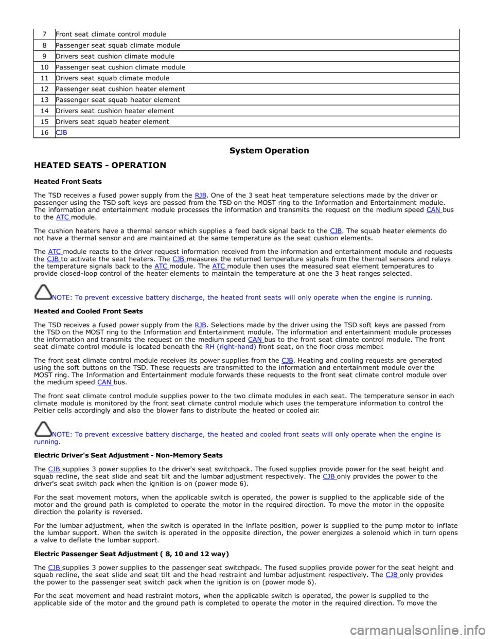
7 Front seat climate control module 8 Passenger seat squab climate module 9 Drivers seat cushion climate module 10 Passenger seat cushion climate module 11 Drivers seat squab climate module 12 Passenger seat cushion heater element 13 Passenger seat squab heater element 14 Drivers seat cushion heater element 15 Drivers seat squab heater element 16 CJB
HEATED SEATS - OPERATION
Heated Front Seats System Operation
The TSD receives a fused power supply from the RJB. One of the 3 seat heat temperature selections made by the driver or passenger using the TSD soft keys are passed from the TSD on the MOST ring to the Information and Entertainment module.
The information and entertainment module processes the information and transmits the request on the medium speed CAN bus to the ATC module.
The cushion heaters have a thermal sensor which supplies a feed back signal back to the CJB. The squab heater elements do not have a thermal sensor and are maintained at the same temperature as the seat cushion elements.
The ATC module reacts to the driver request information received from the information and entertainment module and requests the CJB to activate the seat heaters. The CJB measures the returned temperature signals from the thermal sensors and relays the temperature signals back to the ATC module. The ATC module then uses the measured seat element temperatures to provide closed-loop control of the heater elements to maintain the temperature at one the 3 heat ranges selected.
NOTE: To prevent excessive battery discharge, the heated front seats will only operate when the engine is running.
Heated and Cooled Front Seats
The TSD receives a fused power supply from the RJB. Selections made by the driver using the TSD soft keys are passed from the TSD on the MOST ring to the Information and Entertainment module. The information and entertainment module processes
the information and transmits the request on the medium speed CAN bus to the front seat climate control module. The front seat climate control module is located beneath the RH (right-hand) front seat, on the floor cross member.
The front seat climate control module receives its power supplies from the CJB. Heating and cooling requests are generated using the soft buttons on the TSD. These requests are transmitted to the information and entertainment module over the
MOST ring. The Information and Entertainment module forwards these requests to the front seat climate control module over
the medium speed CAN bus.
The front seat climate control module supplies power to the two climate modules in each seat. The temperature sensor in each
climate module is monitored by the front seat climate control module which uses the temperature information to control the
Peltier cells accordingly and also the blower fans to distribute the heated or cooled air.
NOTE: To prevent excessive battery discharge, the heated and cooled front seats will only operate when the engine is
running.
Electric Driver's Seat Adjustment - Non-Memory Seats
The CJB supplies 3 power supplies to the driver's seat switchpack. The fused supplies provide power for the seat height and squab recline, the seat slide and seat tilt and the lumbar adjustment respectively. The CJB only provides the power to the driver's seat switch pack when the ignition is on (power mode 6).
For the seat movement motors, when the applicable switch is operated, the power is supplied to the applicable side of the
motor and the ground path is completed to operate the motor in the required direction. To move the motor in the opposite
direction the polarity is reversed.
For the lumbar adjustment, when the switch is operated in the inflate position, power is supplied to the pump motor to inflate
the lumbar support. When the switch is operated in the opposite direction, the power energizes a solenoid which in turn opens
a valve to deflate the lumbar support.
Electric Passenger Seat Adjustment ( 8, 10 and 12 way)
The CJB supplies 3 power supplies to the passenger seat switchpack. The fused supplies provide power for the seat height and squab recline, the seat slide and seat tilt and the head restraint and lumbar adjustment respectively. The CJB only provides the power to the passenger seat switch pack when the ignition is on (power mode 6).
For the seat movement and head restraint motors, when the applicable switch is operated, the power is supplied to the
applicable side of the motor and the ground path is completed to operate the motor in the required direction. To move the
Page 2504 of 3039
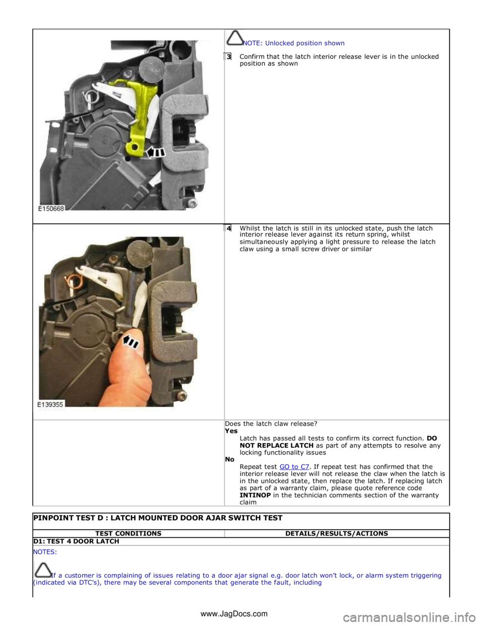
NOTE: Unlocked position shown 3 Confirm that the latch interior release lever is in the unlocked position as shown
4 Whilst the latch is still in its unlocked state, push the latch interior release lever against its return spring, whilst
simultaneously applying a light pressure to release the latch
claw using a small screw driver or similar Does the latch claw release? Yes
Latch has passed all tests to confirm its correct function. DO
NOT REPLACE LATCH as part of any attempts to resolve any
locking functionality issues
No
Repeat test GO to C7. If repeat test has confirmed that the interior release lever will not release the claw when the latch is
in the unlocked state, then replace the latch. If replacing latch
as part of a warranty claim, please quote reference code
INTINOP in the technician comments section of the warranty
claim
PINPOINT TEST D : LATCH MOUNTED DOOR AJAR SWITCH TEST TEST CONDITIONS DETAILS/RESULTS/ACTIONS D1: TEST 4 DOOR LATCH NOTES:
If a customer is complaining of issues relating to a door ajar signal e.g. door latch won’t lock, or alarm system triggering
(indicated via DTC’s), there may be several components that generate the fault, including www.JagDocs.com
Page 2562 of 3039

Roof opening panel System Operation
Operation of the roof opening panel is controlled by the roof opening panel control module, which is integral with the motor.
The control module receives inputs from the CJB, which provides an 'open' or 'close' signal for remote handset operation, and
an 'enable' signal when the vehicle enters power mode 6.
The control module also receives a vehicle speed signal from the ABS module. The vehicle speed signal is used by the control
module to calibrate the anti-trap feature.
If the battery is disconnected, or the power supply is interrupted while the roof opening panel is in a partially open position,
the motor and control module will need to be calibrated to restore full functionality. To recalibrate:
1. Switch ignition on.
2. Press the front of the switch, so the roof opening panel is the tilt position, and then release the switch.
3. Press the front of the switch and hold for thirty seconds.
4. After thirty seconds the roof opening panel will begin to move. Keep the front of the switch pressed until the roof
opening panel has fully opened and then closed.
5. Once the open/close cycle has completed and the roof opening panel has stopped moving, release the switch.
6. The roof opening panel can now be operated as normal.
Drain hoses are connected to the front and rear corners of the roof opening panel frame. The drain hoses are located inside of
the cabin on the 'A' and 'D' post pillars to allow water, which has collected in the frame, to escape. One-way valves fitted to
the end of each drain hose, prevent the ingress of dirt and moisture.
Rear window sunblind
The powered rear window sunblind is operated through a switch in the roof console. Power to the sunblind motor is provided by
a pair of relays located in the CJB when the vehicle enters power mode 4. The sunblind motor is located beneath the rear parcel
shelf and is supplied as a sealed unit with the sunblind mechanism.
If the battery is disconnected or a replacement sunblind is fitted, the motor will require re-calibrating. To re-calibrate the
motor the sunblind should be powered through two-full cycles of movement.
Roof opening panel, motor Component Description
The roof opening panel motor has a worm drive which drives a gear in the cast housing attached to the end of the motor. The
gear has a small pinion gear attached to the outer part of its spindle. The pinion engages with two cables to form a rack and
pinion drive. Rotation of the motor turns the pinion which in turn drives the cables in the required direction.
The two cables are attached either side of the pinion. One end of each cable is attached to the guide; the opposite end of
each cable is held in position on the pinion by a metal insert in the frame. The cables run in channels, in the panel frame to
the guides. As the panel is closed the cables are pushed through channels in the front of the frame. The displaced cable is
guided into a further two channels in the frame, which protect the cable and prevent it from snagging. The cables
manufactured from rigid spring steel can pull as well as push the panel along the guides.
The motor contains a micro-switch and Hall effect sensor. Signals received from these components enable the control module
to calculate the exact position of the roof opening panel. The Hall effect sensor is also responsible for the operation of the
anti-trap function.
If the anti-trap feature is activated while the roof opening panel is closing, the panel is reversed for 200mm or as far as
possible. The Hall effect sensor, located in the motor, monitors the speed of the motor and if the speed decreases below a set
threshold, indicating an obstruction, the power feed to the motor is reversed so the panel goes back. In an emergency the
anti-trap function can be overridden by holding the switch in the closed position.
Roof opening panel, control module
The roof opening panel control module is integrated within the motor. The control module receives inputs from the CJB, which
provides an 'open' or 'close' signal for remote handset operation, and an 'enable' signal when the vehicle enters power mode 6.
The control module also contains the algorithm for the anti-trap system and receives a vehicle speed signal from the ABS
module. The vehicle speed signal is used by the control module to calibrate the anti-trap feature.
Page 2615 of 3039
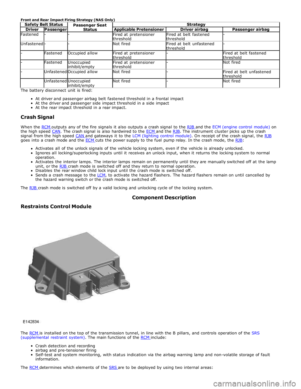
Driver Passenger Applicable Pretensioner Driver airbag Passenger airbag Fastened - -
Fired at pretensioner
threshold Fired at belt fastened
threshold - Unfastened - - Not fired
Fired at belt unfastened
threshold - - Fastened Occupied allow
Fired at pretensioner
threshold -
Fired at belt fastened
threshold - Fastened
Unoccupied inhibit/empty Fired at pretensioner
threshold - Not fired - Unfastened Occupied allow Not fired -
Fired at belt unfastened
threshold Unfastened
Unoccupied inhibit/empty Not fired - Not fired The battery disconnect unit is fired:
At driver and passenger airbag belt fastened threshold in a frontal impact
At the driver and passenger side impact threshold in a side impact
At the rear impact threshold in a rear impact.
Crash Signal
When the RCM outputs any of the fire signals it also outputs a crash signal to the RJB and the ECM (engine control module) on the high speed CAN. The crash signal is also hardwired to the ECM and the RJB. The instrument cluster picks up the crash signal from the high speed CAN and gateways it to the LCM (lighting control module). On receipt of the crash signal, the RJB goes into a crash mode and the ECM cuts the power supply to the fuel pump relay. In the crash mode, the RJB: Activates all of the unlock signals of the vehicle locking system, even if the vehicle is already unlocked.
Ignores all locking/superlocking inputs until it receives an unlock input, when it returns the locking system to normal
operation.
Activates the interior lamps. The interior lamps remain on permanently until they are manually switched off at the lamp
unit, or the RJB crash mode is switched off and they return to normal operation. Disables the rear window child lock input until the crash mode is switched off.
Sends a crash message to the LCM, to activate the hazard flashers. The hazard flashers remain on until cancelled by the hazard warning switch or the crash mode is switched off.
The RJB crash mode is switched off by a valid locking and unlocking cycle of the locking system.
Restraints Control Module Component Description
The RCM is installed on the top of the transmission tunnel, in line with the B pillars, and controls operation of the SRS (supplemental restraint system). The main functions of the RCM include:
Crash detection and recording
airbag and pre-tensioner firing
Self-test and system monitoring, with status indication via the airbag warning lamp and non-volatile storage of fault
information.
The RCM determines which elements of the SRS are to be deployed by using two internal areas: