Page 2072 of 3039
Tire Pressure Monitoring System (TPMS) module 15 Driver's door control module 16 LH blind spot monitoring module CONTROL DIAGRAM - HIGH SPEED CAN BUS
Item Description D = High speed CAN bus 1 Electric steering column lock 2 Instrument cluster 3 Diagnostic socket 4 Adaptive speed control module 5 Electronic transmission selector 6 Occupant classification system control module 7 Headlamp leveling module 8 ABS (anti-lock brake system) module
Page 2166 of 3039
Tire Pressure Monitoring System (TPMS) control module 15 Entertainment system control module 16 Climate seat module COMPONENT LOCATION - HIGH SPEED CAN BUS
Item Description NOTE: LHD vehicle shown 1 ECM - V8 shown 2 Headlamp leveling control module 3 Occupant classification system control module 4 Adaptive damping control module 5 Instrument cluster 6 Electronic transmission selector 7 Electronic Parking Brake (EPB) module 8 RCM (restraints control module)
Page 2171 of 3039

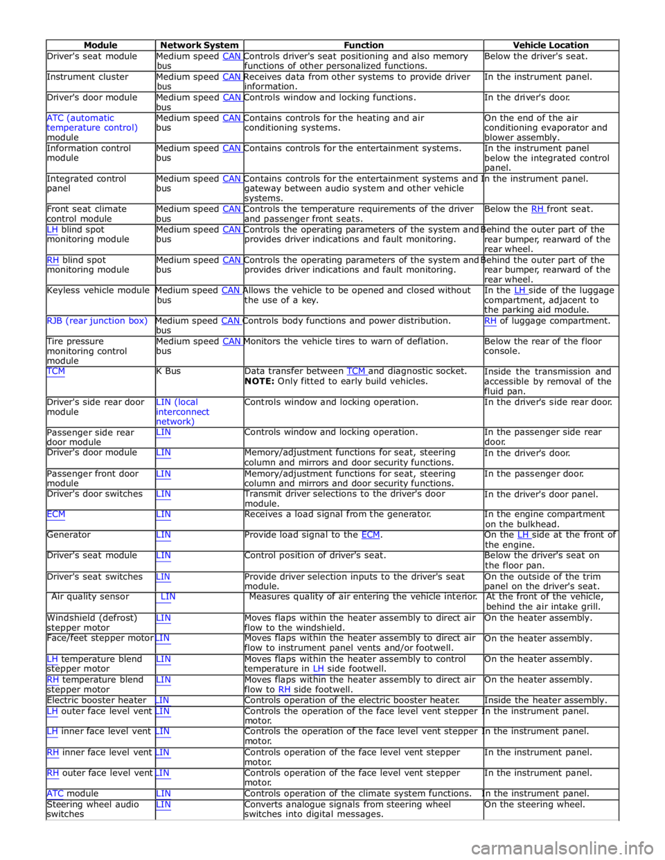
Module Network System Function Vehicle Location
Driver's seat module Medium speed CAN Controls driver's seat positioning and also memory Below the driver's seat. bus functions of other personalized functions.
Instrument cluster Medium speed CAN Receives data from other systems to provide driver In the instrument panel. bus information.
Driver's door module Medium speed CAN Controls window and locking functions. In the driver's door. bus
ATC (automatic Medium speed CAN Contains controls for the heating and air On the end of the air
temperature control)
module bus conditioning systems.
conditioning evaporator and
blower assembly.
Information control Medium speed CAN Contains controls for the entertainment systems. In the instrument panel module bus
below the integrated control
panel.
Integrated control Medium speed CAN Contains controls for the entertainment systems and In the instrument panel. panel bus
gateway between audio system and other vehicle
systems.
Front seat climate Medium speed CAN Controls the temperature requirements of the driver Below the RH front seat. control module bus and passenger front seats.
LH blind spot Medium speed CAN Controls the operating parameters of the system and Behind the outer part of the monitoring module bus provides driver indications and fault monitoring.
rear bumper, rearward of the
rear wheel.
RH blind spot Medium speed CAN Controls the operating parameters of the system and Behind the outer part of the monitoring module bus provides driver indications and fault monitoring.
rear bumper, rearward of the
rear wheel.
Keyless vehicle module Medium speed CAN Allows the vehicle to be opened and closed without In the LH side of the luggage bus the use of a key.
compartment, adjacent to
the parking aid module.
RJB (rear junction box) Medium speed CAN Controls body functions and power distribution. RH of luggage compartment. bus
Tire pressure Medium speed CAN Monitors the vehicle tires to warn of deflation. Below the rear of the floor monitoring control
module bus console.
TCM K Bus Data transfer between TCM and diagnostic socket. NOTE: Only fitted to early build vehicles. Inside the transmission and
accessible by removal of the
fluid pan.
Driver's side rear door
module LIN (local
interconnect
network) Controls window and locking operation. In the driver's side rear door.
Passenger side rear
door module LIN Controls window and locking operation. In the passenger side rear
door.
Driver's door module LIN Memory/adjustment functions for seat, steering
column and mirrors and door security functions. In the driver's door.
Passenger front door
module LIN Memory/adjustment functions for seat, steering
column and mirrors and door security functions. In the passenger door.
Driver's door switches LIN Transmit driver selections to the driver's door
module. In the driver's door panel.
ECM LIN Receives a load signal from the generator. In the engine compartment
on the bulkhead.
Generator LIN Provide load signal to the ECM. On the LH side at the front of the engine.
Driver's seat module LIN Control position of driver's seat. Below the driver's seat on
the floor pan.
Driver's seat switches LIN Provide driver selection inputs to the driver's seat
module. On the outside of the trim
panel on the driver's seat.
Air quality sensor LIN Measures quality of air entering the vehicle interior. At the front of the vehicle,
behind the air intake grill.
Windshield (defrost)
stepper motor LIN Moves flaps within the heater assembly to direct air
flow to the windshield. On the heater assembly.
Face/feet stepper motor LIN Moves flaps within the heater assembly to direct air
flow to instrument panel vents and/or footwell. On the heater assembly.
LH temperature blend
stepper motor
RH temperature blend
stepper motor LIN Moves flaps within the heater assembly to control
temperature in LH side footwell.
LIN Moves flaps within the heater assembly to direct air
flow to RH side footwell. On the heater assembly.
On the heater assembly.
Electric booster heater LIN Controls operation of the electric booster heater. Inside the heater assembly.
LH outer face level vent LIN Controls the operation of the face level vent stepper In the instrument panel.
motor.
LH inner face level vent LIN Controls the operation of the face level vent stepper In the instrument panel.
motor.
RH inner face level vent LIN Controls operation of the face level vent stepper
motor.
RH outer face level vent LIN Controls operation of the face level vent stepper
motor. In the instrument panel.
In the instrument panel.
ATC module LIN Controls operation of the climate system functions. In the instrument panel.
Steering wheel audio
switches LIN Converts analogue signals from steering wheel
switches into digital messages. On the steering wheel.
Page 2540 of 3039

and is connected at the opposite end to the LH pivot housing via a crank. The LH pivot housing crank is fitted with a second link rod which is connected directly to the crank on the RH pivot housing.
The motor crank converts rotary motion from the motor output shaft into linear movement of the link rods. The cranks
connected to each pivot housing, convert the linear motion of the link rods back to rotary motion of the pivot housings. This
rotary motion is passed to the wiper arms and blades causing the blades to wipe an arc across the windshield.
Each wiper arm is located on a taper spline on the respective pivot housing. A nut is screwed on the end of the pivot housing
shaft and positively secures the wiper arm on the taper spline.
The wiper blades are attached to the wiper arms with a quick release fittings. The blades are of the flat blade type. These
blades have an integral spring along their full length which curves the blade to match the windshield and provides even blade
to windshield contact pressure along the entire length of the blade.
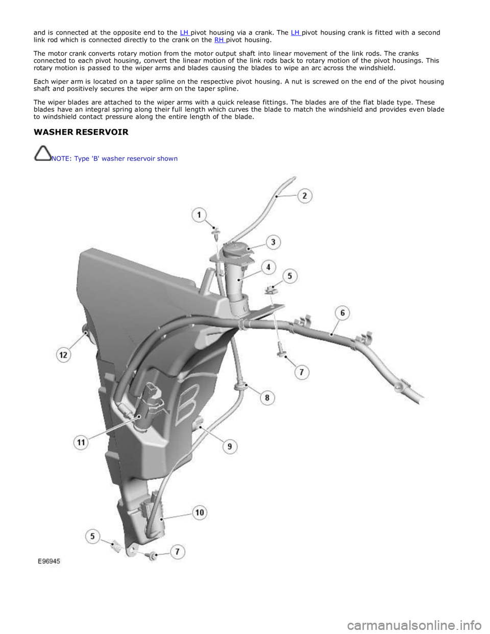
WASHER RESERVOIR
NOTE: Type 'B' washer reservoir shown