POWER SUPPLY AND GROUND CIRCUITDLK-69
< COMPONENT DIAGNOSIS > [WITH INTELLIGENT KEY SYSTEM]
C
D
E
F
G H
I
J
L
M A
B
DLK
N
O P
YES >> Replace the blown fuse or fusible link after repairing the affected circuit.
NO >> GO TO 2
2. CHECK POWER SUPPLY CIRCUIT
1. Turn ignition switch OFF.
2. Disconnect BCM.
3. Check voltage between BCM harness connector and ground.
Is the measurement value normal?
YES >> GO TO 3
NO >> Repair or replace harness.
3. CHECK GROUND CIRCUIT
Check continuity between BCM harness connector and ground.
Does continuity exist?
YES >> Inspection End.
NO >> Repair or replace harness.
BACK DOOR CONTROL UNIT
BACK DOOR CONTROL UNIT : Diagnosis ProcedureINFOID:0000000005146925
Regarding Wiring Diagram information, refer to DLK-199, "Wiring Diagram—AUTOMATIC BACK DOOR SYS-
TEM—".
1.BACK DOOR POWER SUPPLY CIRCUIT INSPECTION
1. Turn ignition switch OFF.
2. Disconnect back door control unit connector.
Connector Te r m i n a l s
Power
source Condition Voltage (V) (Ap-
prox.)
(+) (-)
M18 11 Ground
ACC
power
supply Ignition
switch
ACC or
ON Battery voltage
38 Ground Ignition
power
supply Ignition
switch ON or START Battery voltage
M20 57 Ground
Battery
power
supply Ignition
switch OFF Battery voltage
70 Ground Battery
power
supply Ignition
switch
OFF Battery voltage
LIIA2415E
BCM
GroundContinuity
Connector Terminal
M20 67 Yes
LIIA0915E
Revision: April 20092010 QX56
DLK-214
< SYMPTOM DIAGNOSIS >[WITH INTELLIGENT KEY SYSTEM]
BACK DOOR OPENER FUNCTION
BACK DOOR OPENER FUNCTION
BACK DOOR OPENER SWITCH
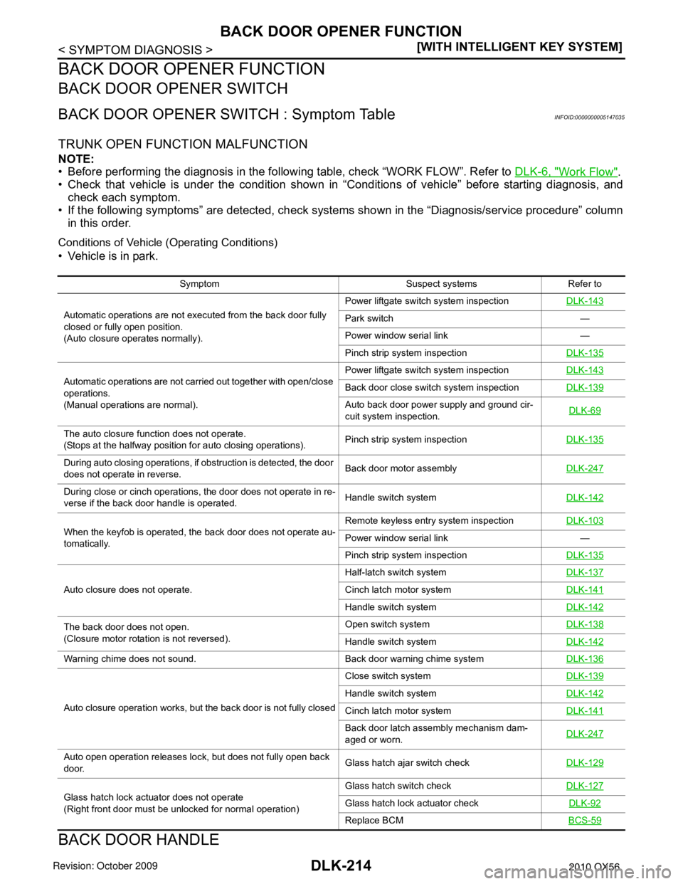
BACK DOOR OPENER SWITCH : Symptom TableINFOID:0000000005147035
TRUNK OPEN FUNCTION MALFUNCTION
NOTE:
• Before performing the diagnosis in the following table, check “WORK FLOW”. Refer to
DLK-6, "
Work Flow".
• Check that vehicle is under the condition shown in “Conditions of vehicle” before starting diagnosis, and
check each symptom.
• If the following symptoms” are detected, check systems shown in the “Diagnosis/service procedure” column in this order.
Conditions of Vehicle (Operating Conditions)
• Vehicle is in park.
BACK DOOR HANDLE
Symptom Suspect systemsRefer to
Automatic operations are not executed from the back door fully
closed or fully open position.
(Auto closure operates normally). Power liftgate switch system inspection
DLK-143
Park switch —
Power window serial link —
Pinch strip system inspection DLK-135
Automatic operations are not carried out together with open/close
operations.
(Manual operations are normal). Power liftgate switch system inspection
DLK-143Back door close switch system inspectionDLK-139
Auto back door power supply and ground cir-
cuit system inspection. DLK-69
The auto closure function does not operate.
(Stops at the halfway position for auto closing operations).
Pinch strip system inspection
DLK-135
During auto closing operations, if obstruction is detected, the door
does not operate in reverse. Back door motor assembly
DLK-247
During close or cinch operations, the door does not operate in re-
verse if the back door handle is operated. Handle switch system
DLK-142
When the keyfob is operated, the back door does not operate au-
tomatically. Remote keyless entry system inspection
DLK-103Power window serial link —
Pinch strip system inspection DLK-135
Auto closure does not operate. Half-latch switch system
DLK-137Cinch latch motor systemDLK-141
Handle switch systemDLK-142
The back door does not open.
(Closure motor rotation is not reversed). Open switch system
DLK-138
Handle switch systemDLK-142
Warning chime does not sound. Back door warning chime systemDLK-136
Auto closure operation works, but the back door is not fully closed Close switch system
DLK-139
Handle switch systemDLK-142
Cinch latch motor systemDLK-141
Back door latch assembly mechanism dam-
aged or worn.DLK-247
Auto open operation releases lock, but does not fully open back
door. Glass hatch ajar switch check
DLK-129
Glass hatch lock actuator does not operate
(Right front door must be unlocked for normal operation) Glass hatch switch check
DLK-127Glass hatch lock actuator check DLK-92
Replace BCMBCS-59
Revision: April 20092010 QX56