Page 2958 of 4210
PG-48
< COMPONENT DIAGNOSIS >
HARNESS
ENGINE CONTROL HARNESS
A3 E34 W/24 : To B40F3 E142 W/24 : Transfer control unit
A4 E35 W/12 : To B41 F3 E143 GR/24 : Transfer control unit
A4 E36 W/2 : To B42 G3 E152 SMJ : To M31
B3 E37 BR/2 : ASCD brake switch (with ASCD)
ABMIA1202GB
Revision: April 20092010 QX56
Page 2959 of 4210

PG
HARNESSPG-49
< COMPONENT DIAGNOSIS >
C
DE
F
G H
I
J
K L
B A
O P
N
D5 F3 B/1 : A/C Compressor
D4 F42 GR/2 : Fuel injector No. 5
D5 F4 GR/1 : Oil pressure switch D3 F45 GR/2 : Fuel injector No. 7
D2 F5 GR/4 : Air fuel ratio (A/F) sensor 1 (ban k 2) B4 F46 B/3 : Power steering pressure sensor
C4 F6 GR/3 : Ignition coil No. 2 (with power transistor) E4 F47 GR/3 : Ignition coil No. 1 (with power transistor)
C3 F7 GR/3 : Ignition coil No. 4 (with power transistor) E4 F48 GR/3 : Ignition coil No. 3 (with power transistor)
C3 F8 GR/3 : Ignition coil No. 6 (with power transistor) E4 F49 GR/3 : Ignition coil No. 5 (with power transistor)
E2 F9 G/10 : A/T assembly D4 F50 B/6 : Electric throttle control actuator
C3 F10 — : Engine ground E4 F51 GR/3 : Ignition coil No. 7 (with power transistor)
D3 F11 B/3 : Crankshaft position sensor (POS) D2 F52 GR/3 : Ignition coil No. 8 (with power transistor)
E1 F12 G/4 : Heated oxygen sensor 2 (bank 2) E5 F53 B/6 : Mass air flow sensor
F2 F13 G/4 : Heated oxygen sensor 2 (bank 1) B2 F54 B/81 : ECM
B2 F14 W/24 : To E5 F1 F55 B/2 : ATP switch
D4 F15 GR/2 : EVAP canister purge volume control
solenoid valve F2 F56 B/8 : Transfer terminal cord assembly
E5 F16 — : Engine ground G1 F57 B/2 : Transfer motor
C4 F18 GR/2 : Fuel injector No. 2 F2 F58 GR/6 : Transfer control device
D4 F20 GR/2 : Fuel injector No. 4 F2 F59 B/2 : Wait detection switch
F4 F21 GR/2 : Condenser-1 F1 F60 GR/2 : Neutral-4LO switch
D3 F22 GR/2 : Fuel inje ctor No. 6 D5 F61 G/2: Intake valve timing control solenoid valve
(bank 1)
D4 F23 B/3 : Camshaft position sensor (phase) D5 F62 B/3 : Intake valve timing control position sensor
(bank 1)
D4 F26 B/6 : To F101 C4 F63 G/2: Intake valve timing control solenoid valve
(bank 2)
E3 F27 /1 : Starter motor C4 F64 B/3: Intake valve timing control position sensor
(bank 2)
E3 F28 GR/1 : Starter motor E3 F65 GR/4 : Air fuel ratio (A/F) sensor 1 (bank 1)
D4 F30 GR/2 : Fuel injector No. 1 C2 F68 GR/2 : Water valve
D3 F31 GR/2 : Fuel injector No. 8 Engine control sub-harness
B2 F32 W/16 : To E2 C3 F101 B/6 : To F26
C2 F33 W/16 : To E19 C3 F102 B/2 : Knock sensor (bank 1)
C2 F34 W/2 : To E39 C3 F103 GR/2 : Engine coolant temperature sensor
B3 F39 /1 : Fusible link box (battery) C3 F104 B/2 : Knock sensor (bank 2)
D4 F41 GR/2 : Fuel injector No. 3
Revision: April 20092010 QX56
Page 2971 of 4210
PG
ELECTRICAL UNITS LOCATIONPG-61
< COMPONENT DIAGNOSIS >
C
DE
F
G H
I
J
K L
B A
O P
N
ELECTRICAL UNITS LOCATION
Electrical Units LocationINFOID:0000000005146583
ENGINE COMPARTMENT
ABMIA1205GB
Revision: April 20092010 QX56
Page 2982 of 4210
PG-72
< COMPONENT DIAGNOSIS >
IPDM E/R (INTELLIGENT POWER DISTRIBUTION MODULE ENGINE ROOM)
IPDM E/R (INTELLIGENT POWER DISTRIBUTION MODULE ENGINE
ROOM)
IPDM E/R Terminal Arrangement - Type AINFOID:0000000005370327
WKIA5852E
Revision: April 20092010 QX56
Page 2983 of 4210
PG
IPDM E/R (INTELLIGENT POWER DISTRIBUTION MODULE ENGINE ROOM)
PG-73
< COMPONENT DIAGNOSIS >
C
D E
F
G H
I
J
K L
B A
O P
N
IPDM E/R Terminal Ar
rangement - Type BINFOID:0000000005370328
NOTE:
Numbers preceded by an "F" represent the fuse number s imprinted on the IPDM E/R. The other numbers
represent the fuse numbers as they appear in the wiring diagrams.
AAMIA0364GB
Revision: April 20092010 QX56
Page 3066 of 4210

BCM (BODY CONTROL MODULE)PWC-81
< ECU DIAGNOSIS >
C
DE
F
G H
I
J
L
M A
B
PWC
N
O P
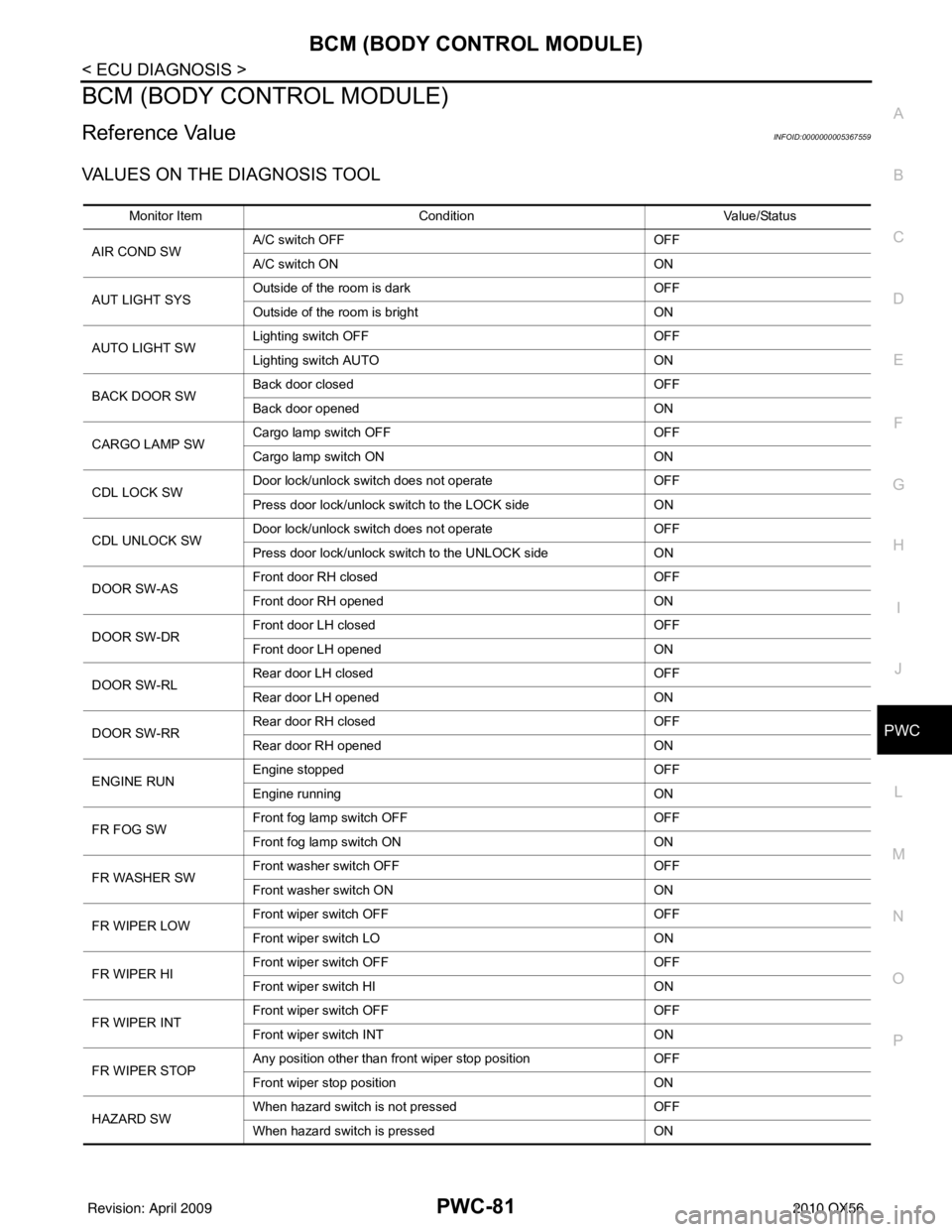
BCM (BODY CONTROL MODULE)
Reference ValueINFOID:0000000005367559
VALUES ON THE DIAGNOSIS TOOL
Monitor Item Condition Value/Status
AIR COND SW A/C switch OFF
OFF
A/C switch ON ON
AUT LIGHT SYS Outside of the room is dark
OFF
Outside of the room is bright ON
AUTO LIGHT SW Lighting switch OFF
OFF
Lighting switch AUTO ON
BACK DOOR SW Back door closed
OFF
Back door opened ON
CARGO LAMP SW Cargo lamp switch OFF
OFF
Cargo lamp switch ON ON
CDL LOCK SW Door lock/unlock switch does not operate
OFF
Press door lock/unlock switch to the LOCK side ON
CDL UNLOCK SW Door lock/unlock switch does not operate
OFF
Press door lock/unlock switch to the UNLOCK side ON
DOOR SW-AS Front door RH closed
OFF
Front door RH opened ON
DOOR SW-DR Front door LH closed
OFF
Front door LH opened ON
DOOR SW-RL Rear door LH closed
OFF
Rear door LH opened ON
DOOR SW-RR Rear door RH closed
OFF
Rear door RH opened ON
ENGINE RUN Engine stopped
OFF
Engine running ON
FR FOG SW Front fog lamp switch OFF
OFF
Front fog lamp switch ON ON
FR WASHER SW Front washer switch OFF
OFF
Front washer switch ON ON
FR WIPER LOW Front wiper switch OFF
OFF
Front wiper switch LO ON
FR WIPER HI Front wiper switch OFF
OFF
Front wiper switch HI ON
FR WIPER INT Front wiper switch OFF
OFF
Front wiper switch INT ON
FR WIPER STOP Any position other than front wiper stop position
OFF
Front wiper stop position ON
HAZARD SW When hazard switch is not pressed
OFF
When hazard switch is pressed ON
Revision: April 20092010 QX56
Page 3067 of 4210

PWC-82
< ECU DIAGNOSIS >
BCM (BODY CONTROL MODULE)
LIGHT SW 1STLighting switch OFF OFF
Lighting switch 1st
ON
HEAD LAMP SW1 Headlamp switch OFF
OFF
Headlamp switch 1st ON
HEAD LAMP SW2 Headlamp switch OFF
OFF
Headlamp switch 1st ON
HI BEAM SW High beam switch OFF
OFF
High beam switch HI ON
IGN ON SW Ignition switch OFF or ACC
OFF
Ignition switch ON ON
IGN SW CAN Ignition switch OFF or ACC
OFF
Ignition switch ON ON
INT VOLUME Wiper intermittent dial is in a dial position 1 - 7 1 - 7
I-KEY LOCK LOCK button of Intelligent Key is not pressed
OFF
LOCK button of Intelligent Key is pressed ON
I-KEY UNLOCK UNLOCK button of Intelligent Key is not pressed
OFF
UNLOCK button of Intelligent Key is pressed ON
KEY CYL LK-SW Door key cylinder LOCK position
ON
Door key cylinder other than LOCK position OF
KEY CYL UN-SW Door key cylinder UNLOCK position
ON
Door key cylinder other than UNLOCK position ON
KEY ON SW Mechanical key is removed from key cylinder
OFF
Mechanical key is inserted to key cylinder ON
OIL PRESS SW • Ignition switch OFF or ACC
• Engine running
OFF
Ignition switch ON ON
OPTICAL SENSOR Bright outside of the vehicle
Close to 5V
Dark outside of the vehicle Close to 0V
PASSING SW Other than lighting switch PASS
OFF
Lighting switch PASS ON
PUSH SW Return to ignition switch to LOCK position
OFF
Press ignition switch ON
REAR DEF SW Rear window defogger switch OFF
OFF
Rear window defogger switch ON ON
RR WASHER SW Rear washer switch OFF
OFF
Rear washer switch ON ON
RR WIPER INT Rear wiper switch OFF
OFF
Rear wiper switch INT ON
RR WIPER ON Rear wiper switch OFF
OFF
Rear wiper switch ON ON
RR WIPER STOP Rear wiper stop position
OFF
Other than rear wiper stop position ON
RR WIPER STP2 Rear wiper stop position
OFF
Other than rear wiper stop position ON
Monitor Item
Condition Value/Status
Revision: April 20092010 QX56
Page 3080 of 4210

BCM (BODY CONTROL MODULE)PWC-95
< ECU DIAGNOSIS >
C
DE
F
G H
I
J
L
M A
B
PWC
N
O P
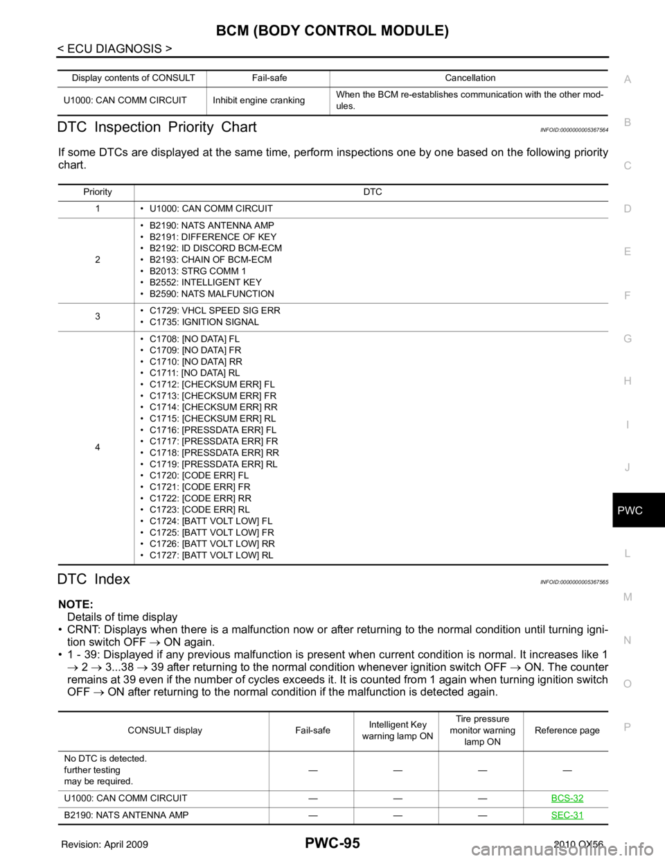
DTC Inspection Priority ChartINFOID:0000000005367564
If some DTCs are displayed at the same time, perform inspections one by one based on the following priority
chart.
DTC IndexINFOID:0000000005367565
NOTE: Details of time display
• CRNT: Displays when there is a malfunction now or after returning to the normal condition until turning igni- tion switch OFF → ON again.
• 1 - 39: Displayed if any previous ma lfunction is present when current conditi on is normal. It increases like 1
→ 2 → 3...38 → 39 after returning to the normal condition whenever ignition switch OFF → ON. The counter
remains at 39 even if the number of cycles exceeds it. It is counted from 1 again when turning ignition switch
OFF → ON after returning to the normal condi tion if the malfunction is detected again.
Display contents of CONSULT Fail-safe Cancellation
U1000: CAN COMM CIRCUIT I nhibit engine crankingWhen the BCM re-establishes communication with the other mod-
ules.
Priority
DTC
1 • U1000: CAN COMM CIRCUIT
2 • B2190: NATS ANTENNA AMP
• B2191: DIFFERENCE OF KEY
• B2192: ID DISCORD BCM-ECM
• B2193: CHAIN OF BCM-ECM
• B2013: STRG COMM 1
• B2552: INTELLIGENT KEY
• B2590: NATS MALFUNCTION
3 • C1729: VHCL SPEED SIG ERR
• C1735: IGNITION SIGNAL
4 • C1708: [NO DATA] FL
• C1709: [NO DATA] FR
• C1710: [NO DATA] RR
• C1711: [NO DATA] RL
• C1712: [CHECKSUM ERR] FL
• C1713: [CHECKSUM ERR] FR
• C1714: [CHECKSUM ERR] RR
• C1715: [CHECKSUM ERR] RL
• C1716: [PRESSDATA ERR] FL
• C1717: [PRESSDATA ERR] FR
• C1718: [PRESSDATA ERR] RR
• C1719: [PRESSDATA ERR] RL
• C1720: [CODE ERR] FL
• C1721: [CODE ERR] FR
• C1722: [CODE ERR] RR
• C1723: [CODE ERR] RL
• C1724: [BATT VOLT LOW] FL
• C1725: [BATT VOLT LOW] FR
• C1726: [BATT VOLT LOW] RR
• C1727: [BATT VOLT LOW] RL
CONSULT display
Fail-safeIntelligent Key
warning lamp ON Tire pressure
monitor warning lamp ON Reference page
No DTC is detected.
further testing
may be required. ————
U1000: CAN COMM CIRCUIT ———BCS-32
B2190: NATS ANTENNA AMP ———SEC-31
Revision: April 20092010 QX56