2010 INFINITI QX56 oil pressure
[x] Cancel search: oil pressurePage 2332 of 4210
HA-40
< ON-VEHICLE REPAIR >
HIGH-PRESSURE FLEXIBLE HOSE
HIGH-PRESSURE FLEXIBLE HOSE
Removal and Installation for High-Pressure Flexible HoseINFOID:0000000005147659
REMOVAL
1. Remove the engine under cover.
2. Remove the front LH fender protector. Refer to EXT-23, "
Removal and Installation".
3. Remove the engine air cleaner and air ducts. Refer to EM-25, "
Removal and Installation".
4. Discharge the refrigerant. Refer to HA-20, "
HFC-134a (R-134a) Service Procedure".
5. Remove the high-pressure flexible hose. CAUTION:
Cap or wrap the joint of the pipe with suitable mate rial such as vinyl tape to avoid the entry of air.
INSTALLATION
Installation is in the reverse order of removal.
Refer to HA-29, "
Component".
CAUTION:
• Replace the O-ring of the high-pressure flexible hose with a new one, then apply compressor oil to it
when installing it.
• After charging refrigerant, check for leaks.
Revision: April 20092010 QX56
Page 2333 of 4210
HIGH-PRESSURE PIPEHA-41
< ON-VEHICLE REPAIR >
C
DE
F
G H
J
K L
M A
B
HA
N
O P
HIGH-PRESSURE PIPE
Removal and Installation for High-Pressure PipeINFOID:0000000005147660
REMOVAL
1. Remove the cowl top extension. Refer to EXT-18, "Removal and Installation".
2. Disconnect the battery negative terminal and positive battery terminal.
3. Reposition the IPDM E/R aside.
4. Remove the front right wheel and tire assembly. Refer to WT-49, "
Rotation".
5. Position aside the front floor insulator.
6. Discharge the refrigerant. Refer to HA-20, "
HFC-134a (R-134a) Service Procedure".
7. Remove the low pressure pipe. Refer to HA-37, "
Removal and Installation for Low-Pressure Pipe".
8. Remove the high-pressure pipe. CAUTION:
Cap or wrap the joint of the pipe with suitable mate rial such as vinyl tape to avoid the entry of air.
INSTALLATION
Installation is in the reverse order of removal.
Refer to HA-29, "
Component".
CAUTION:
• Replace the O-ring of the high-pressure pipe with a new one, then apply compressor oil to it when
installing it.
• After charging refrigerant, check for leaks.
Removal and Installation for Rear High- and Low-Pressure A/C and Heater Core Pipes
INFOID:0000000005147661
REMOVAL
1. Discharge the refrigerant from the A/C system. Refer to HA-20, "HFC-134a (R-134a) Service Procedure".
2. Drain the coolant from the engine cooling system. Refer to CO-11, "
Changing Engine Coolant".
3. Disconnect the underfloor rear heater hoses (1 and 2) from the rear heater pipes underneath the vehicle.
• : Front
4. Remove the rear high- and low-pressure pipes bolt (A) to dis- connect the rear high- and low-pressure pipes from the under-
floor rear high- and low-pressure pipes underneath the vehicle.
CAUTION:
Cap or wrap the joint of the pipes with suitable material
such as vinyl tape to avo id the entry of air.
5. Remove the rear high- and low-pressure pipes nuts (B).
NOTE:
The remaining steps are performed inside the rear luggage area of the vehicle.
6. Remove the luggage side finisher lower RH. Refer to INT-19, "
Removal and Installation".
7. Disconnect the rear heater core hoses (1 and 2) from the rear heater core (3).
• : Front
ALIIA0216ZZ
ALIIA0218ZZ
Revision: April 20092010 QX56
Page 2334 of 4210
HA-42
< ON-VEHICLE REPAIR >
HIGH-PRESSURE PIPE
8. Remove the rear high- and low-pressure pipes bracket bolt (A)to release the bracket.
• Rear blower motor (1)
• : Front
9. Remove the rear high- and low-pressure pipes bolt (A) to dis- connect the rear high- and low-pressure pipes from the rear
expansion valve (1).
• : Front
CAUTION:
Cap or wrap the joint of the pipes with suitable material
such as vinyl tape to avoid the entry of air.
10. Disconnect the following electrical connectors: • Rear air mix door motor (1)
• Rear variable blower control (2)
• Rear blower motor (3)
• : Front
11. Disconnect the ducts from the rear heater and cooling unit assembly. Refer to HA-29, "
Component".
12. Remove the rear heater and cooling unit assembly. CAUTION:
Cap or wrap the joint of the pipes with suitable material such as viny l tape to avoid the entry of air.
13. Remove the rear high- and low-pressure A/C pipes.
INSTALLATION
Installation is in the reverse order of removal.
Refer to HA-29, "
Component".
CAUTION:
• Replace the O-rings on the rear high- and low-pr essure A/C pipes with a new ones, then apply com-
pressor oil to them for installation.
• After charging the refrigerant, check for leaks.
Removal and Installati on for Underfloor Rear High- and Low-Pressure A/C and Heater
Core Pipes
INFOID:0000000005147662
REMOVAL
1. Drain the engine coolant. Refer to CO-11, "Changing Engine Coolant".
2. Disconnect the battery negative terminal.
3. Disconnect the generator harness.
4. Discharge the refrigerant. Refer to HA-20, "
HFC-134a (R-134a) Service Procedure".
ALIIA0219ZZ
ALIIA0220ZZ
ALIIA0221ZZ
Revision: April 20092010 QX56
Page 2335 of 4210
HIGH-PRESSURE PIPEHA-43
< ON-VEHICLE REPAIR >
C
DE
F
G H
J
K L
M A
B
HA
N
O P
5. Remove the front and rear bumper fascia. Refer to EXT-13, "Removal and Installation" (front), EXT-15,
"Removal and Installation" (rear).
6. Reposition the front fender protector out of the way. Refer to EXT-23, "
Removal and Installation".
7. Disconnect the chassis harness connector.
8. Remove the spare wheel and tire.
9. Remove the tailpipe and tailpipe hanger bracket. Refer to EX-6, "
Removal and Installation".
10. Remove the seatbelt latch anchor. Refer to EX-6, "
Removal and Installation".
11. Remove the front floor heat shield.
12. Disconnect each end of the underfloor rear high- and low-pressure A/C and heater core pipes. Refer to HA-29, "
Component".
CAUTION:
Cap or wrap the joint of the pipes with suitable material such as viny l tape to avoid the entry of air.
13. Set two suitable jacks at the RH body mount points to support the vehicle body when it is separated from the RH side of the frame.
14. Remove the RH body mount bolts. Refer to BRM-6, "
Body Mounting".
15. Use the vehicle hoist to lower the RH side of the frame from the RH side of the body [approximately 305 mm (12 in)] until there is sufficient clearance to remove the underfloor rear high- and low-pressure A/C
and heater core pipes from between the body and the frame.
16. Remove the underfloor rear high- and low-pressure A/C and heater core pipes from the back of the vehi- cle.
INSTALLATION
Installation is in the reverse order of removal.
CAUTION:
• Replace the O-rings of the underfloor rear high - and low-pressure A/C and heater core pipes with
new ones, then apply compressor oil to them for installation.
• After charging refrigerant, check for leaks.
Revision: April 20092010 QX56
Page 2336 of 4210
HA-44
< ON-VEHICLE REPAIR >
CONDENSER
CONDENSER
Removal and Installation for CondenserINFOID:0000000005147663
REMOVAL
1. Discharge the refrigerant. Refer to HA-20, "HFC-134a (R-134a) Service Procedure".
2. Remove the radiator. Refer to CO-15, "
Removal and Installation".
CAUTION:
Be careful not to damage the core su rface of the condenser and the radiator.
3. Disconnect the high-pressure flexible hose and the high-pressure pipe from the condenser. CAUTION:
Cap or wrap the joint of the pipe with suitable ma terial such as vinyl tape to avoid the entry of air.
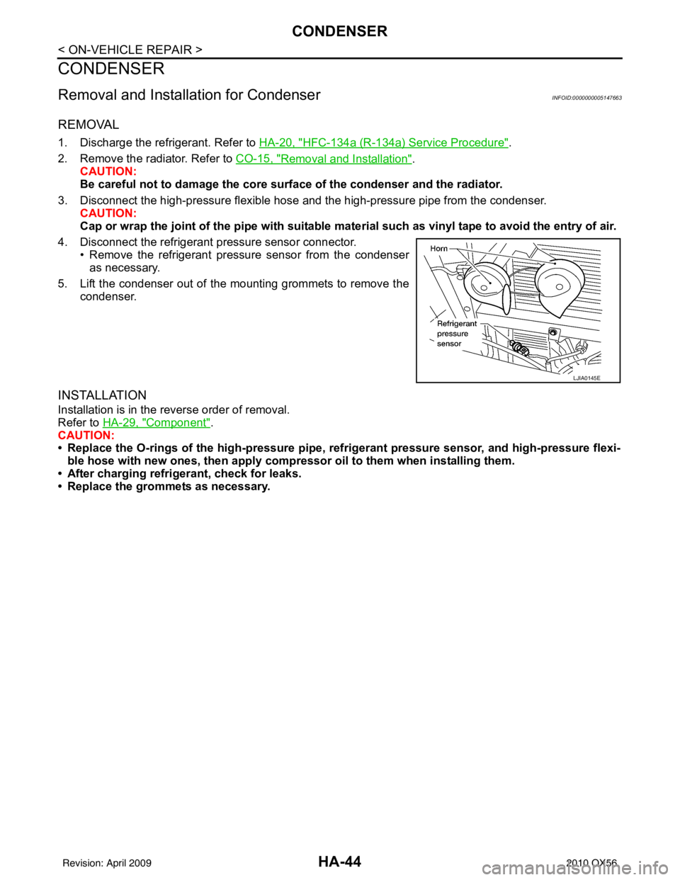
4. Disconnect the refrigerant pressure sensor connector. • Remove the refrigerant pressure sensor from the condenseras necessary.
5. Lift the condenser out of the mounting grommets to remove the condenser.
INSTALLATION
Installation is in the reverse order of removal.
Refer to HA-29, "
Component".
CAUTION:
• Replace the O-rings of the high-pressure pipe, refrigerant pressure sensor, and high-pressure flexi- ble hose with new ones, then apply compr essor oil to them when installing them.
• After charging refrigerant, check for leaks.
• Replace the grommets as necessary.
LJIA0145E
Revision: April 20092010 QX56
Page 2338 of 4210
HA-46
< ON-VEHICLE REPAIR >
REFRIGERANT PRESSURE SENSOR
REFRIGERANT PRESSURE SENSOR
Removal and Installation for Refrigerant Pressure SensorINFOID:0000000005147665
REMOVAL
1. Discharge the refrigerant. Refer to HA-20, "HFC-134a (R-134a) Service Procedure".
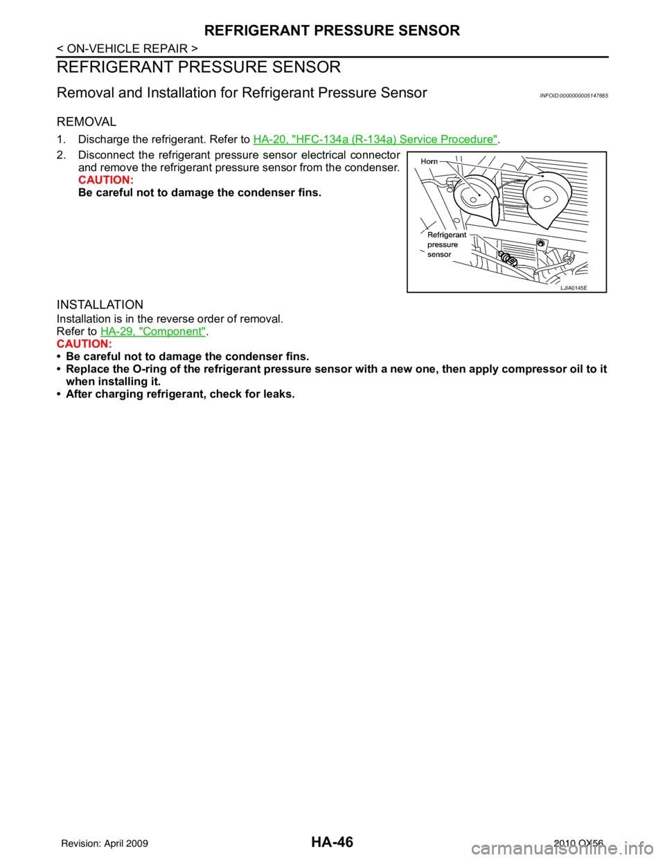
2. Disconnect the refrigerant pressure sensor electrical connector and remove the refrigerant pressure sensor from the condenser.
CAUTION:
Be careful not to damage the condenser fins.
INSTALLATION
Installation is in the reverse order of removal.
Refer to HA-29, "
Component".
CAUTION:
• Be careful not to damage the condenser fins.
• Replace the O-ring of the refriger ant pressure sensor with a new one, then apply compressor oil to it
when installing it.
• After charging refrigerant, check for leaks.
LJIA0145E
Revision: April 20092010 QX56
Page 2351 of 4210
![INFINITI QX56 2010 Factory Service Manual REFRIGERATION SYSTEMHAC-11
< FUNCTION DIAGNOSIS > [AUTOMATIC AIR CONDITIONER]
C
D
E
F
G H
J
K L
M A
B
HAC
N
O P
REFRIGERATION SYSTEM
Refrigerant CycleINFOID:0000000005197357
REFRIGERANT FLOW
The refri INFINITI QX56 2010 Factory Service Manual REFRIGERATION SYSTEMHAC-11
< FUNCTION DIAGNOSIS > [AUTOMATIC AIR CONDITIONER]
C
D
E
F
G H
J
K L
M A
B
HAC
N
O P
REFRIGERATION SYSTEM
Refrigerant CycleINFOID:0000000005197357
REFRIGERANT FLOW
The refri](/manual-img/42/57032/w960_57032-2350.png)
REFRIGERATION SYSTEMHAC-11
< FUNCTION DIAGNOSIS > [AUTOMATIC AIR CONDITIONER]
C
D
E
F
G H
J
K L
M A
B
HAC
N
O P
REFRIGERATION SYSTEM
Refrigerant CycleINFOID:0000000005197357
REFRIGERANT FLOW
The refrigerant flows in the standard pattern, that is, through the compressor, the condenser with liquid tank,
through the front and rear evaporators, and back to the compressor. The refrigerant evaporation through the
evaporator coils are controlled by front and rear externally equalized expansion valves, located inside the front
and rear evaporator cases.
Refrigerant System ProtectionINFOID:0000000005197358
REFRIGERANT PRESSURE SENSOR
The refrigerant system is protected against excessively hi gh or low pressures by the refrigerant pressure sen-
sor, located on the condenser. If the system pressure rises above or falls below the specifications, the refriger-
ant pressure sensor detects the pressure inside the refrigerant line and sends a voltage signal to the ECM.
The ECM de-energizes the A/C relay to disengage the magnetic compressor clutch when pressure on the high
pressure side detected by refrigerant pressu re sensor is over about 2,746 kPa (28 kg/cm
2, 398 psi), or below
about 120 kPa (1.22 kg/cm
2, 17.4 psi).
WJIA1342E
Revision: April 20092010 QX56
Page 2453 of 4210
![INFINITI QX56 2010 Factory Service Manual INSUFFICIENT COOLINGHAC-113
< SYMPTOM DIAGNOSIS > [AUTOMATIC AIR CONDITIONER]
C
D
E
F
G H
J
K L
M A
B
HAC
N
O P
dard (usual) pressure, however, differs from vehicle to vehicle, refer to above table (A INFINITI QX56 2010 Factory Service Manual INSUFFICIENT COOLINGHAC-113
< SYMPTOM DIAGNOSIS > [AUTOMATIC AIR CONDITIONER]
C
D
E
F
G H
J
K L
M A
B
HAC
N
O P
dard (usual) pressure, however, differs from vehicle to vehicle, refer to above table (A](/manual-img/42/57032/w960_57032-2452.png)
INSUFFICIENT COOLINGHAC-113
< SYMPTOM DIAGNOSIS > [AUTOMATIC AIR CONDITIONER]
C
D
E
F
G H
J
K L
M A
B
HAC
N
O P
dard (usual) pressure, however, differs from vehicle to vehicle, refer to above table (Ambient air temperature-
to-operating pressure table).
Both High- and Low-pressure Sides are Too High
High-pressure Side is Too High and Low-pressure Side is Too Low
High-pressure Side is Too Low and Low-pressure Side is Too High
Gauge indication Refrigerant cycleProbable causeCorrective action
Both high- and low-pressure sides
are too high. Pressure is reduced soon af-
ter water is splashed on con-
denser.
Excessive refrigerant charge in
refrigeration cycle
Reduce refrigerant until speci-
fied pressure is obtained.
Air suction by cooling fan is in-
sufficient. Insufficient condenser cooling
performance
↓
1. Condenser fins are
clogged.
2. Improper fan rotation of
cooling fan • Clean condenser.
• Check and repair cooling fan
if necessary.
• Low-pressure pipe is not cold.
• When compressor is
stopped high-pressure val-
ue quickly drops by approx-
imately 196 kPa (2 kg/cm
2 ,
28 psi). It then decreases
gradually thereafter. Poor heat exchange in con-
denser
(After compressor operation
stops, high-pressure decreas-
es too slowly.)
↓
Air in refrigeration cycle
Evacuate and recharge system.
Engine tends to overheat. Engine cooling systems mal-
function. Check and repair engine cool-
ing system.
• An area of the low-pressure pipe is colder than areas
near the evaporator outlet.
• Plates are sometimes cov- ered with frost. • Excessive liquid refrigerant
on low-pressure side
• Excessive refrigerant dis-
charge flow
• Expansion valve is open a lit- tle compared with the speci-
fication.
↓
Improper expansion valve ad-
justment Replace expansion valve.
AC359A
Gauge indication
Refrigerant cycleProbable causeCorrective action
High-pressure side is too high and
low-pressure side is too low. Upper side of condenser and
high-pressure side are hot,
however, liquid tank is not so
hot.High-pressure tube or parts lo-
cated between compressor
and condenser are clogged or
crushed.
• Check and repair or replace
malfunctioning parts.
• Check oil for contamination.
AC360A
Revision: April 20092010 QX56