2010 INFINITI QX56 battery
[x] Cancel search: batteryPage 3256 of 4210
SCS-24
< COMPONENT DIAGNOSIS >
EXHAUST VALVE SOLENOID CIRCUIT
EXHAUST VALVE SOLENOID CIRCUIT
DescriptionINFOID:0000000005148184
Receives exhaust valve solenoid signal from suspension control unit. When activated, the exhaust valve sole-
noid releases air pressure from the suspension control system.
Component Function CheckINFOID:0000000005148185
1.CHECK EXHAUST SOLENOID OPERATION
CAUTION:
While operating this active test, the suspension control system will vent air pressure and the vehicle
ride height will lower. Ensure th e area around the vehicle is free fr om obstructions before beginning
test.
CONSULT-III
1. Ensure the suspension control system has air pressure and is not drooping in the rear.
2. Select "EXHAUST SOLENOID" of AIR LEVELIZER active test items.
3. While operating test item, check that the exhaust valve solenoid opens to vent air from the system. The vehicle should lower when the exhaust valve solenoid is activated.
Does the system vent properly?
YES >> Exhaust valve solenoid is operating normally.
NO >> Refer to SCS-24, "
Diagnosis Procedure".
Diagnosis ProcedureINFOID:0000000005148186
Regarding Wiring Diagram information, refer to SCS-29, "Wiring Diagram".
1.CHECK EXHAUST VALVE SOLENOID SIGNAL
CONSULT-III
1. Connect suspension control unit connector B3.
2. Turn ignition switch ON.
3. Select "EXHAUST SOLENOID" of AIR LEVELIZER active test
items.
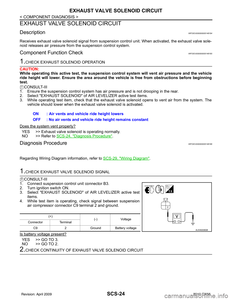
4. While test item is operating, check signal between suspension
air compressor connector C9 terminal 2 and ground.
Is battery voltage present?
YES >> GO TO 3.
NO >> GO TO 2.
2.CHECK CONTINUITY OF EXHA UST VALVE SOLENOID CIRCUIT
ON : Air vents and vehicle ride height lowers
OFF : No air vents and vehicle ride height remains constant
(+)
(-)Voltage
Connector Terminal
C9 2Ground Battery voltage
ALEIA0036GB
Revision: April 20092010 QX56
Page 3260 of 4210

SCS-28
< ECU DIAGNOSIS >
SUSPENSION CONTROL UNIT
ECU DIAGNOSIS
SUSPENSION CONTROL UNIT
Reference ValueINFOID:0000000005148190
TERMINAL LAYOUT
PHYSICAL VALUES
AWLIA1640ZZ
Terminal
(Wire color) Description
ConditionReference value
(Approx.)
+ – Signal nameInput/
Output
1
(V) Ground Compressor relay output Output Ignition
switch ON Air levelizer raising vehicle
ride height
Battery voltage
3
(W) Ground Height sensor input
InputIgnition
switch
ON —0
.2 V - 4 .8 V
5
(R) Ground VREF output (height sen-
sor)
OutputIgnition
switch ON —5
V
6
(G/R) Ground IGN power supply
InputIgnition
switch ON or
START —
Battery voltage
7
(W/L) Ground BAT power supply
InputIgnition
switch OFF —
Battery voltage
8
(G/W) Ground Diagnostic K-line Input/
Output ——
—
9
(SB) Ground Exhaust valve output Output Ignition
switch ON Air levelizer lowering vehi-
cle ride height (venting)
Battery voltage
10
(BR) Ground Warning lamp output Output Ignition
switch
ON Warning lamp ON
0V
Warning lamp OFF Battery voltage
14
(L) Ground Height sensor ground Output Ignition
switch ON —
Less than 0.2V
15
(BR/W) Ground Generator input
InputIgnition
switch ON Charge light ON
0V
Charge light OFF Battery voltage
16
(B) Ground
Suspension control unit
ground InputIgnition
switch
ON —
Less than 0.2V
Revision: April 20092010 QX56
Page 3272 of 4210
SCS-40
< PRECAUTION >
PRECAUTIONS
PRECAUTION
PRECAUTIONS
Precaution for Supplemental Restraint System (SRS) "AIR BAG" and "SEAT BELT
PRE-TENSIONER"
INFOID:0000000005383225
The Supplemental Restraint System such as “A IR BAG” and “SEAT BELT PRE-TENSIONER”, used along
with a front seat belt, helps to reduce the risk or severity of injury to the driver and front passenger for certain
types of collision. This system includes seat belt switch inputs and dual stage front air bag modules. The SRS
system uses the seat belt switches to determine the front air bag deployment, and may only deploy one front
air bag, depending on the severity of a collision and w hether the front occupants are belted or unbelted.
Information necessary to service the system safely is included in the SR and SB section of this Service Man-
ual.
WARNING:
• To avoid rendering the SRS inopera tive, which could increase the risk of personal injury or death in
the event of a collision which would result in air bag inflation, all maintenance must be performed by
an authorized NISSAN/INFINITI dealer.
• Improper maintenance, including in correct removal and installation of the SRS, can lead to personal
injury caused by unintent ional activation of the system. For re moval of Spiral Cable and Air Bag
Module, see the SR section.
• Do not use electrical test equipmen t on any circuit related to the SRS unless instructed to in this
Service Manual. SRS wiring harn esses can be identified by yellow and/or orange harnesses or har-
ness connectors.
PRECAUTIONS WHEN USING POWER TOOLS (AIR OR ELECTRIC) AND HAMMERS
WARNING:
• When working near the Airbag Diagnosis Sensor Unit or other Airbag System sensors with the Igni-
tion ON or engine running, DO NOT use air or electri c power tools or strike near the sensor(s) with a
hammer. Heavy vibration could activate the sensor( s) and deploy the air bag(s), possibly causing
serious injury.
• When using air or electric power tools or hammers , always switch the Ignition OFF, disconnect the
battery, and wait at least 3 minu tes before performing any service.
Precaution for Rear SuspensionINFOID:0000000005148201
• When installing the rubber bushings, the final ti ghtening must be done under unladen condition and with the
tires on level ground. Oil will shorten the life of the r ubber bushings, so wipe off any spilled oil immediately.
• Unladen condition means the fuel tank, engine coolant and lubricants are at the full specification. The spare tire, jack, hand tools, and mats are in their designated positions.
• After installing suspension components, check the wheel alignment.
• Caulking nuts are not reusable. Always use new caulking nuts for installation. New caulking nuts are pre-
oiled, do not apply any additional lubrication.
Revision: April 20092010 QX56
Page 3274 of 4210

SE-2
Precaution Necessary for Steering Wheel Rota-
tion After Battery Disconnect ..................................
45
Precaution for Work ................................................46
PREPARATION ...........................................47
PREPARATION .............................................. ...47
Special Service Tool ............................................ ...47
Commercial Service Tool .......................................47
ON-VEHICLE REPAIR ................................48
FRONT SEAT ................................................. ...48
Exploded View ..................................................... ...48
Removal and Installation ........................................51
SECOND SEAT .................................................52
Exploded View ..................................................... ...52
Removal and Installation ........................................56
THIRD SEAT ......................................................57
Exploded View ..................................................... ...57
LH Side Seat ...........................................................59
Power seat cross beam ..........................................60
RH Side Seat ..........................................................64
DISASSEMBLY AND ASSEMBLY ............66
FRONT SEAT ................................................. ...66
Exploded View ..................................................... ...66
Disassembly and Assembly ....................................69
SECOND SEAT .................................................72
Disassembly and Assembly ................................. ...72
THIRD SEAT ......................................................77
Exploded View ..................................................... ...77
Revision: April 20092010 QX56
Page 3291 of 4210
THIRD SEATSE-19
< COMPONENT DIAGNOSIS >
C
DE
F
G H
I
K L
M A
B
SE
N
O P
THIRD SEAT
Power Supply and Ground Circu it Check for Third Row Power Folding Seat Control
Unit
INFOID:0000000005147387
Regarding Wiring Diagram information, refer to SE-24, "Wiring Diagram".
1.CHECK FUSES AND FUSIBLE LINK
Check for blown fuses or fusible link.
Are any fuses or fusible links blown?
YES >> Install new fuse. Eliminate cause of malfunction if fuse blows again.
NO >> GO TO 2
2.POWER SUPPLY CIRCUIT CHECK
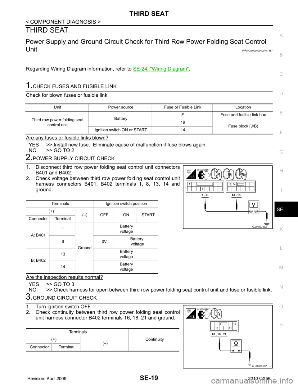
1. Disconnect third row power folding seat control unit connectors B401 and B402.
2. Check voltage between third row power folding seat control unit harness connectors B401, B402 terminals 1, 8, 13, 14 and
ground.
Are the inspection results normal?
YES >> GO TO 3
NO >> Check harness for open between third row power folding seat control unit and fuse or fusible link.
3.GROUND CIRCUIT CHECK
1. Turn ignition switch OFF.
2. Check continuity between third row power folding seat control unit harness connector B402 terminals 16, 18, 21 and ground.
Unit Power source Fuse or Fusible Link Location
Third row power folding seat control unit Battery
F
Fuse and fusible link box
19 Fuse block (J/B)
Ignition switch ON or START 14
TerminalsIgnition switch position
(+) (–) OFF ON START
Connector Terminal
A: B401 1
Ground Battery
voltage
80 VBattery
voltage
B: B402 13
Battery
voltage
14 Battery
voltage
ALJIA0274ZZ
Te r m i n a l s
Continuity
(+)
(–)
Connector Terminal
ALJIA0275ZZ
Revision: April 20092010 QX56
Page 3292 of 4210
SE-20
< COMPONENT DIAGNOSIS >
THIRD SEAT
Do all terminals have ground?
YES >> Inspection End.
NO >> Check harness for ground.
Third Row Power Folding Seat SwitchINFOID:0000000005147388
1.CHECK THIRD ROW POWER FOLDING SEAT SWITCH OPERATION
1. Turn ignition switch OFF.
2. Disconnect third row power folding seat switch.
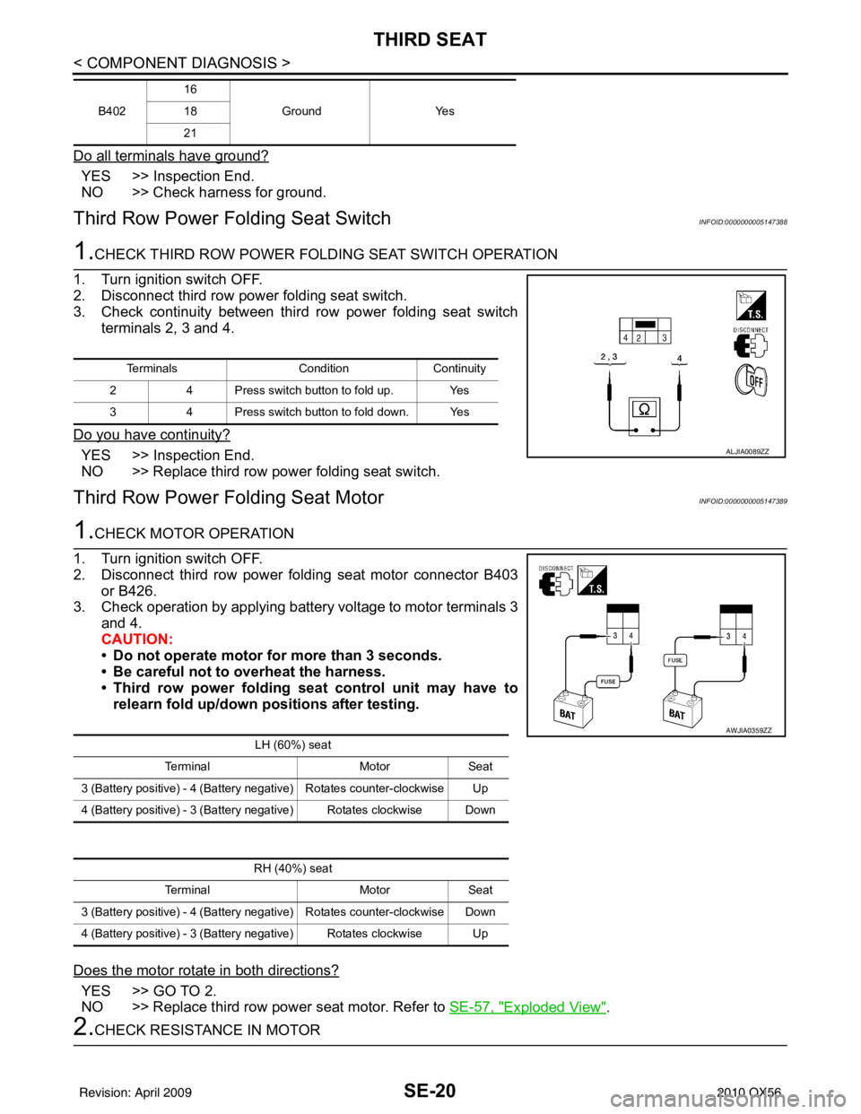
3. Check continuity between third row power folding seat switch terminals 2, 3 and 4.
Do you have continuity?
YES >> Inspection End.
NO >> Replace third row power folding seat switch.
Third Row Power Folding Seat MotorINFOID:0000000005147389
1.CHECK MOTOR OPERATION
1. Turn ignition switch OFF.
2. Disconnect third row power folding seat motor connector B403 or B426.
3. Check operation by applying battery voltage to motor terminals 3
and 4.
CAUTION:
• Do not operate motor for more than 3 seconds.
• Be careful not to overheat the harness.
• Third row power folding seat control unit may have to
relearn fold up/down positions after testing.
Does the motor rotate in both directions?
YES >> GO TO 2.
NO >> Replace third row power seat motor. Refer to SE-57, "
Exploded View".
2.CHECK RESISTANCE IN MOTOR
B40216
Ground Yes
18
21
Terminals Condition Continuity
2 4 Press switch button to fold up. Yes
3 4 Press switch button to fold down. Yes
ALJIA0089ZZ
LH (60%) seat
Terminal MotorSeat
3 (Battery positive) - 4 (Battery negative) Rotates counter-clockwise Up
4 (Battery positive) - 3 (Battery negative) Rotates clockwise Down
AWJIA0359ZZ
RH (40%) seat
Terminal MotorSeat
3 (Battery positive) - 4 (Battery negative) Rotates counter-clockwise Down
4 (Battery positive) - 3 (Battery negative) Rotates clockwise Up
Revision: April 20092010 QX56
Page 3294 of 4210
SE-22
< ECU DIAGNOSIS >
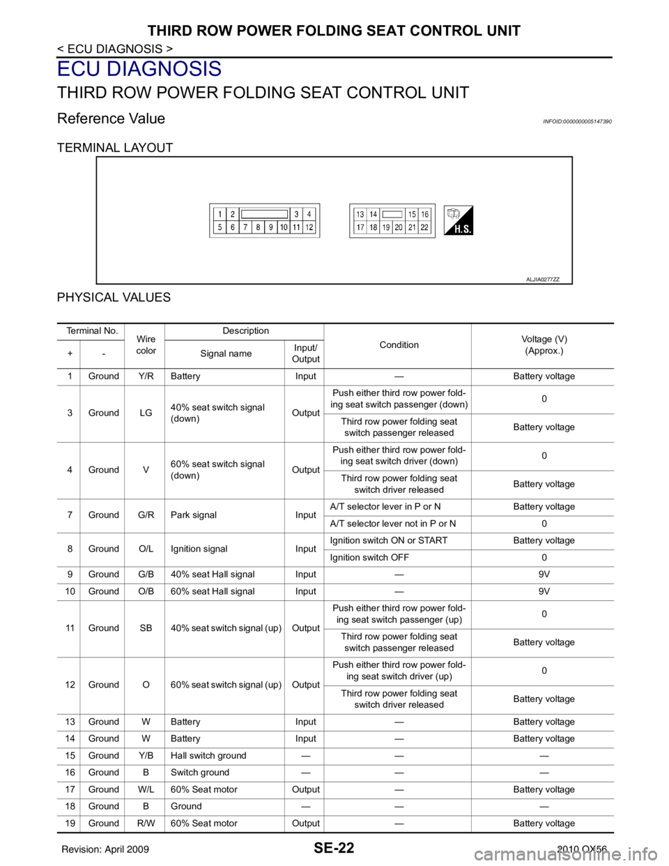
THIRD ROW POWER FOLDING SEAT CONTROL UNIT
ECU DIAGNOSIS
THIRD ROW POWER FOLDING SEAT CONTROL UNIT
Reference ValueINFOID:0000000005147390
TERMINAL LAYOUT
PHYSICAL VALUES
ALJIA0277ZZ
Te r m i n a l N o .Wire
color Description
ConditionVoltage (V)
(Approx.)
+ - Signal nameInput/
Output
1 Ground Y/R Battery Input— Battery voltage
3Ground LG 40% seat switch signal
(down) OutputPush either third row power fold-
ing seat switch passenger (down) 0
Third row power folding seat switch passenger released Battery voltage
4Ground V 60% seat switch signal
(down) OutputPush either third row power fold-
ing seat switch driver (down) 0
Third row power folding seat switch driver released Battery voltage
7 Ground G/R Park signal InputA/T selector lever in P or N
Battery voltage
A/T selector lever not in P or N 0
8 Ground O/L Ignition signal InputIgnition switch ON or START
Battery voltage
Ignition switch OFF 0
9 Ground G/B 40% seat Hall signal Input —9V
10 Ground O/B 60% seat Hall signal Input —9V
11 Ground SB 40% seat switch signal (up) Output Push either third row power fold-
ing seat switch passenger (up) 0
Third row power folding seat switch passenger released Battery voltage
12 Ground O 60% seat switch signal (up) Output Push either third row power fold-
ing seat switch driver (up) 0
Third row power folding seat switch driver released Battery voltage
13 Ground W Battery Input— Battery voltage
14 Ground W Battery Input— Battery voltage
15 Ground Y/B Hall switch ground —— —
16 Ground B Switch ground —— —
17 Ground W/L 60% Seat motor Output— Battery voltage
18 Ground B Ground —— —
19 Ground R/W 60% Seat motor Output— Battery voltage
Revision: April 20092010 QX56
Page 3295 of 4210

THIRD ROW POWER FOLDING SEAT CONTROL UNITSE-23
< ECU DIAGNOSIS >
C
DE
F
G H
I
K L
M A
B
SE
N
O P
20 Ground G/W 40% Seat motor Output— Battery voltage
21 Ground B Ground —— —
22 Ground V 40% Seat motor Output— Battery voltage
Te r m i n a l N o .
Wire
color Description
ConditionVoltage (V)
(Approx.)
+ - Signal nameInput/
Output
Revision: April 20092010 QX56