2010 INFINITI QX56 battery
[x] Cancel search: batteryPage 3220 of 4210
PRECAUTIONSSB-3
< PRECAUTION >
C
DE
F
G
I
J
K L
M A
B
SB
N
O P
should be replaced even if the seat belts are not in use during a frontal collision in which the air bags
are deployed.
Replace any seat belt assembly (including anchor bolts) if:
• The seat belt was in use at the time of a collision (except for minor collisions and the belts, retractors and
buckles show no damage and continue to operate properly).
• The seat belt was damaged in an accident. (i.e., torn webbing, bent retractor or guide, etc.)
• The seat belt attaching point was damaged in an accident. Inspect the seat belt attaching area for damage
or distortion and repair as necessary before installing a new seat belt assembly.
• Anchor bolts are deformed or worn out.
• The seat belt pre-tensioner should be replaced even if t he seat belts are not in use during the collision in
which the air bags are deployed.
OCCUPANT CLASSIFICATION SYSTEM
• Replace occupant classification system control uni t and passenger front seat cushion as an assembly.
Refer to SE-51, "
Removal and Installation".
Precaution Necessary for Steering Wheel Rotation After Battery Disconnect
INFOID:0000000005266527
NOTE:
• This Procedure is applied only to models with Intelligent Key system and NATS (NISSAN ANTI-THEFT SYS-
TEM).
• Remove and install all control units after disconnecti ng both battery cables with the ignition knob in the
″ LOCK ″ position.
• Always use CONSULT-III to perform self-diagnosis as a part of each function inspection after finishing work.
If DTC is detected, perform trouble diagnosis according to self-diagnostic results.
For models equipped with the Intelligent Key system and NATS , an electrically controlled steering lock mech-
anism is adopted on the key cylinder.
For this reason, if the battery is disconnected or if the battery is discharged, the steering wheel will lock and
steering wheel rotation will become impossible.
If steering wheel rotation is required when battery power is interrupted, follow the procedure below before
starting the repair operation.
OPERATION PROCEDURE
1. Connect both battery cables.
NOTE:
Supply power using jumper cables if battery is discharged.
2. Use the Intelligent Key or mechanical key to turn the ignition switch to the ″ACC ″ position. At this time, the
steering lock will be released.
3. Disconnect both battery cables. The steering lock will remain released and the steering wheel can be
rotated.
4. Perform the necessary repair operation.
5. When the repair work is completed, return the ignition switch to the ″LOCK ″ position before connecting
the battery cables. (At this time, the steering lock mechanism will engage.)
6. Perform a self-diagnosis check of al l control units using CONSULT-III.
Revision: April 20092010 QX56
Page 3222 of 4210
SEAT BELTSSB-5
< ON-VEHICLE REPAIR >
C
DE
F
G
I
J
K L
M A
B
SB
N
O P
• Before servicing SRS, turn the igni tion switch off, disconnect both battery terminals and wait at least
three minutes.
1. Disconnect both battery terminals, t hen wait at least three minutes.
2. Remove the center pillar lower finisher. Refer to INT-14, "
Removal and Installation".
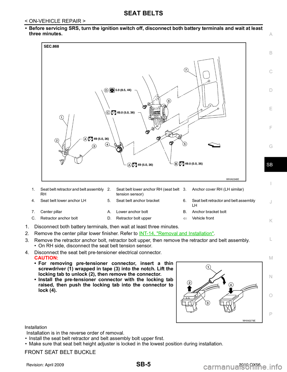
3. Remove the retractor anchor bolt, retractor bolt upper, then remove the retractor and belt assembly. • On RH side, disconnect the seat belt tension sensor.
4. Disconnect the seat belt pre-tensioner electrical connector. CAUTION:
• For removing pre-tensioner connector, insert a thinscrewdriver (1) wrapped in tape (3) into the notch. Lift the
locking tab to unlock (2), then remove the connector.
• Install the pre-tensioner co nnector with the locking tab
raised, then push the locking tab into the connector to
lock (4).
Installation
Installation is in the reverse order of removal.
• Install the seat belt retractor and belt assembly bolt upper first.
• Make sure that seat belt height adjuster is lo cked in the lowest position during installation.
FRONT SEAT BELT BUCKLE
1. Seat belt retractor and belt assembly
RH 2. Seat belt lower anchor RH (seat belt
tension sensor) 3. Anchor cover RH (LH similar)
4. Seat belt lower anchor LH 5. Seat belt anchor bracket6. Seat belt retractor and belt assembly
LH
7. Center pillar A. Lower anchor boltB. Anchor bracket bolt
C. Retractor anchor bolt D. Retractor bolt upper ⇐Vehicle front
WHIA0346E
WHIA0279E
Revision: April 20092010 QX56
Page 3238 of 4210
SCS-6
< FUNCTION DIAGNOSIS >
SUSPENSION CONTROL SYSTEM
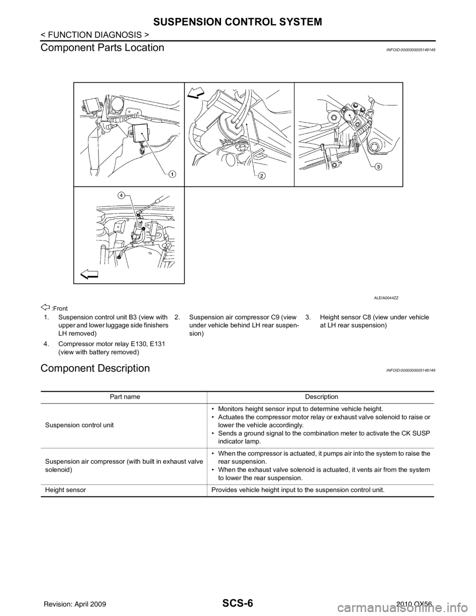
Component Parts Location
INFOID:0000000005148148
:Front
Component DescriptionINFOID:0000000005148149
1. Suspension control unit B3 (view with upper and lower luggage side finishers
LH removed) 2. Suspension air compressor C9 (view
under vehicle behind LH rear suspen-
sion) 3. Height sensor C8 (view under vehicle
at LH rear suspension)
4. Compressor motor relay E130, E131 (view with battery removed)
ALEIA0044ZZ
Part name Description
Suspension control unit • Monitors height sensor input to determine vehicle height.
• Actuates the compressor motor relay or exhaust valve solenoid to raise or
lower the vehicle accordingly.
• Sends a ground signal to the combination meter to activate the CK SUSP indicator lamp.
Suspension air compressor (with built in exhaust valve
solenoid) • When the compressor is actuated, it pumps air into the system to raise the
rear suspension.
• When the exhaust valve solenoid is actuated, it vents air from the system to lower the rear suspension.
Height sensor Provides vehicle height input to the suspension control unit.
Revision: April 20092010 QX56
Page 3249 of 4210
POWER SUPPLY AND GROUND CIRCUITSCS-17
< COMPONENT DIAGNOSIS >
C
DF
G H
I
J
K L
M A
B
SCS
N
O P
POWER SUPPLY AND GROUND CIRCUIT
SUSPENSION CONTROL UNIT
SUSPENSION CONTROL UNIT : Diagnosis ProcedureINFOID:0000000005148175
Regarding Wiring Diagram information, refer to SCS-29, "Wiring Diagram".
1.CHECK FUSES
Check that the following fuses of the sus pension control unit are not are not blown.
Are the fuses OK?
YES >> GO TO 2.
NO >> If fuse is blown, be sure to eliminate cause of malfunction before installing new fuse.
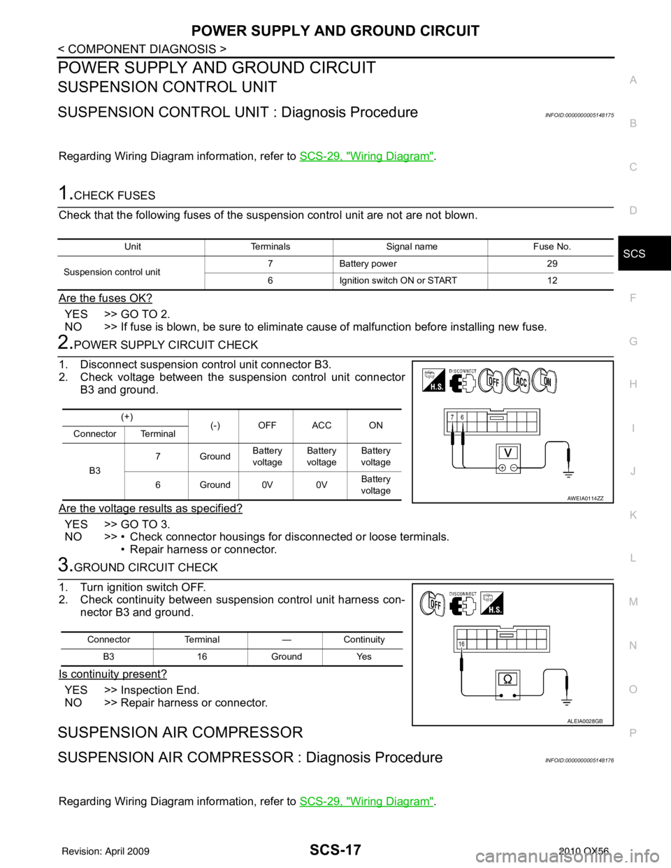
2.POWER SUPPLY CIRCUIT CHECK
1. Disconnect suspension control unit connector B3.
2. Check voltage between the suspension control unit connector B3 and ground.
Are the voltage results as specified?
YES >> GO TO 3.
NO >> • Check connector housings for disconnected or loose terminals. • Repair harness or connector.
3.GROUND CIRCUIT CHECK
1. Turn ignition switch OFF.
2. Check continuity between suspension control unit harness con- nector B3 and ground.
Is continuity present?
YES >> Inspection End.
NO >> Repair harness or connector.
SUSPENSION AIR COMPRESSOR
SUSPENSION AIR COMPRESSOR : Diagnosis ProcedureINFOID:0000000005148176
Regarding Wiring Diagram information, refer to SCS-29, "Wiring Diagram".
UnitTerminals Signal name Fuse No.
Suspension control unit 7
Battery power 29
6 Ignition switch ON or START 12
(+)
(-) OFF ACC ON
Connector Terminal
B3 7Ground
Battery
voltage Battery
voltage Battery
voltage
6Ground0V 0V Battery
voltage
AWEIA0114ZZ
Connector Terminal —Continuity
B3 16Ground Yes
ALEIA0028GB
Revision: April 20092010 QX56
Page 3250 of 4210
SCS-18
< COMPONENT DIAGNOSIS >
POWER SUPPLY AND GROUND CIRCUIT
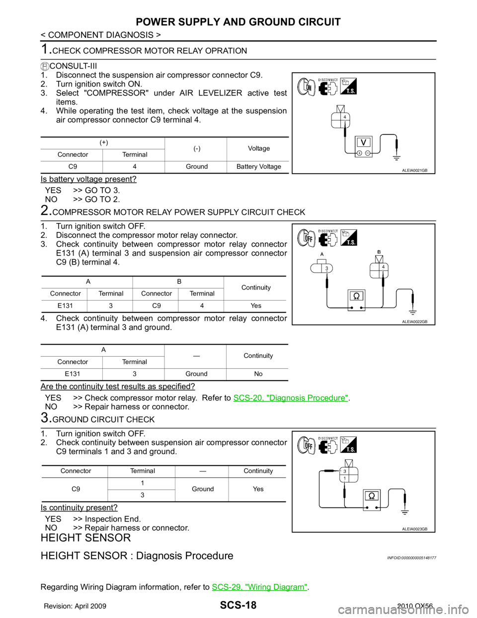
1.CHECK COMPRESSOR MOTOR RELAY OPRATION
CONSULT-III
1. Disconnect the suspension air compressor connector C9.
2. Turn ignition switch ON.
3. Select "COMPRESSOR" under AIR LEVELIZER active test items.
4. While operating the test item, check voltage at the suspension
air compressor connector C9 terminal 4.
Is battery voltage present?
YES >> GO TO 3.
NO >> GO TO 2.
2.COMPRESSOR MOTOR RELAY POWER SUPPLY CIRCUIT CHECK
1. Turn ignition switch OFF.
2. Disconnect the compressor motor relay connector.
3. Check continuity between compressor motor relay connector E131 (A) terminal 3 and suspension air compressor connector
C9 (B) terminal 4.
4. Check continuity between compressor motor relay connector E131 (A) terminal 3 and ground.
Are the continuity test results as specified?
YES >> Check compressor motor relay. Refer to SCS-20, "Diagnosis Procedure".
NO >> Repair harness or connector.
3.GROUND CIRCUIT CHECK
1. Turn ignition switch OFF.
2. Check continuity between suspension air compressor connector C9 terminals 1 and 3 and ground.
Is continuity present?
YES >> Inspection End.
NO >> Repair harness or connector.
HEIGHT SENSOR
HEIGHT SENSOR : Dia gnosis ProcedureINFOID:0000000005148177
Regarding Wiring Diagram information, refer to SCS-29, "Wiring Diagram".
(+)
(-)Voltage
Connector Terminal
C9 4Ground Battery Voltage
ALEIA0021GB
AB
Continuity
Connector Terminal Connector Terminal
E131 3 C9 4 Yes
A —Continuity
Connector Terminal
E131 3Ground No
ALEIA0022GB
Connector Terminal —Continuity
C9 1
Ground Yes
3
ALEIA0023GB
Revision: April 20092010 QX56
Page 3252 of 4210
SCS-20
< COMPONENT DIAGNOSIS >
COMPRESSOR MOTOR RELAY
COMPRESSOR MOTOR RELAY
DescriptionINFOID:0000000005148178
Receives suspension air compressor ON signal from suspension control unit. When activated, the compressor
motor relay supplies power to the suspension air compressor.
Component Function CheckINFOID:0000000005148179
1.CHECK COMPRESSOR MOTOR RELAY OPERATION
CAUTION:
The "COMPRESSOR" active test will remain ON until it is turned off using CONSULT-III. Allowing the
compressor to run for an extended period of time may cause damage to the suspension control sys-
tem components due to excessive air pressure.
CONSULT-III
1. Turn ignition ON.
2. Select "COMPRESSOR" of AIR LEVELIZER active test items.
3. While operating test item, check that the suspension air compressor turns ON.
Does the suspension air compressor operate properly?
YES >> Compressor motor relay and suspension air compressor are operating normally.
NO >> Refer to SCS-20, "
Diagnosis Procedure".
Diagnosis ProcedureINFOID:0000000005148180
Regarding Wiring Diagram information, refer to SCS-29, "Wiring Diagram".
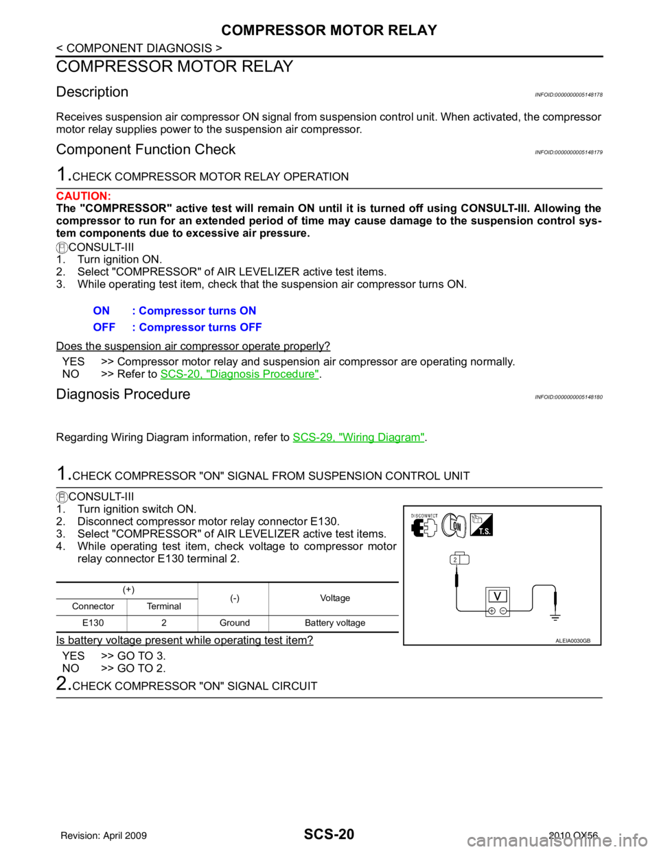
1.CHECK COMPRESSOR "ON" SIGNAL FROM SUSPENSION CONTROL UNIT
CONSULT-III
1. Turn ignition switch ON.
2. Disconnect compressor motor relay connector E130.
3. Select "COMPRESSOR" of AIR LEVELIZER active test items.
4. While operating test item, check voltage to compressor motor relay connector E130 terminal 2.
Is battery voltage present while operating test item?
YES >> GO TO 3.
NO >> GO TO 2.
2.CHECK COMPRESSOR "ON" SIGNAL CIRCUIT ON : Compressor turns ON
OFF : Compressor turns OFF
(+)
(-)Voltage
Connector Terminal
E130 2Ground Battery voltage
ALEIA0030GB
Revision: April 20092010 QX56
Page 3253 of 4210
COMPRESSOR MOTOR RELAYSCS-21
< COMPONENT DIAGNOSIS >
C
DF
G H
I
J
K L
M A
B
SCS
N
O P
1. Turn ignition switch OFF.
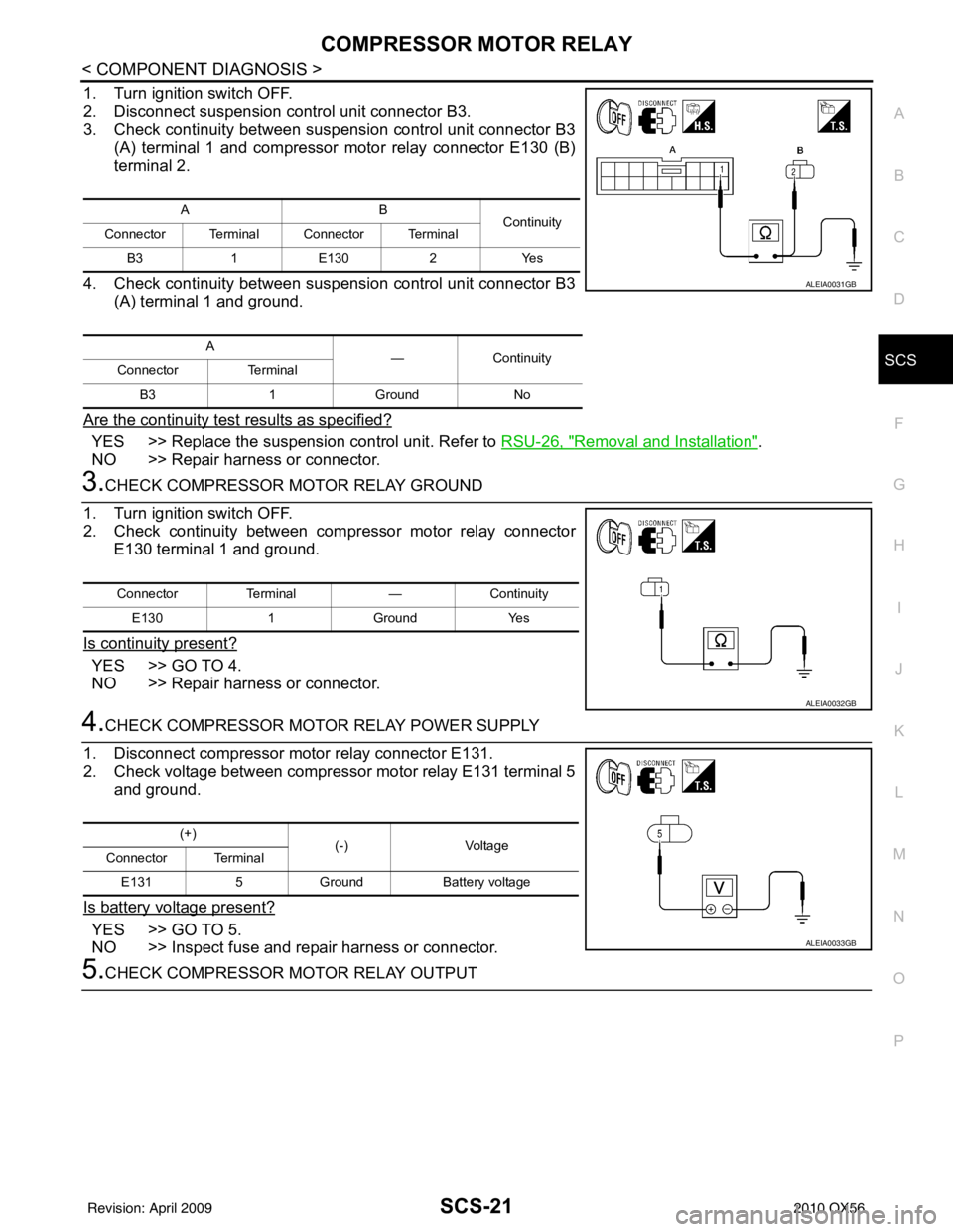
2. Disconnect suspension control unit connector B3.
3. Check continuity between suspension control unit connector B3 (A) terminal 1 and compressor motor relay connector E130 (B)
terminal 2.
4. Check continuity between suspension control unit connector B3 (A) terminal 1 and ground.
Are the continuity test results as specified?
YES >> Replace the suspension control unit. Refer to RSU-26, "Removal and Installation".
NO >> Repair harness or connector.
3.CHECK COMPRESSOR MOTOR RELAY GROUND
1. Turn ignition switch OFF.
2. Check continuity between compressor motor relay connector E130 terminal 1 and ground.
Is continuity present?
YES >> GO TO 4.
NO >> Repair harness or connector.
4.CHECK COMPRESSOR MOTOR RELAY POWER SUPPLY
1. Disconnect compressor motor relay connector E131.
2. Check voltage between compressor motor relay E131 terminal 5 and ground.
Is battery voltage present?
YES >> GO TO 5.
NO >> Inspect fuse and repair harness or connector.
5.CHECK COMPRESSOR MOTOR RELAY OUTPUT
AB Continuity
Connector Terminal Connector Terminal
B3 1E130 2Yes
A —Continuity
Connector Terminal
B3 1Ground No
ALEIA0031GB
ConnectorTerminal —Continuity
E130 1Ground Yes
ALEIA0032GB
(+)
(-)Voltage
Connector Terminal
E131 5Ground Battery voltage
ALEIA0033GB
Revision: April 20092010 QX56
Page 3254 of 4210
SCS-22
< COMPONENT DIAGNOSIS >
COMPRESSOR MOTOR RELAY
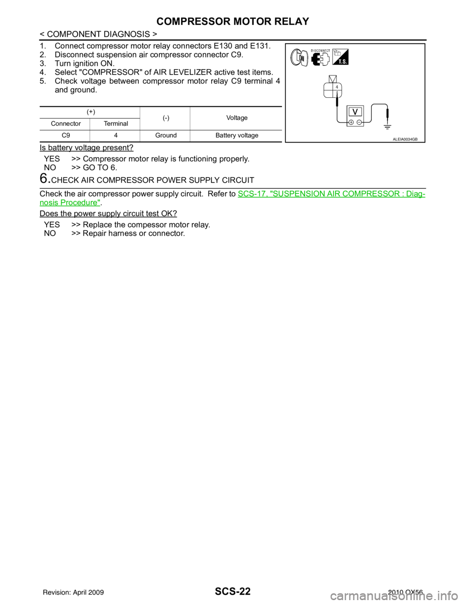
1. Connect compressor motor relay connectors E130 and E131.
2. Disconnect suspension air compressor connector C9.
3. Turn ignition ON.
4. Select "COMPRESSOR" of AIR LEVELIZER active test items.
5. Check voltage between compressor motor relay C9 terminal 4and ground.
Is battery voltage present?
YES >> Compressor motor relay is functioning properly.
NO >> GO TO 6.
6.CHECK AIR COMPRESSOR POWER SUPPLY CIRCUIT
Check the air compressor power supply circuit. Refer to SCS-17, "
SUSPENSION AIR COMPRESSOR : Diag-
nosis Procedure".
Does the power supply circuit test OK?
YES >> Replace the compessor motor relay.
NO >> Repair harness or connector.
(+) (-)Voltage
Connector Terminal
C9 4Ground Battery voltage
ALEIA0034GB
Revision: April 20092010 QX56