Page 3789 of 4210

TM-94
< COMPONENT DIAGNOSIS >
MAIN POWER SUPPLY AND GROUND CIRCUIT
MAIN POWER SUPPLY AND GROUND CIRCUIT
Diagnosis ProcedureINFOID:0000000005148678
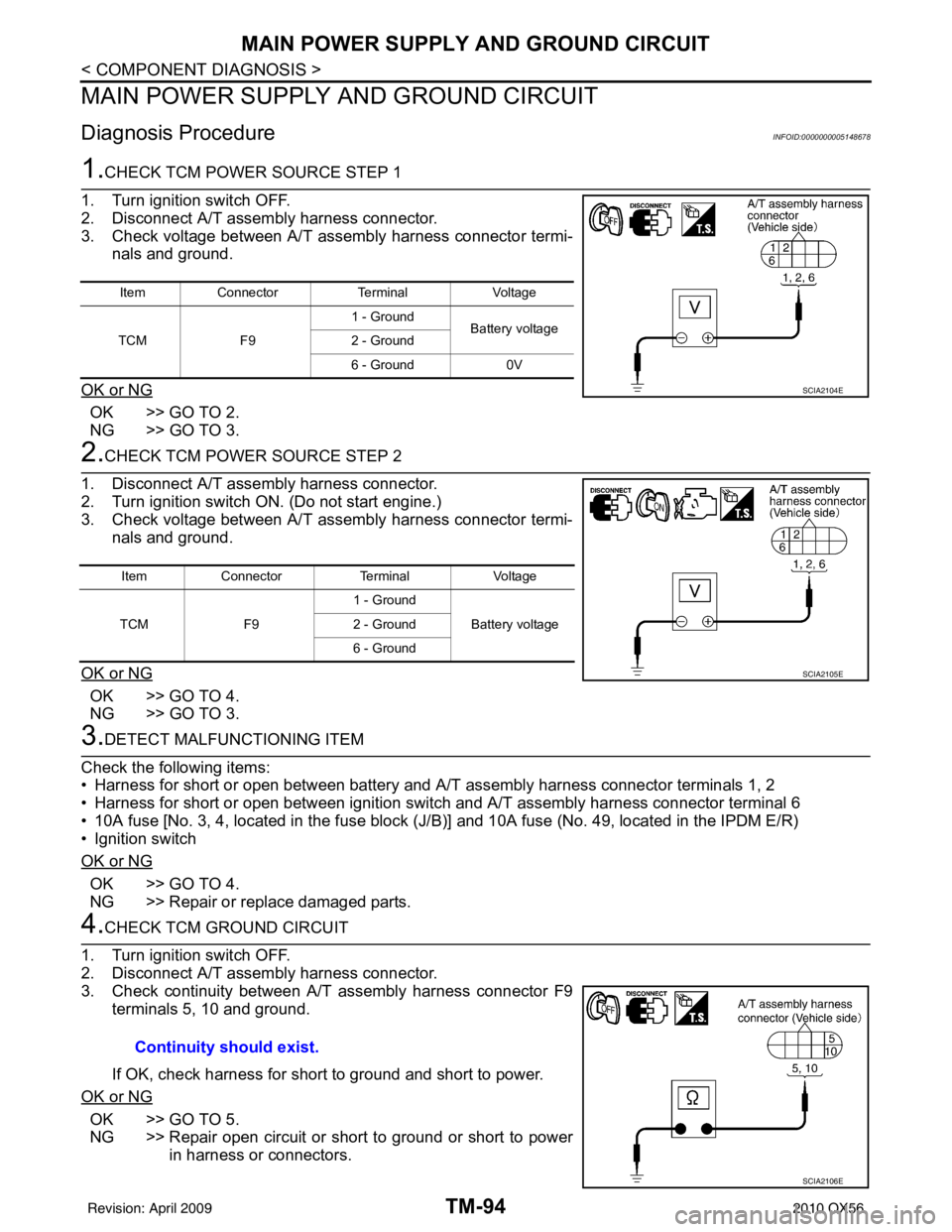
1.CHECK TCM POWER SOURCE STEP 1
1. Turn ignition switch OFF.
2. Disconnect A/T assembly harness connector.
3. Check voltage between A/T assembly harness connector termi- nals and ground.
OK or NG
OK >> GO TO 2.
NG >> GO TO 3.
2.CHECK TCM POWER SOURCE STEP 2
1. Disconnect A/T assembly harness connector.
2. Turn ignition switch ON. (Do not start engine.)
3. Check voltage between A/T assembly harness connector termi- nals and ground.
OK or NG
OK >> GO TO 4.
NG >> GO TO 3.
3.DETECT MALFUNCTIONING ITEM
Check the following items:
• Harness for short or open between battery and A/T assembly harness connector terminals 1, 2
• Harness for short or open between ignition switch and A/T assembly harness connector terminal 6
• 10A fuse [No. 3, 4, located in the fuse block (J /B)] and 10A fuse (No. 49, located in the IPDM E/R)
• Ignition switch
OK or NG
OK >> GO TO 4.
NG >> Repair or replace damaged parts.
4.CHECK TCM GROUND CIRCUIT
1. Turn ignition switch OFF.
2. Disconnect A/T assembly harness connector.
3. Check continuity between A/T assembly harness connector F9 terminals 5, 10 and ground.
If OK, check harness for short to ground and short to power.
OK or NG
OK >> GO TO 5.
NG >> Repair open circuit or short to ground or short to power in harness or connectors.
Item Connector TerminalVoltage
TCM F91 - Ground
Battery voltage
2 - Ground
6 - Ground 0V
SCIA2104E
ItemConnector TerminalVoltage
TCM F91 - Ground
Battery voltage
2 - Ground
6 - Ground
SCIA2105E
Continuity should exist.
SCIA2106E
Revision: April 20092010 QX56
Page 3794 of 4210

A/T SHIFT LOCK SYSTEMTM-99
< COMPONENT DIAGNOSIS >
CEF
G H
I
J
K L
M A
B
TM
N
O P
A/T SHIFT LOCK SYSTEM
DescriptionINFOID:0000000005203382
Refer to TM-29, "System Description".
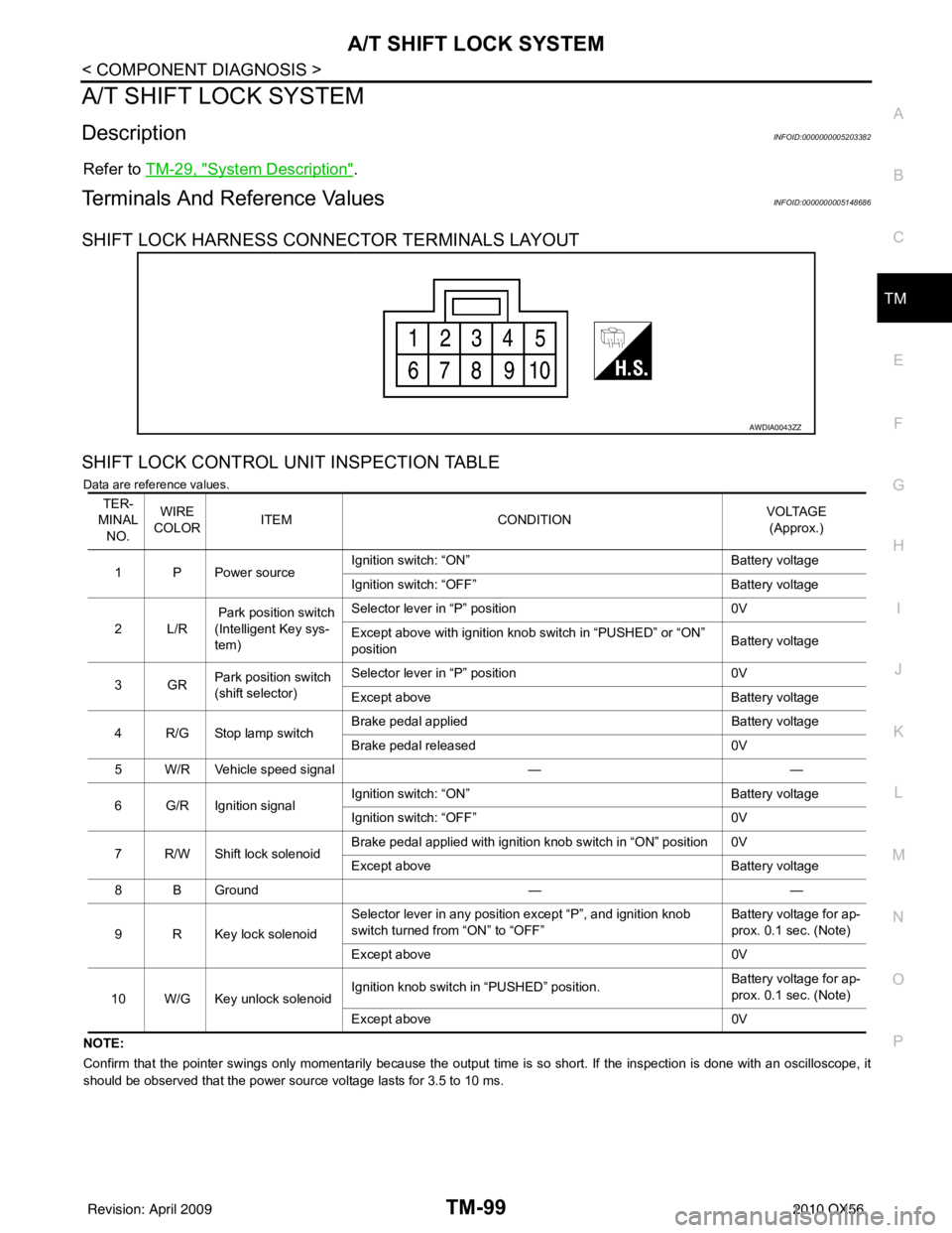
Terminals And Reference ValuesINFOID:0000000005148686
SHIFT LOCK HARNESS CONNECTOR TERMINALS LAYOUT
SHIFT LOCK CONTROL UNIT INSPECTION TABLE
Data are reference values.
NOTE:
Confirm that the pointer swings only momentarily because the output time is so short. If the inspection is done with an oscillo scope, it
should be observed that the power source voltage lasts for 3.5 to 10 ms.
AWDIA0043ZZ
TER-
MINAL NO. WIRE
COLOR ITEM
CONDITION VOLTAGE
(Approx.)
1 P Power source Ignition switch: “ON”
Battery voltage
Ignition switch: “OFF” Battery voltage
2L/R Park position switch
(Intelligent Key sys-
tem) Selector lever in “P” position
0V
Except above with ignition knob switch in “PUSHED” or “ON”
position Battery voltage
3GR Park position switch
(shift selector) Selector lever in “P” position
0V
Except above Battery voltage
4 R/G Stop lamp switch Brake pedal applied
Battery voltage
Brake pedal released 0V
5 W/R Vehicle speed signal ——
6 G/R Ignition signal Ignition switch: “ON”
Battery voltage
Ignition switch: “OFF” 0V
7 R/W Shift lock solenoid Brake pedal applied with ignition knob switch in “ON” position 0V
Except above
Battery voltage
8 B Ground ——
9 R Key lock solenoid Selector lever in any position except “P”, and ignition knob
switch turned from “ON” to “OFF”
Battery voltage for ap-
prox. 0.1 sec. (Note)
Except above 0V
10 W/G Key unlock solenoid Ignition knob switch in “PUSHED” position.
Battery voltage for ap-
prox. 0.1 sec. (Note)
Except above 0V
Revision: April 20092010 QX56
Page 3795 of 4210
TM-100
< COMPONENT DIAGNOSIS >
A/T SHIFT LOCK SYSTEM
Wiring Diagram - A/T SHIFT LOCK SYSTEM -
INFOID:0000000005148685
ABDWA0116GB
Revision: April 20092010 QX56
Page 3796 of 4210
A/T SHIFT LOCK SYSTEMTM-101
< COMPONENT DIAGNOSIS >
CEF
G H
I
J
K L
M A
B
TM
N
O P
AADIA0120GB
Revision: April 20092010 QX56
Page 3797 of 4210
TM-102
< COMPONENT DIAGNOSIS >
A/T SHIFT LOCK SYSTEM
AADIA0121GB
Revision: April 20092010 QX56
Page 3798 of 4210
A/T SHIFT LOCK SYSTEMTM-103
< COMPONENT DIAGNOSIS >
CEF
G H
I
J
K L
M A
B
TM
N
O P
Component InspectionINFOID:0000000005148687
SHIFT LOCK SOLENOID
ABDIA0045GB
Revision: April 20092010 QX56
Page 3799 of 4210

TM-104
< COMPONENT DIAGNOSIS >
A/T SHIFT LOCK SYSTEM
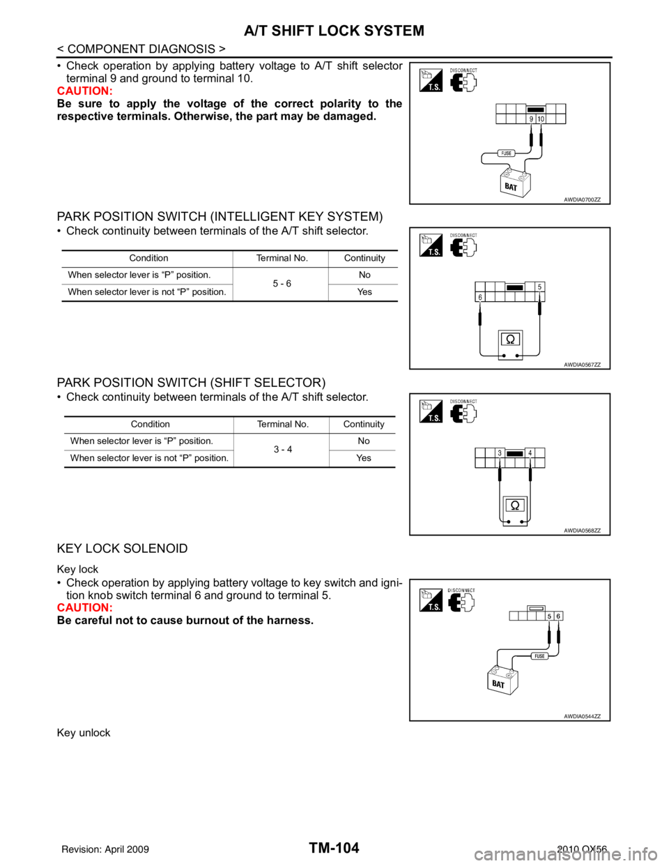
• Check operation by applying battery voltage to A/T shift selectorterminal 9 and ground to terminal 10.
CAUTION:
Be sure to apply the voltage of the correct polarity to the
respective terminals. Otherwise, the part may be damaged.
PARK POSITION SWITCH (INTELLIGENT KEY SYSTEM)
• Check continuity between terminals of the A/T shift selector.
PARK POSITION SWITCH (SHIFT SELECTOR)
• Check continuity between terminals of the A/T shift selector.
KEY LOCK SOLENOID
Key lock
• Check operation by applying battery voltage to key switch and igni- tion knob switch terminal 6 and ground to terminal 5.
CAUTION:
Be careful not to cause burnout of the harness.
Key unlock
AWDIA0700ZZ
Condition Terminal No. Continuity
When selector lever is “P” position. 5 - 6No
When selector lever is not “P” position. Yes
AWDIA0567ZZ
ConditionTerminal No. Continuity
When selector lever is “P” position. 3 - 4No
When selector lever is not “P” position. Yes
AWDIA0568ZZ
AWDIA0544ZZ
Revision: April 20092010 QX56
Page 3800 of 4210
A/T SHIFT LOCK SYSTEMTM-105
< COMPONENT DIAGNOSIS >
CEF
G H
I
J
K L
M A
B
TM
N
O P
• Check operation by applying battery voltage to key switch and igni- tion knob switch terminal 5 and ground to terminal 6.
CAUTION:
Be careful not to cause burnout of the harness.
IGNITION KNOB SWITCH
• Check continuity between terminals of the key switch and ignition
knob switch.
STOP LAMP SWITCH
• Check continuity between terminals of the stop lamp switch har-ness connector.
Check stop lamp switch after adjusting brake pedal.
AWDIA0545ZZ
Condition Terminal No. Continuity
Switch pushed 1 - 2Ye s
Switch released No
AWDIA0546ZZ
ConditionTerminal No. Continuity
When brake pedal is applied 3 -4Ye s
When brake pedal is released No
AWDIA0419ZZ
Revision: April 20092010 QX56