Page 3078 of 4210
BCM (BODY CONTROL MODULE)PWC-93
< ECU DIAGNOSIS >
C
DE
F
G H
I
J
L
M A
B
PWC
N
O P
ABMIA1059GB
Revision: April 20092010 QX56
Page 3079 of 4210
PWC-94
< ECU DIAGNOSIS >
BCM (BODY CONTROL MODULE)
Fail Safe
INFOID:0000000005367563
Fail-safe index
BCM performs fail-safe control when any DTC listed below is detected.
ABMIA1060GB
Revision: April 20092010 QX56
Page 3080 of 4210
BCM (BODY CONTROL MODULE)PWC-95
< ECU DIAGNOSIS >
C
DE
F
G H
I
J
L
M A
B
PWC
N
O P
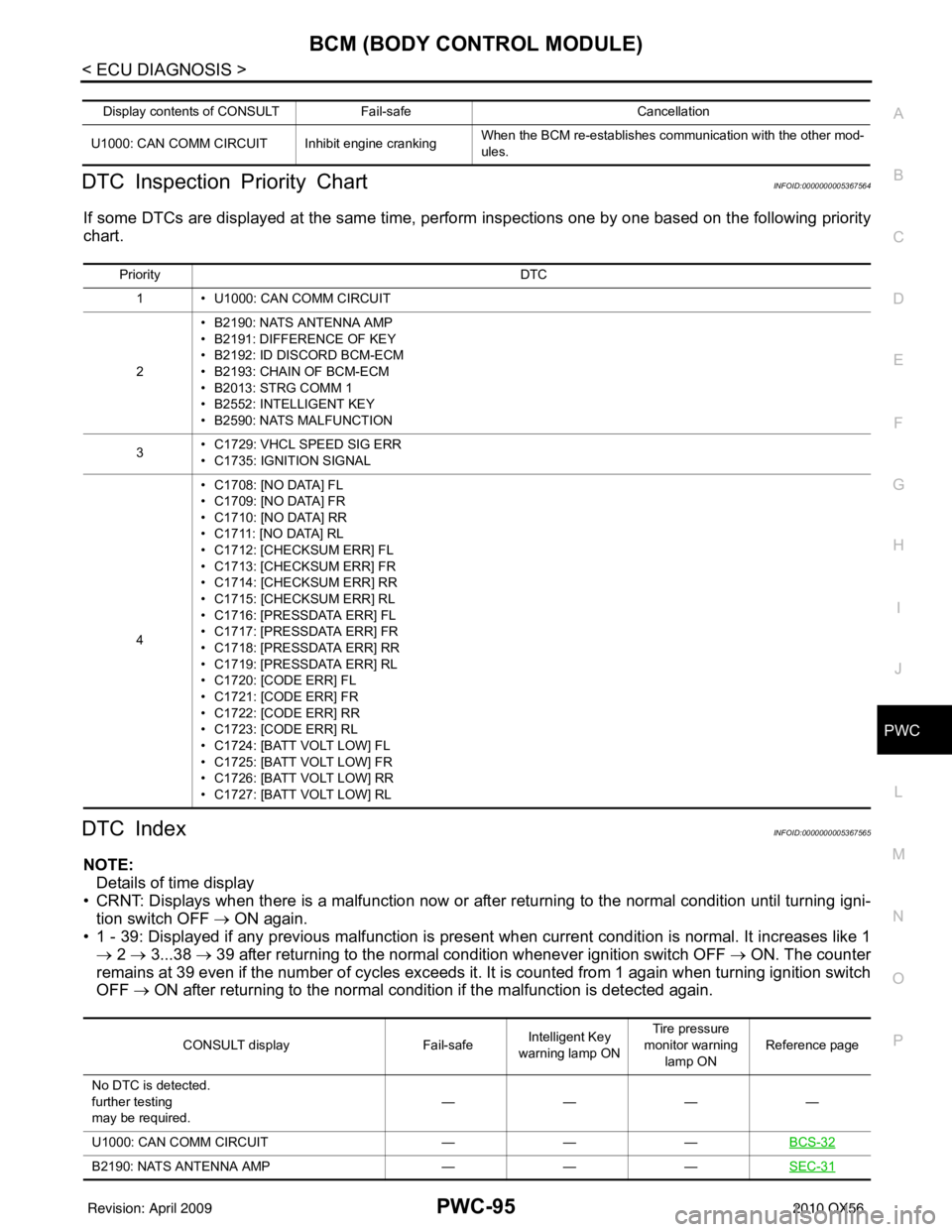
DTC Inspection Priority ChartINFOID:0000000005367564
If some DTCs are displayed at the same time, perform inspections one by one based on the following priority
chart.
DTC IndexINFOID:0000000005367565
NOTE: Details of time display
• CRNT: Displays when there is a malfunction now or after returning to the normal condition until turning igni- tion switch OFF → ON again.
• 1 - 39: Displayed if any previous ma lfunction is present when current conditi on is normal. It increases like 1
→ 2 → 3...38 → 39 after returning to the normal condition whenever ignition switch OFF → ON. The counter
remains at 39 even if the number of cycles exceeds it. It is counted from 1 again when turning ignition switch
OFF → ON after returning to the normal condi tion if the malfunction is detected again.
Display contents of CONSULT Fail-safe Cancellation
U1000: CAN COMM CIRCUIT I nhibit engine crankingWhen the BCM re-establishes communication with the other mod-
ules.
Priority
DTC
1 • U1000: CAN COMM CIRCUIT
2 • B2190: NATS ANTENNA AMP
• B2191: DIFFERENCE OF KEY
• B2192: ID DISCORD BCM-ECM
• B2193: CHAIN OF BCM-ECM
• B2013: STRG COMM 1
• B2552: INTELLIGENT KEY
• B2590: NATS MALFUNCTION
3 • C1729: VHCL SPEED SIG ERR
• C1735: IGNITION SIGNAL
4 • C1708: [NO DATA] FL
• C1709: [NO DATA] FR
• C1710: [NO DATA] RR
• C1711: [NO DATA] RL
• C1712: [CHECKSUM ERR] FL
• C1713: [CHECKSUM ERR] FR
• C1714: [CHECKSUM ERR] RR
• C1715: [CHECKSUM ERR] RL
• C1716: [PRESSDATA ERR] FL
• C1717: [PRESSDATA ERR] FR
• C1718: [PRESSDATA ERR] RR
• C1719: [PRESSDATA ERR] RL
• C1720: [CODE ERR] FL
• C1721: [CODE ERR] FR
• C1722: [CODE ERR] RR
• C1723: [CODE ERR] RL
• C1724: [BATT VOLT LOW] FL
• C1725: [BATT VOLT LOW] FR
• C1726: [BATT VOLT LOW] RR
• C1727: [BATT VOLT LOW] RL
CONSULT display
Fail-safeIntelligent Key
warning lamp ON Tire pressure
monitor warning lamp ON Reference page
No DTC is detected.
further testing
may be required. ————
U1000: CAN COMM CIRCUIT ———BCS-32
B2190: NATS ANTENNA AMP ———SEC-31
Revision: April 20092010 QX56
Page 3081 of 4210
PWC-96
< ECU DIAGNOSIS >
BCM (BODY CONTROL MODULE)
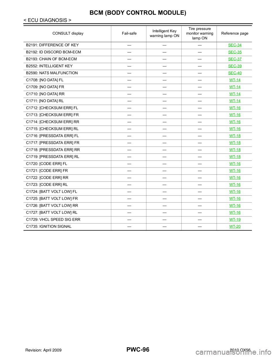
B2191: DIFFERENCE OF KEY———SEC-34
B2192: ID DISCORD BCM-ECM ———SEC-35
B2193: CHAIN OF BCM-ECM ———SEC-37
B2552: INTELLIGENT KEY ———SEC-39
B2590: NATS MALFUNCTION ———SEC-40
C1708: [NO DATA] FL ———WT-14
C1709: [NO DATA] FR ———WT-14
C1710: [NO DATA] RR ———WT-14
C1711: [NO DATA] RL ———WT-14
C1712: [CHECKSUM ERR] FL ———WT-16
C1713: [CHECKSUM ERR] FR ———WT-16
C1714: [CHECKSUM ERR] RR ———WT-16
C1715: [CHECKSUM ERR] RL ———WT-16
C1716: [PRESSDATA ERR] FL ———WT-18
C1717: [PRESSDATA ERR] FR ———WT-18
C1718: [PRESSDATA ERR] RR ———WT-18
C1719: [PRESSDATA ERR] RL ———WT-18
C1720: [CODE ERR] FL ———WT-16
C1721: [CODE ERR] FR ———WT-16
C1722: [CODE ERR] RR ———WT-16
C1723: [CODE ERR] RL ———WT-16
C1724: [BATT VOLT LOW] FL ———WT-16
C1725: [BATT VOLT LOW] FR ———WT-16
C1726: [BATT VOLT LOW] RR ———WT-16
C1727: [BATT VOLT LOW] RL ———WT-16
C1729: VHCL SPEED SIG ERR ———WT-19
C1735: IGNITION SIGNAL ———WT-20
CONSULT display Fail-safeIntelligent Key
warning lamp ON Tire pressure
monitor warning
lamp ON Reference page
Revision: April 20092010 QX56
Page 3123 of 4210
REAR DRIVE SHAFTRAX-11
< DISASSEMBLY AND ASSEMBLY >
CEF
G H
I
J
K L
M A
B
RAX
N
O P
DISASSEMBLY AND ASSEMBLY
REAR DRIVE SHAFT
Disassembly and AssemblyINFOID:0000000005274245
DISASSEMBLY
Final Drive Side
1. Secure the drive shaft in a vise. CAUTION:
When securing the drive shaft in a vise, use copper or aluminum plates between the vise and the
drive shaft.
2. Remove the boot bands.
3. If the plug needs to be removed, move the boot to t he wheel side, then drive the plug out using a suitable
tool.
4. Remove the stopper ring using a suitable tool as shown, and pull the housing out.
1. Plug 2. Housing3. Snap ring
4. Ball cage, steel ball, inner race assembly 5. Stopper ring 6. Boot band
7. Boot 8. Shaft9. Circlip
10. Joint sub-assembly
SDIA1488E
SRA249A
Revision: April 20092010 QX56
Page 3124 of 4210
RAX-12
< DISASSEMBLY AND ASSEMBLY >
REAR DRIVE SHAFT
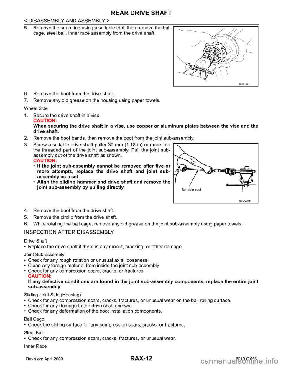
5. Remove the snap ring using a suitable tool, then remove the ballcage, steel ball, inner race assembly from the drive shaft.
6. Remove the boot from the drive shaft.
7. Remove any old grease on the housing using paper towels.
Wheel Side
1. Secure the drive shaft in a vise. CAUTION:
When securing the drive shaft in a vise, use copp er or aluminum plates between the vise and the
drive shaft.
2. Remove the boot bands, then remove the boot from the joint sub-assembly.
3. Screw a suitable drive shaft puller 30 mm (1.18 in) or more into the threaded part of the joint sub-assembly. Pull the joint sub-
assembly out of the drive shaft as shown.
CAUTION:
• If the joint sub-assembly cannot be removed after five ormore attempts, replace the drive shaft and joint sub-
assembly as a set.
• Align the sliding hammer and drive shaft and remove the
joint sub-assembly by pulling directly.
4. Remove the boot from the drive shaft.
5. Remove the circlip from the drive shaft.
6. While rotating the ball cage, remove any old grease on the joint sub-assembly using paper towels.
INSPECTION AFTER DISASSEMBLY
Drive Shaft
• Replace the drive shaft if there is any runout, cracking, or other damage.
Joint Sub-assembly
• Check for any rough rotation or unusual axial looseness.
• Clean any foreign material from inside the joint sub-assembly.
• Check for any compression scars, cracks, or fractures.
CAUTION:
If any defective conditions are found in the joint sub-assembly comp onents, replace the entire joint
sub-assembly.
Sliding Joint Side (Housing)
• Check for any compression scars, cracks, fracture s, or unusual wear on the ball rolling surface.
• Check for any damage to the drive shaft screws.
• Check for any deformation of the boot installation components.
Ball Cage
• Check the sliding surface for any compression scars, cracks, or fractures.
Steel Ball
• Check for any compression scars, cr acks, fractures, or unusual wear.
Inner Race
SFA514A
SDIA0606E
Revision: April 20092010 QX56
Page 3125 of 4210
REAR DRIVE SHAFTRAX-13
< DISASSEMBLY AND ASSEMBLY >
CEF
G H
I
J
K L
M A
B
RAX
N
O P
• Check the ball sliding surface for any co mpression scars, cracks, or fractures.
• Check for any damage to the serrated part. CAUTION:
If any defective conditions are found, install a new housing, ball cage, steel ball, and inner race as a
set.
ASSEMBLY
Final Drive Side
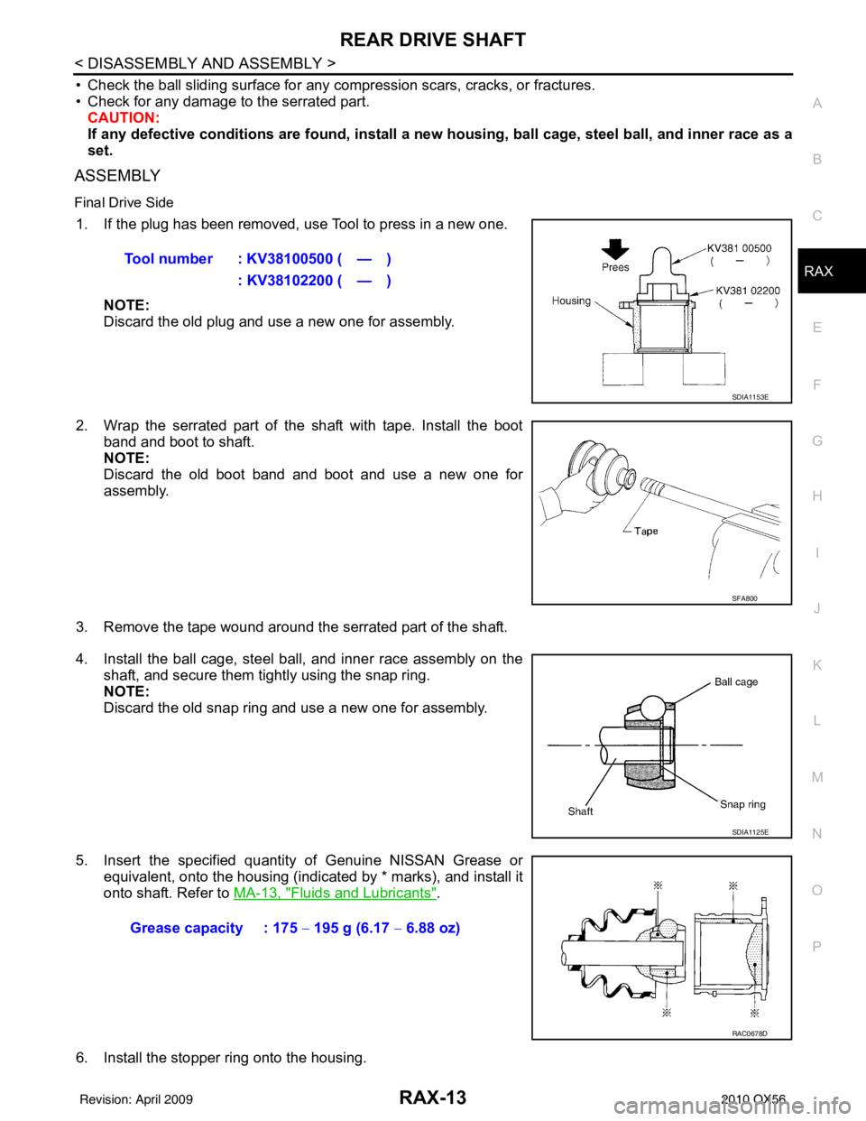
1. If the plug has been removed, use Tool to press in a new one.
NOTE:
Discard the old plug and use a new one for assembly.
2. Wrap the serrated part of the shaft with tape. Install the boot band and boot to shaft.
NOTE:
Discard the old boot band and boot and use a new one for
assembly.
3. Remove the tape wound around the serrated part of the shaft.
4. Install the ball cage, steel ball, and inner race assembly on the shaft, and secure them tightly using the snap ring.
NOTE:
Discard the old snap ring and use a new one for assembly.
5. Insert the specified quantity of Genuine NISSAN Grease or equivalent, onto the housing (indicated by * marks), and install it
onto shaft. Refer to MA-13, "
Fluids and Lubricants".
6. Install the stopper ring onto the housing. Tool number : KV38100500 ( — )
: KV38102200 ( — )
SDIA1153E
SFA800
SDIA1125E
Grease capacity : 175 − 195 g (6.17 − 6.88 oz)
RAC0678D
Revision: April 20092010 QX56
Page 3126 of 4210
RAX-14
< DISASSEMBLY AND ASSEMBLY >
REAR DRIVE SHAFT
7. After installation, pull on the shaft to check engagement between the joint sub-assembly and the stopper
ring.
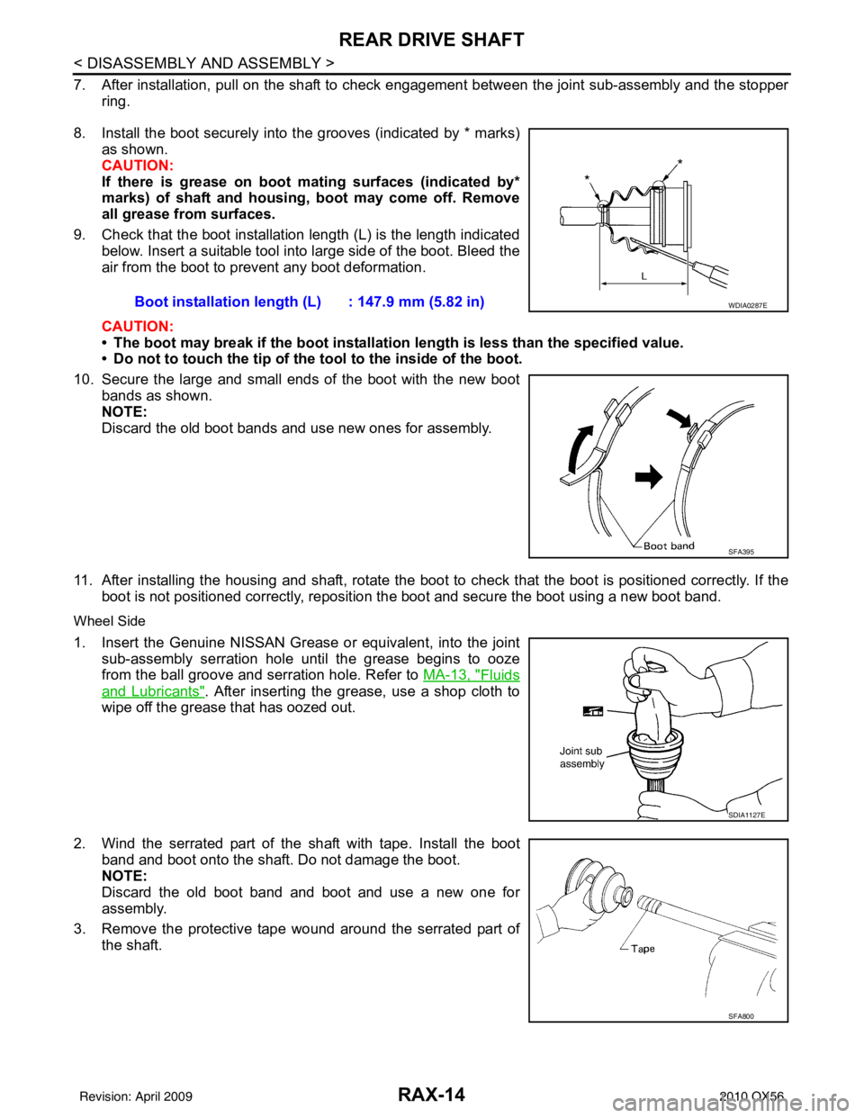
8. Install the boot securely into the grooves (indicated by * marks) as shown.
CAUTION:
If there is grease on boot mating surfaces (indicated by*
marks) of shaft and housing, boot may come off. Remove
all grease from surfaces.
9. Check that the boot installation length (L) is the length indicated below. Insert a suitable tool into large side of the boot. Bleed the
air from the boot to prevent any boot deformation.
CAUTION:
• The boot may break if the boot installation length is less than the specified value.
• Do not to touch the tip of the t ool to the inside of the boot.
10. Secure the large and small ends of the boot with the new boot bands as shown.
NOTE:
Discard the old boot bands and use new ones for assembly.
11. After installing the housing and shaft, rotate the boot to check that the boot is positioned correctly. If the boot is not positioned correctly, reposition t he boot and secure the boot using a new boot band.
Wheel Side
1. Insert the Genuine NISSAN Grease or equivalent, into the joint
sub-assembly serration hole until the grease begins to ooze
from the ball groove and serration hole. Refer to MA-13, "
Fluids
and Lubricants". After inserting the grease, use a shop cloth to
wipe off the grease that has oozed out.
2. Wind the serrated part of the shaft with tape. Install the boot
band and boot onto the shaft. Do not damage the boot.
NOTE:
Discard the old boot band and boot and use a new one for
assembly.
3. Remove the protective tape wound around the serrated part of the shaft. Boot installation length
(L) : 147.9 mm (5.82 in)
WDIA0287E
SFA395
SDIA1127E
SFA800
Revision: April 20092010 QX56