2010 INFINITI QX56 ECU
[x] Cancel search: ECUPage 3166 of 4210
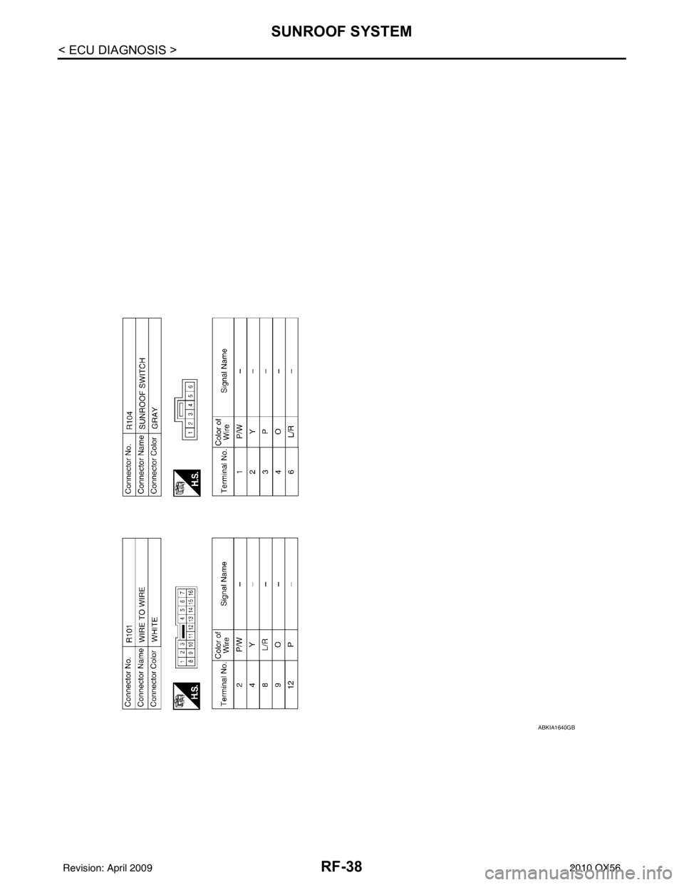
RF-38
< ECU DIAGNOSIS >
SUNROOF SYSTEM
ABKIA1640GB
Revision: April 20092010 QX56
Page 3173 of 4210
SQUEAK AND RATTLE TROUBLE DIAGNOSESRF-45
< SYMPTOM DIAGNOSIS >
C
DE
F
G H
I
J
L
M A
B
RF
N
O P
If the noise can be duplicated easily during the test drive, to help identify the source of the noise, try to dupli-
cate the noise with the vehicle stopped by doing one or all of the following:
1) Close a door.
2) Tap or push/pull around the area where the noise appears to be coming from.
3) Rev the engine.
4) Use a floor jack to recreate vehicle “twist”.
5) At idle, apply engine load. With brakes appllied, place A/T shift selector in drive position.
6) Raise the vehicle on a hoist and hit a tire with a rubber hammer.
• Drive the vehicle and attempt to duplicate the conditions the customer states exist when the noise occurs.
• If it is difficult to duplicate the noise, drive the vehicle slowly on an undulating or rough road to stress the
vehicle body.
CHECK RELATED SERVICE BULLETINS
After verifying the customer concern or symptom, check ASIST for Technical Service Bulletins (TSBs) related
to that concern or symptom.
If a TSB relates to the symptom, follow the procedure to repair the noise.
LOCATE THE NOISE AND IDENTIFY THE ROOT CAUSE
1. Narrow down the noise to a general area. To help pinpoint the source of the noise, use a listening tool (Chassis Ear: J-39570, Engine Ear and mechanics stethoscope).
2. Narrow down the noise to a more specific area and identify the cause of the noise by:
• removing the components in the area that you suspect the noise is coming from. Do not use too much force when removing clips and fasteners, otherwise clips and fastener can be broken
or lost during the repair, resulting in the creation of new noise.
• tapping or pushing/pulling the component that you suspect is causing the noise.
Do not tap or push/pull the component with excessive force, otherwise the noise will be eliminated only tem-
porarily.
• feeling for a vibration with your hand by touching the component(s) that you suspect is (are) causing the
noise.
• placing a piece of paper between components that you suspect are causing the noise.
• looking for loose components and contact marks. Refer to RF-46, "
Generic Squeak and Rattle Troubleshooting".
REPAIR THE CAUSE
• If the cause is a loose component, tighten the component securely.
• If the cause is insufficient clearance between components:
- separate components by repositioning or loos ening and retightening the component, if possible.
- insulate components with a suitable insulator such as urethane pads, foam blocks, felt cloth tape or urethane tape. A Nissan Squeak and Rattle Kit (J-43980) is av ailable through your authorized Nissan Parts Depart-
ment.
CAUTION:
Do not use excessive force as many components are constructed of plastic and may be damaged.
NOTE:
Always check with the Parts Department for the latest parts information.
The following materials are contained in the Niss an Squeak and Rattle Kit (J-43980). Each item can be
ordered separately as needed.
URETHANE PADS [1.5 mm (0.059 in) thick]
Insulates connectors, harness, etc.
76268-9E005: 100 ×135 mm (3.94 ×5.31 in)/76884-71L01: 60 ×85 mm (2.36 ×3.35 in)/76884-
71L02: 15 ×25 mm (0.59 ×0.98 in)
INSULATOR (Foam blocks)
Insulates components from contact. Can be used to fill space behind a panel.
73982-9E000: 45 mm (1.77 in) thick, 50 ×50 mm (1.97 ×1.97 in)/73982-
50Y00: 10 mm (0.39 in) thick, 50 ×50 mm (1.97 ×1.97 in)
INSULATOR (Light foam block)
80845-71L00: 30 mm (1.18 in) thick, 30 ×50 mm (1.18 ×1.97 in)
FELT CLOTHTAPE
Used to insulate where movement does not occur. Ideal for instrument panel applications.
68370-4B000: 15 ×25 mm (0.59 ×0.98 in) pad/68239-13E00: 5 mm (0.20 in) wide tape roll
The following materials, not found in the kit, can also be used to repair squeaks and rattles.
UHMW (TEFLON) TAPE
Revision: April 20092010 QX56
Page 3175 of 4210

SQUEAK AND RATTLE TROUBLE DIAGNOSESRF-47
< SYMPTOM DIAGNOSIS >
C
DE
F
G H
I
J
L
M A
B
RF
N
O P
Most of these incidents can be repaired by adjusting, se curing or insulating the item(s) or component(s) caus-
ing the noise.
SUNROOF/HEADLINING
Noises in the sunroof/headlining area can often be traced to one of the following:
1. Sunroof lid, rail, linkage or seals making a rattle or light knocking noise
2. Sun visor shaft shaking in the holder
3. Front or rear windshield touching headliner and squeaking
Again, pressing on the components to stop the noise while duplicating the conditions can isolate most of these
incidents. Repairs usually consist of insulating with felt cloth tape.
OVERHEAD CONSOLE (FRONT AND REAR)
Overhead console noises are often caused by the cons ole panel clips not being engaged correctly. Most of
these incidents are repaired by pushing up on the c onsole at the clip locations until the clips engage.
In addition look for:
1. Loose harness or harness connectors.
2. Front console map/reading lamp lens loose.
3. Loose screws at console attachment points.
SEATS
When isolating seat noise it's important to note the position the seat is in and the load placed on the seat when
the noise is present. These conditions should be duplicated when verifying and isolating the cause of the
noise.
Cause of seat noise include:
1. Headrest rods and holder
2. A squeak between the seat pad cushion and frame
3. The rear seatback lock and bracket
These noises can be isolated by moving or pressing on the suspected components while duplicating the con-
ditions under which the noise occurs. Most of thes e incidents can be repaired by repositioning the component
or applying urethane tape to the contact area.
UNDERHOOD
Some interior noise may be caused by components under the hood or on the engine wall. The noise is then
transmitted into the passenger compartment.
Causes of transmitted underhood noise include:
1. Any component installed to the engine wall
2. Components that pass through the engine wall
3. Engine wall mounts and connectors
4. Loose radiator installation pins
5. Hood bumpers out of adjustment
6. Hood striker out of adjustment
These noises can be difficult to isolate since they cannot be reached from the interior of the vehicle. The best
method is to secure, move or insulate one component at a time and test drive the vehicle. Also, engine RPM
or load can be changed to isolate the noise. Repairs can usually be made by moving, adjusting, securing, or
insulating the component causing the noise.
Revision: April 20092010 QX56
Page 3183 of 4210
SUNROOF SYSTEMRF-55
< ON-VEHICLE REPAIR >
C
DE
F
G H
I
J
L
M A
B
RF
N
O P
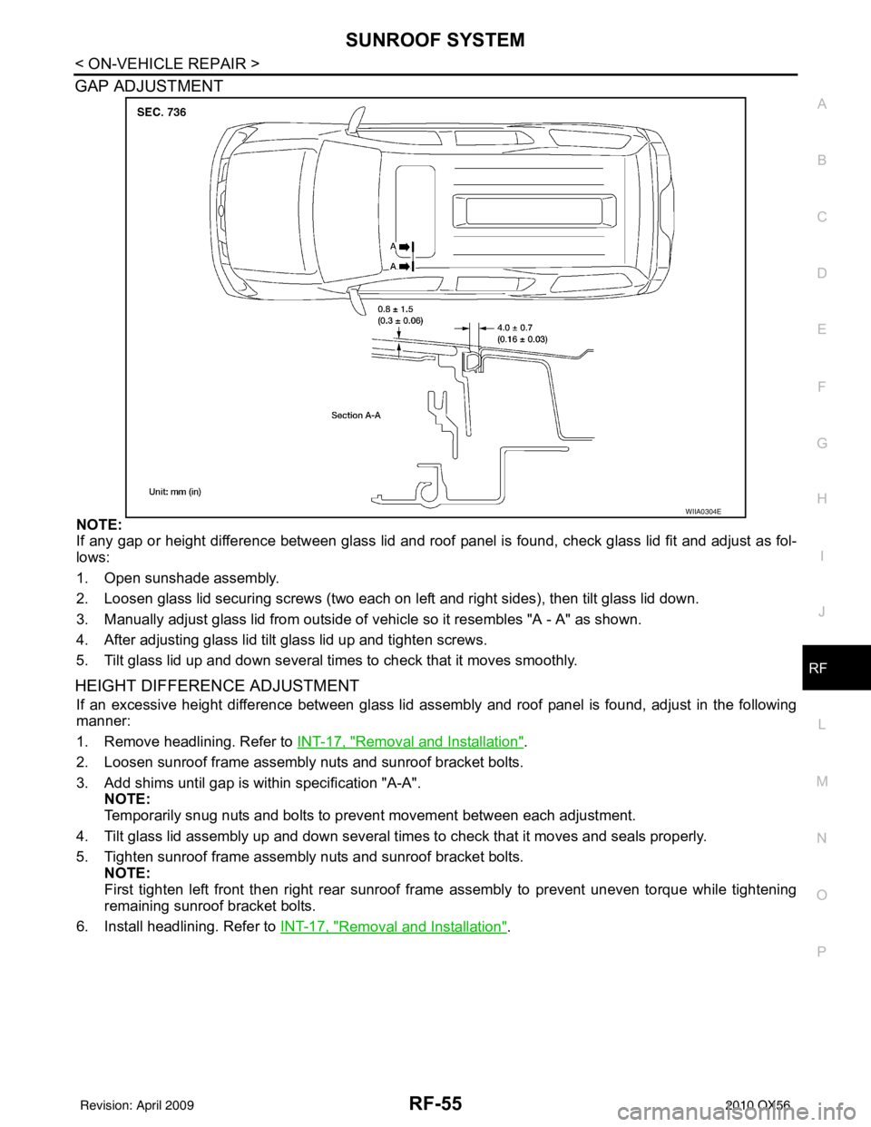
GAP ADJUSTMENT
NOTE:
If any gap or height difference between glass lid and roof panel is found, check glass lid fit and adjust as fol-
lows:
1. Open sunshade assembly.
2. Loosen glass lid securing screws (two each on left and right sides), then tilt glass lid down.
3. Manually adjust glass lid from outside of v ehicle so it resembles "A - A" as shown.
4. After adjusting glass lid tilt glass lid up and tighten screws.
5. Tilt glass lid up and down several times to check that it moves smoothly.
HEIGHT DIFFERE NCE ADJUSTMENT
If an excessive height difference between glass lid assemb ly and roof panel is found, adjust in the following
manner:
1. Remove headlining. Refer to INT-17, "
Removal and Installation".
2. Loosen sunroof frame assembly nuts and sunroof bracket bolts.
3. Add shims until gap is within specification "A-A". NOTE:
Temporarily snug nuts and bolts to prevent movement between each adjustment.
4. Tilt glass lid assembly up and down several times to check that it moves and seals properly.
5. Tighten sunroof frame assembly nuts and sunroof bracket bolts. NOTE:
First tighten left front then right rear sunroof frame assembly to prevent uneven torque while tightening
remaining sunroof bracket bolts.
6. Install headlining. Refer to INT-17, "
Removal and Installation".
WIIA0304E
Revision: April 20092010 QX56
Page 3186 of 4210
RF-58
< ON-VEHICLE REPAIR >
SUNROOF SYSTEM
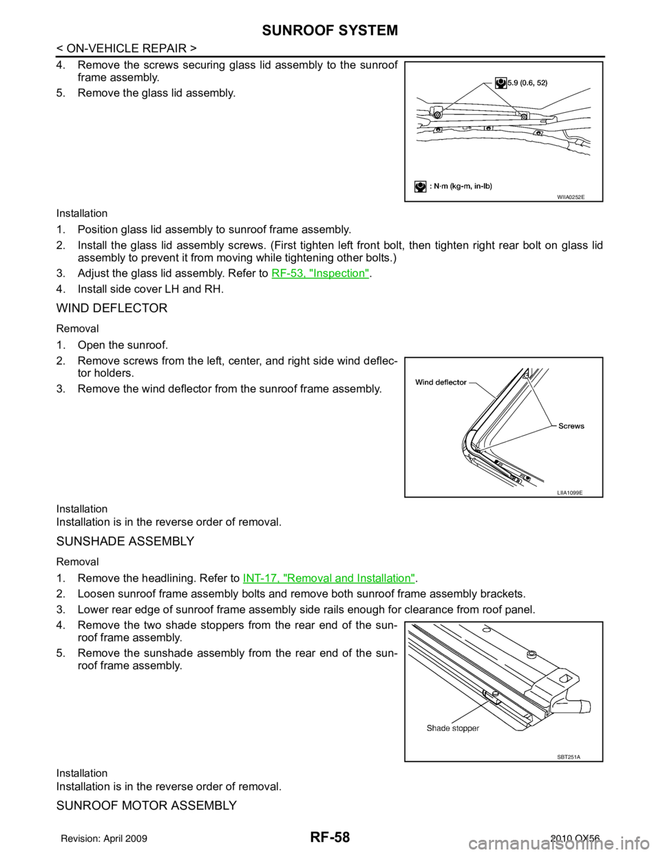
4. Remove the screws securing glass lid assembly to the sunroofframe assembly.
5. Remove the glass lid assembly.
Installation
1. Position glass lid assembly to sunroof frame assembly.
2. Install the glass lid assembly screws. (First tighten left front bolt, then tighten right rear bolt on glass lid
assembly to prevent it from moving while tightening other bolts.)
3. Adjust the glass lid assembly. Refer to RF-53, "
Inspection".
4. Install side cover LH and RH.
WIND DEFLECTOR
Removal
1. Open the sunroof.
2. Remove screws from the left, center, and right side wind deflec- tor holders.
3. Remove the wind deflector from the sunroof frame assembly.
Installation
Installation is in the reverse order of removal.
SUNSHADE ASSEMBLY
Removal
1. Remove the headlining. Refer to INT-17, "Removal and Installation".
2. Loosen sunroof frame assembly bolts and remove both sunroof frame assembly brackets.
3. Lower rear edge of sunroof frame assembly side rails enough for clearance from roof panel.
4. Remove the two shade stoppers from the rear end of the sun- roof frame assembly.
5. Remove the sunshade assembly from the rear end of the sun- roof frame assembly.
Installation
Installation is in the reverse order of removal.
SUNROOF MOTOR ASSEMBLY
WIIA0252E
LIIA1099E
SBT251A
Revision: April 20092010 QX56
Page 3187 of 4210
SUNROOF SYSTEMRF-59
< ON-VEHICLE REPAIR >
C
DE
F
G H
I
J
L
M A
B
RF
N
O P
Removal
CAUTION:
• When removing the sunroof motor, be sure to
place the link and wire assembly in the symmetrical
and fully closed position.
• Never run the removed sunroof motor assembly as a single unit.
1. Position the sunroof in the fully closed position.
2. Remove the roof console assembly. Refer to INT-17, "
Removal and Installation".
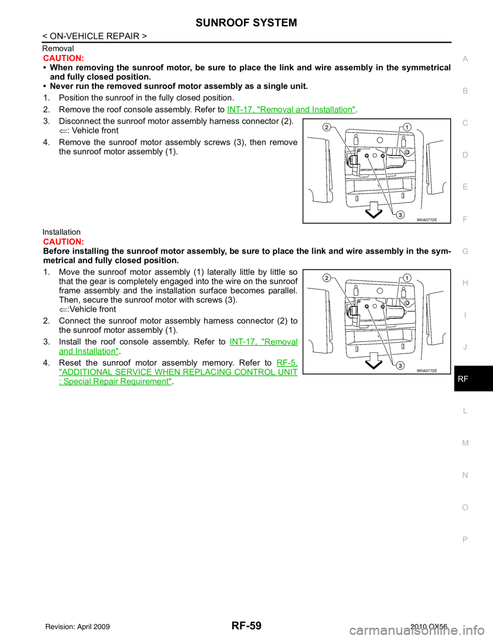
3. Disconnect the sunroof motor assembly harness connector (2). ⇐: Vehicle front
4. Remove the sunroof motor assembly screws (3), then remove the sunroof motor assembly (1).
Installation
CAUTION:
Before installing the sunroof motor assembly, be sure to place the link and wire assembly in the sym-
metrical and fully closed position.
1. Move the sunroof motor assembly (1) laterally little by little so
that the gear is completely engaged into the wire on the sunroof
frame assembly and the installation surface becomes parallel.
Then, secure the sunroof motor with screws (3).
⇐:Vehicle front
2. Connect the sunroof motor assembly harness connector (2) to the sunroof motor assembly (1).
3. Install the roof console assembly. Refer to INT-17, "
Removal
and Installation".
4. Reset the sunroof motor assembly memory. Refer to RF-5,
"ADDITIONAL SERVICE WHEN REPLACING CONTROL UNIT
: Special Repair Requirement".
WIIA0772E
WIIA0772E
Revision: April 20092010 QX56
Page 3201 of 4210
RSU-14
< REMOVAL AND INSTALLATION >
REAR SUSPENSION MEMBER
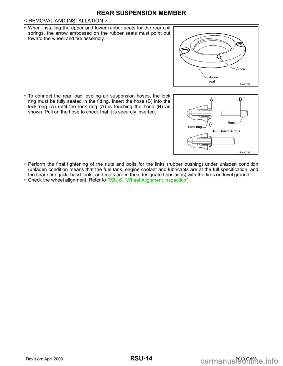
• When installing the upper and lower rubber seats for the rear coilsprings, the arrow embossed on the rubber seats must point out
toward the wheel and tire assembly.
• To connect the rear load leveling air suspension hoses, the lock ring must be fully seated in the fitt ing. Insert the hose (B) into the
lock ring (A) until the lock ring (A) is touching the hose (B) as
shown. Pull on the hose to check that it is securely inserted.
• Perform the final tightening of the nuts and bolts for the links (rubber bushing) under unladen condition (unladen condition means that the fuel tank, engine cool ant and lubricants are at the full specification, and
the spare tire, jack, hand tools, and mats are in t heir designated positions) with the tires on level ground.
• Check the wheel alignment. Refer to RSU-6, "
Wheel Alignment Inspection" .
LEIA0076E
LEIA0078E
Revision: April 20092010 QX56
Page 3212 of 4210
REAR LOAD LEVELING AIR SUSPENSION COMPRESSOR ASSEMBLYRSU-25
< REMOVAL AND INSTALLATION >
C
DF
G H
I
J
K L
M A
B
RSU
N
O P
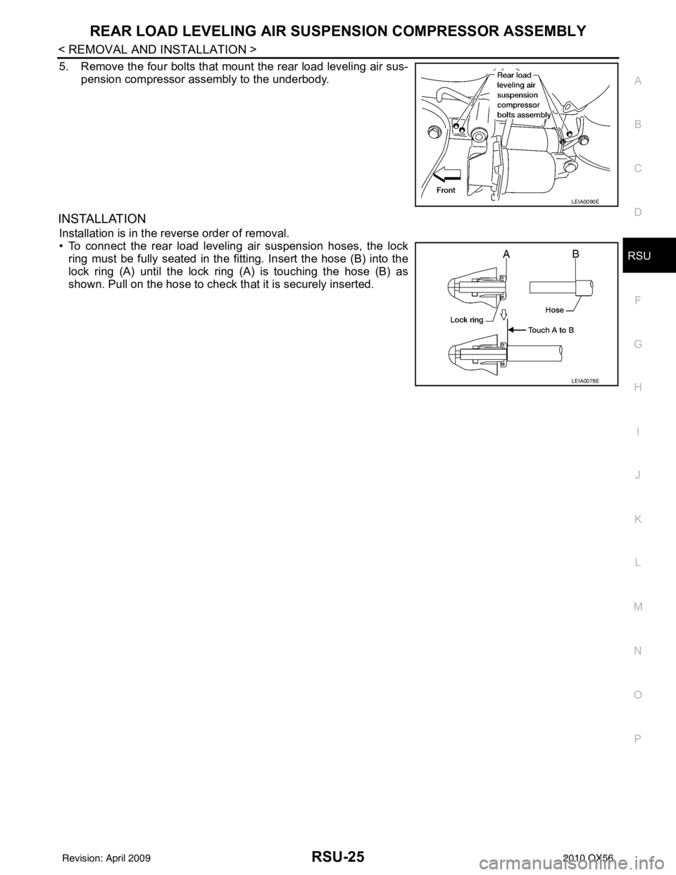
5. Remove the four bolts that mount the rear load leveling air sus- pension compressor assembly to the underbody.
INSTALLATION
Installation is in the reverse order of removal.
• To connect the rear load leveling air suspension hoses, the lockring must be fully seated in the fitt ing. Insert the hose (B) into the
lock ring (A) until the lock ring (A) is touching the hose (B) as
shown. Pull on the hose to check that it is securely inserted.
LEIA0090E
LEIA0078E
Revision: April 20092010 QX56