2010 INFINITI QX56 roof
[x] Cancel search: roofPage 3184 of 4210
RF-56
< ON-VEHICLE REPAIR >
SUNROOF SYSTEM
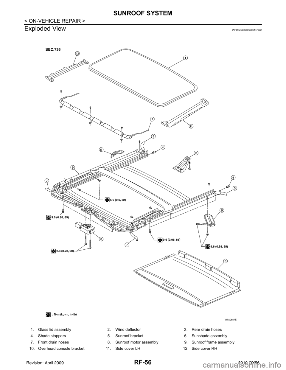
Exploded View
INFOID:0000000005147308
1. Glass lid assembly 2. Wind deflector3. Rear drain hoses
4. Shade stoppers 5. Sunroof bracket 6. Sunshade assembly
7. Front drain hoses 8. Sunroof motor assembly9. Sunroof frame assembly
10. Overhead console bracket 11. Side cover LH 12. Side cover RH
WIIA0657E
Revision: April 20092010 QX56
Page 3185 of 4210
SUNROOF SYSTEMRF-57
< ON-VEHICLE REPAIR >
C
DE
F
G H
I
J
L
M A
B
RF
N
O P
CAUTION:
• Before removal, fully close the glass lid assembly. Then, after removal, do not move the motor
assembly.
• After installing or adjusting the sunroof and glass lid, check gap alignment and sunroof operation to
prevent malfunction.
• Handle glass lid with care so not to cause damage.
Removal and InstallationINFOID:0000000005147309
CAUTION:
• Always work with a helper.
• When taking sunroof unit out, use shop cloths to protect the seats and trim from damage.
• After installing the sunroof unit or glass lid, be sure to check gap adjustment to prevent any mal-
function.
SUNROOF FRAME ASSEMBLY
NOTE:
• For easier installation, mark each point before removal.
Removal
1. Remove headlining. Refer to INT-17, "Removal and Installation".
2. Remove the glass lid assembly. Follow the procedure for GLASS LID ASSEMBLY within this section.
3. Remove overhead console bracket.
4. Disconnect the front and rear drain hoses.
5. Remove front sunroof frame assembly bolts.
6. Remove sunroof frame assembly brackets.
7. Remove the side bolts and the sunroof frame assembly.
8. Remove the sunshade assembly as necessary. Fo llow the procedure for SUNSHADE ASSEMBLY within
this section.
Installation
1. Install the sunshade assembly.
2. Position the sunroof frame assembly and install the side bolts.
3. Install the sunroof brackets.
4. Install the front sunroof frame assembly bolts.
5. Connect front and rear drain hoses.
6. Install the overhead console bracket.
7. Install the glass lid assembly. Follow the procedure for GLASS LID ASSEMBLY within this section.
8. Install headlining. Refer to INT-17, "
Removal and Installation".
9. Perform initialization procedure. Refer to RF-5, "
ADDITIONAL SERVICE WHEN REPLACING CONTROL
UNIT : Special Repair Requirement".
GLASS LID ASSEMBLY
Removal
1. Open sunshade assembly.
2. Ensure glass lid assembly is closed.
3. Remove side cover LH and RH.
Revision: April 20092010 QX56
Page 3186 of 4210
RF-58
< ON-VEHICLE REPAIR >
SUNROOF SYSTEM
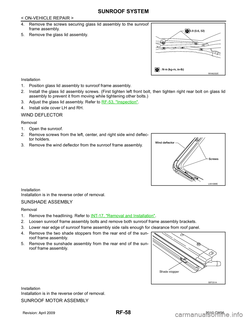
4. Remove the screws securing glass lid assembly to the sunroofframe assembly.
5. Remove the glass lid assembly.
Installation
1. Position glass lid assembly to sunroof frame assembly.
2. Install the glass lid assembly screws. (First tighten left front bolt, then tighten right rear bolt on glass lid
assembly to prevent it from moving while tightening other bolts.)
3. Adjust the glass lid assembly. Refer to RF-53, "
Inspection".
4. Install side cover LH and RH.
WIND DEFLECTOR
Removal
1. Open the sunroof.
2. Remove screws from the left, center, and right side wind deflec- tor holders.
3. Remove the wind deflector from the sunroof frame assembly.
Installation
Installation is in the reverse order of removal.
SUNSHADE ASSEMBLY
Removal
1. Remove the headlining. Refer to INT-17, "Removal and Installation".
2. Loosen sunroof frame assembly bolts and remove both sunroof frame assembly brackets.
3. Lower rear edge of sunroof frame assembly side rails enough for clearance from roof panel.
4. Remove the two shade stoppers from the rear end of the sun- roof frame assembly.
5. Remove the sunshade assembly from the rear end of the sun- roof frame assembly.
Installation
Installation is in the reverse order of removal.
SUNROOF MOTOR ASSEMBLY
WIIA0252E
LIIA1099E
SBT251A
Revision: April 20092010 QX56
Page 3187 of 4210
SUNROOF SYSTEMRF-59
< ON-VEHICLE REPAIR >
C
DE
F
G H
I
J
L
M A
B
RF
N
O P
Removal
CAUTION:
• When removing the sunroof motor, be sure to
place the link and wire assembly in the symmetrical
and fully closed position.
• Never run the removed sunroof motor assembly as a single unit.
1. Position the sunroof in the fully closed position.
2. Remove the roof console assembly. Refer to INT-17, "
Removal and Installation".
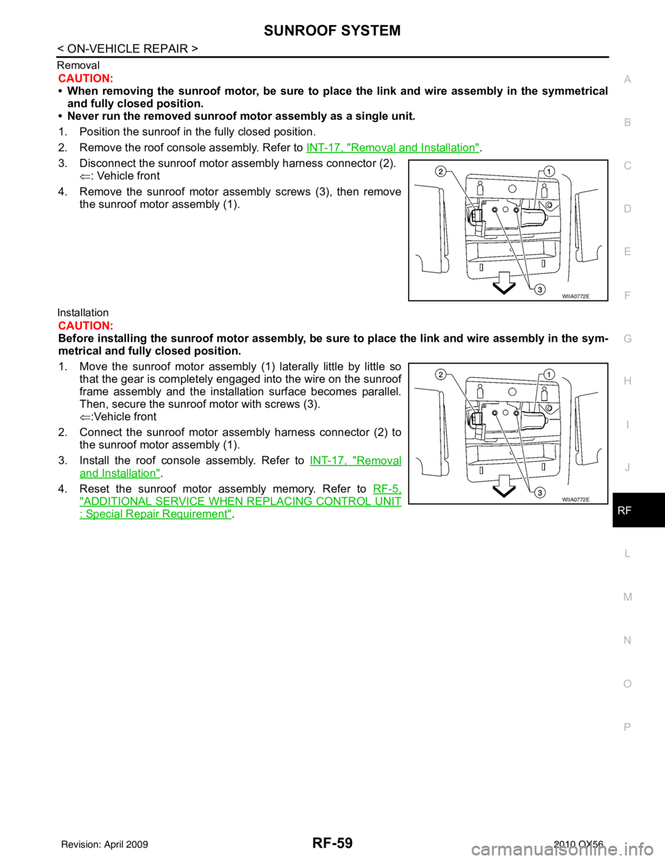
3. Disconnect the sunroof motor assembly harness connector (2). ⇐: Vehicle front
4. Remove the sunroof motor assembly screws (3), then remove the sunroof motor assembly (1).
Installation
CAUTION:
Before installing the sunroof motor assembly, be sure to place the link and wire assembly in the sym-
metrical and fully closed position.
1. Move the sunroof motor assembly (1) laterally little by little so
that the gear is completely engaged into the wire on the sunroof
frame assembly and the installation surface becomes parallel.
Then, secure the sunroof motor with screws (3).
⇐:Vehicle front
2. Connect the sunroof motor assembly harness connector (2) to the sunroof motor assembly (1).
3. Install the roof console assembly. Refer to INT-17, "
Removal
and Installation".
4. Reset the sunroof motor assembly memory. Refer to RF-5,
"ADDITIONAL SERVICE WHEN REPLACING CONTROL UNIT
: Special Repair Requirement".
WIIA0772E
WIIA0772E
Revision: April 20092010 QX56
Page 3227 of 4210
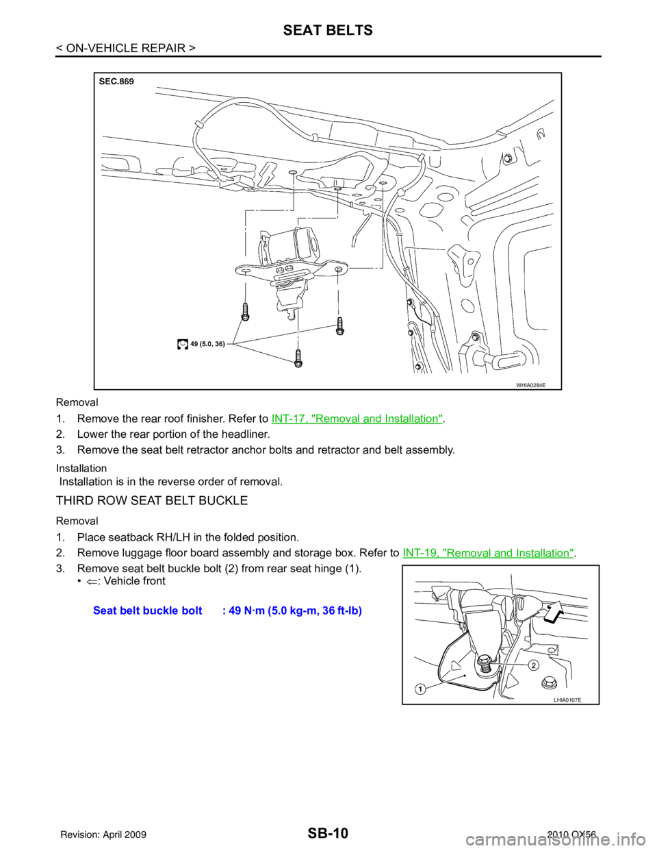
SB-10
< ON-VEHICLE REPAIR >
SEAT BELTS
Removal
1. Remove the rear roof finisher. Refer to INT-17, "Removal and Installation".
2. Lower the rear portion of the headliner.
3. Remove the seat belt retractor anchor bolts and retractor and belt assembly.
Installation
Installation is in the reverse order of removal.
THIRD ROW SEAT BELT BUCKLE
Removal
1. Place seatback RH/LH in the folded position.
2. Remove luggage floor board assembly and storage box. Refer to INT-19, "
Removal and Installation".
3. Remove seat belt buckle bolt (2) from rear seat hinge (1). •⇐ : Vehicle front
WHIA0284E
Seat belt buckle bolt : 49 N·m (5.0 kg-m, 36 ft-lb)
LHIA0107E
Revision: April 20092010 QX56
Page 3314 of 4210
SE-42
< SYMPTOM DIAGNOSIS >
SQUEAK AND RATTLE TROUBLE DIAGNOSES
Most of these incidents can be repaired by adjusting, securing or insulating the item(s) or component(s) caus-
ing the noise.
SUNROOF/HEADLINING
Noises in the sunroof/headlining area c an often be traced to one of the following:
1. Sunroof lid, rail, linkage or seals making a rattle or light knocking noise
2. Sun visor shaft shaking in the holder
3. Front or rear windshield touching headliner and squeaking
Again, pressing on the components to stop the noise while duplicating the conditions can isolate most of these
incidents. Repairs usually consist of insulating with felt cloth tape.
OVERHEAD CONSOLE (FRONT AND REAR)
Overhead console noises are often caused by the c onsole panel clips not being engaged correctly. Most of
these incidents are repaired by pushing up on the c onsole at the clip locations until the clips engage.
In addition look for:
1. Loose harness or harness connectors.
2. Front console map/reading lamp lense loose.
3. Loose screws at console attachment points.
SEATS
When isolating seat noise it's important to note the pos ition the seat is in and the load placed on the seat when
the noise is present. These conditions should be duplicated when verifying and isolating the cause of the
noise.
Cause of seat noise include:
1. Headrest rods and holder
2. A squeak between the seat pad cushion and frame
3. The rear seatback lock and bracket
These noises can be isolated by moving or pressing on the suspected components while duplicating the con-
ditions under which the noise occurs. Most of thes e incidents can be repaired by repositioning the component
or applying urethane tape to the contact area.
UNDERHOOD
Some interior noise may be caused by components under the hood or on the engine wall. The noise is then
transmitted into the passenger compartment.
Causes of transmitted underhood noise include:
1. Any component mounted to the engine wall
2. Components that pass through the engine wall
3. Engine wall mounts and connectors
4. Loose radiator mounting pins
5. Hood bumpers out of adjustment
6. Hood striker out of adjustment
These noises can be difficult to isolate since they cannot be reached from the interior of the vehicle. The best
method is to secure, move or insulate one component at a time and test drive the \
vehicle. Also, engine RPM
or load can be changed to isolate the noise. Repairs can usually be made by moving, adjusting, securing, or
insulating the component causing the noise.
Revision: April 20092010 QX56
Page 3352 of 4210
SEC-1
BODY EXTERIOR, DOORS, ROOF & VEHICLE SECURITY
C
DE
F
G H
I
J
L
M
SECTION SEC
A
B
SEC
N
O P
CONTENTS
SECURITY CONTROL SYSTEM
WITH INTELLIGENT KEY SYSTEM
BASIC INSPECTION ....... .............................
4
DIAGNOSIS AND REPAIR WORKFLOW ..... .....4
Work Flow ........................................................... ......4
PRE-INSPECTION FOR DIAGNOSTIC ..............7
Basic Inspection .................................................. ......7
Vehicle Security Operation Check ............................7
INSPECTION AND ADJUSTMENT .....................9
ADDITIONAL SERVICE WHEN REPLACING
CONTROL UNIT .................................................... ......
9
ADDITIONAL SERVICE WHEN REPLACING
CONTROL UNIT : Special Repair Requirement .......
9
ECM RE-COMMUNICATING FUNCTION ............. ......9
ECM RE-COMMUNICATING FUNCTION : De-
scription .....................................................................
9
ECM RE-COMMUNICATING FUNCTION : Spe-
cial Repair Requirement ............................................
9
FUNCTION DIAGNOSIS ..............................10
INTELLIGENT KEY SYSTEM/ENGINE
START FUNCTIO N ........................................ ....
10
System Diagram .................................................. ....10
System Description .................................................10
Component Parts Location ......................................12
Component Description ...........................................13
INFINITI VEHICLE IMMOBILIZER SYSTEM-
NATS ..................................................................
14
System Diagram .................................................. ....14
System Description .................................................14
Component Parts Location ......................................16
Component Description ..........................................16
VEHICLE SECURITY SYSTEM .........................18
System Diagram .................................................. ....18
System Description .................................................18
Component Parts Location .................................. ....19
Component Description ...........................................20
DIAGNOSIS SYSTEM (BCM) ...........................21
COMMON ITEM ..................................................... ....21
COMMON ITEM : CONSULT-III Function (BCM -
COMMON ITEM) .....................................................
21
IMMU ...................................................................... ....21
IMMU : CONSULT-III Function (BCM - IMMU) ........22
THEFT ALM ........................................................... ....22
THEFT ALM : CONSULT-III Function (BCM -
THEFT ALM) ....................................................... ....
22
DIAGNOSIS SYSTEM (INTELLIGENT KEY
UNIT) .................................................................
24
CONSULT-III Function (INTELLIGENT KEY) ..........24
COMPONENT DIAGNOSIS .........................26
U1000 CAN COMM CIRCUIT ...........................26
Description ........................................................... ....26
DTC Logic ................................................................26
Diagnosis Procedure ...............................................26
U1010 CONTROL UNIT (CAN) .........................27
Description ...............................................................27
DTC Logic ................................................................27
Diagnosis Procedure ...............................................27
Special Repair Requirement ....................................27
B2013 ID DISCORD I-KEY-STRG ....................28
Description ...............................................................28
DTC Logic ................................................................28
Diagnosis Procedure ...............................................28
B2190 NATS ANTENNA AMP. .........................31
Description ...............................................................31
DTC Logic ................................................................31
Diagnosis Procedure ...............................................31
Revision: April 20092010 QX56
Page 3376 of 4210
![INFINITI QX56 2010 Factory Service Manual DIAGNOSIS SYSTEM (INTELLIGENT KEY UNIT)SEC-25
< FUNCTION DIAGNOSIS > [WITH INTELLIGENT KEY SYSTEM]
C
D
E
F
G H
I
J
L
M A
B
SEC
N
O P
ACTIVE TEST
TRUNK SW This item is shown but not monitored.
VEHICLE INFINITI QX56 2010 Factory Service Manual DIAGNOSIS SYSTEM (INTELLIGENT KEY UNIT)SEC-25
< FUNCTION DIAGNOSIS > [WITH INTELLIGENT KEY SYSTEM]
C
D
E
F
G H
I
J
L
M A
B
SEC
N
O P
ACTIVE TEST
TRUNK SW This item is shown but not monitored.
VEHICLE](/manual-img/42/57032/w960_57032-3375.png)
DIAGNOSIS SYSTEM (INTELLIGENT KEY UNIT)SEC-25
< FUNCTION DIAGNOSIS > [WITH INTELLIGENT KEY SYSTEM]
C
D
E
F
G H
I
J
L
M A
B
SEC
N
O P
ACTIVE TEST
TRUNK SW This item is shown but not monitored.
VEHICLE SPEED Displays the vehicle speed signal received from combination meter by numerical value
[km/h].
Monitor Item
Condition
Test itemDescription
DOOR LOCK/UNLOCK This test is able to check door lock/unlock operation.
• ALL UNLK: All door lock actuators are unlocked.
• DR UNLK: Door lock actuator
(driver side) is unlocked.
• AS UNLK: Door lock actuator (passenger side) is unlocked.
• BK UNLK: This item is indicated, but inactive.
• LOCK: All door lock actuator is locked.
ANTENNA This test is able to check Intelligent Key antenna operation.
When the following condition are met, hazard warning lamps flash.
• ROOM ANT1: Inside key antenna (front of center console) detects Intelligent Key,
when “ROOM ANT1” is selected.
• ROOM ANT2: Inside key antenna (rear luggage area) detects Intelligent Key, when “ROOM ANT2”is selected.
• ROOM ANT3: Inside key antenna (rear of center console) detects Intelligent Key,
when “ROOM ANT3” is selected.
• ROOM ANT4: Inside key antenna (roof console) detects Intelligent Key, when “ROOM ANT4”is selected.
• DRIVER ANT: Outside key antenna (driver side) detects Intelligent Key, when “DRIV- ER ANT” is selected.
• ASSIST ANT: Outside key antenna (passenger side) detects Intelligent Key, when
“ASSIST ANT” is selected.
• BK DOOR ANT: Outside key antenna (rear bumper) detects Intelligent Key, when “BK DOOR ANT” is selected.
OUTSIDE BUZZER This test is able to check Intelligent Key warning buzzer operation.
•ON
•OFF
INSIDE BUZZER This test is able to check warning chime in combination meter operation.
• TAKE OUT: Take away
warning chime sounds.
• KNOB: Ignition knob switch warning chime sounds.
• KEY: Key warning chime sounds.
•OFF
Revision: April 20092010 QX56