Page 3852 of 4210
LINE PRESSURE TESTTM-157
< ON-VEHICLE MAINTENANCE >
CEF
G H
I
J
K L
M A
B
TM
N
O P
LINE PRESSURE TEST
Inspection and JudgmentINFOID:0000000005148727
LINE PRESSURE TEST
Line Pressure Test Port
Line Pressure Test Procedure
1. Inspect the amount of engine oil and replenish if necessary.
2. Drive the car for about 10 minutes to warm it up so that the ATF reaches in range of 50 to 80 °C (122 to
176° F), then inspect the amount of ATF and replenish if necessary.
NOTE:
The automatic fluid temperature rises in range of 50 to 80 °C (122 to 176° F) during 10 minutes of
driving.
3. After warming up remove the oil pressure detection plug and install the Tool.
CAUTION:
When using the oil pressure ga uge, be sure to use the O-
ring attached to the oil pressure detection plug.
4. Securely engage the parking brake so that the tires do not turn.
SCIA2187E
SCIA5309E
SCIA1224E
Revision: April 20092010 QX56
Page 3853 of 4210

TM-158
< ON-VEHICLE MAINTENANCE >
LINE PRESSURE TEST
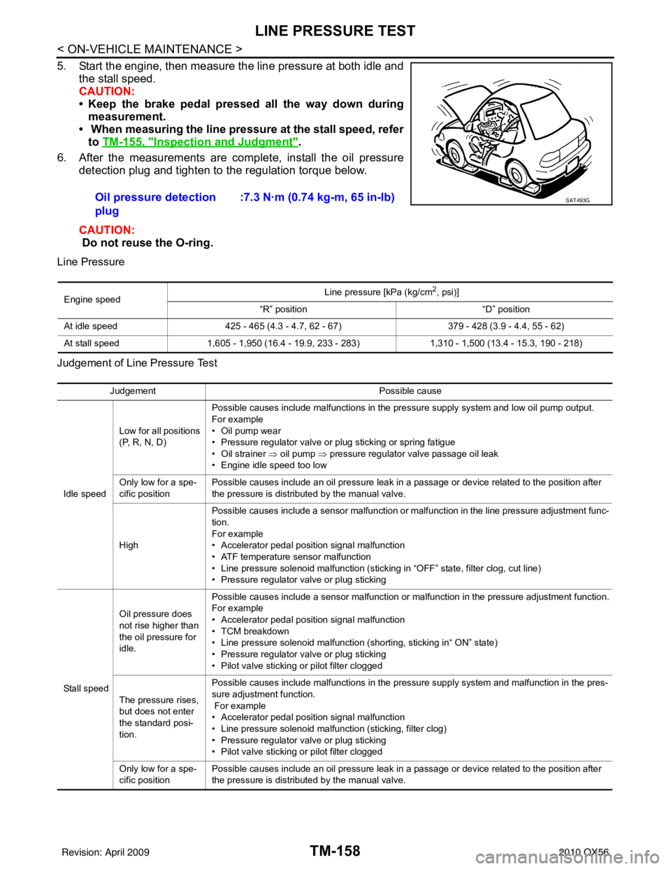
5. Start the engine, then measure the line pressure at both idle andthe stall speed.
CAUTION:
• Keep the brake pedal pressed all the way down duringmeasurement.
• When measuring the line pressure at the stall speed, refer
to TM-155, "
Inspection and Judgment".
6. After the measurements are complete, install the oil pressure detection plug and tighten to the regulation torque below.
CAUTION:
Do not reuse the O-ring.
Line Pressure
Judgement of Line Pressure Test
Oil pressure detection
plug :7.3 N·m (0.74 kg-m, 65 in-lb)SAT493G
Engine speed
Line pressure [kPa (kg/cm
2, psi)]
“R” position “D” position
At idle speed 425 - 465 (4.3 - 4.7, 62 - 67) 379 - 428 (3.9 - 4.4, 55 - 62)
At stall speed 1,605 - 1,950 (16.4 - 19.9, 233 - 283) 1,310 - 1,500 (13.4 - 15.3, 190 - 218)
Judgement Possible cause
Idle speed Low for all positions
(P, R, N, D)
Possible causes include malfunctions in the pressure supply system and low oil pump output.
For example
•Oil pump wear
• Pressure regulator valve or plug sticking or spring fatigue
• Oil strainer ⇒ oil pump
⇒ pressure regulator valve passage oil leak
• Engine idle speed too low
Only low for a spe-
cific position Possible causes include an oil pressure leak in a passage or device related to the position after
the pressure is distributed by the manual valve.
High Possible causes include a sensor malfunction or malfunction in the line pressure adjustment func-
tion.
For example
• Accelerator pedal position signal malfunction
• ATF temperature sensor malfunction
• Line pressure solenoid malfunction (sticking in “OFF” state, filter clog, cut line)
• Pressure regulator valve or plug sticking
Sta ll sp ee d Oil pressure does
not rise higher than
the oil pressure for
idle.
Possible causes include a sensor malfunction or malfunction in the pressure adjustment function.
For example
• Accelerator pedal position signal malfunction
• TCM breakdown
• Line pressure solenoid malfunction (shorting, sticking in“ ON” state)
• Pressure regulator valve or plug sticking
• Pilot valve sticking or pilot filter clogged
The pressure rises,
but does not enter
the standard posi-
tion. Possible causes include malfunctions in the pressure supply system and malfunction in the pres-
sure adjustment function.
For example
• Accelerator pedal position signal malfunction
• Line pressure solenoid malfunction (sticking, filter clog)
• Pressure regulator valve or plug sticking
• Pilot valve sticking or pilot filter clogged
Only low for a spe-
cific position Possible causes include an oil pressure leak in a passage or device related to the position after
the pressure is distributed by the manual valve.
Revision: April 20092010 QX56
Page 3855 of 4210

TM-160
< ON-VEHICLE MAINTENANCE >
ROAD TEST
YES >> Record the malfunction, GO TO 4.
NO >> GO TO 4.
4.CHECK “N” POSITION FUNCTIONS
1. Start the engine.
2. Move selector lever to “N” position.
3. Release the parking brake.
Does vehicle move forward or backward?
YES >> Record the malfunction, GO TO 5.
NO >> GO TO 5.
5.CHECK SHIFT SHOCK
1. Engage the brake.
2. Move selector lever to “D” position.
When the transmission is shifted from
“N” to “D”, is there an excessive shock?
YES >> Record the malfunction, GO TO 6.
NO >> GO TO 6.
6.CHECK “R” POSITION FUNCTIONS
1. Engage the brake.
2. Move selector lever to “R” position.
3. Release the brake for 4 to 5 seconds.
Does the vehicle creep backward?
YES >> GO TO 7.
NO >> Record the malfunction, GO TO 7.
7.CHECK “D” POSITION FUNCTIONS
Inspect whether the vehicle creeps forward when the transmission is put into the “D” position.
Does the vehicle creep forward in the
“D” positions?
YES >> Go to TM-160, "Cruise Test - Part 1".
NO >> Record the malfunction and go to TM-160, "
Cruise Test - Part 1".
Cruise Test - Part 1INFOID:0000000005148731
1.CHECK STARTING OUT FROM D1
1. Drive the vehicle for about 10 minutes to warm up the engine oil and ATF. Appropriate temperature for the ATF: 50 - 80° C (122 - 176°F)
2. Park the vehicle on a level surface.
3. Move selector lever to “P” position.
4. Start the engine.
5. Move selector lever to “D” position.
6. Press the accelerator pedal about half way down to accelerate the vehicle.
With CONSULT-III
Read off the gear positions.
Starts from D1?
YES >> GO TO 2.
NO >> Record the malfunction, GO TO 2.
2.CHECK SHIFT-UP D1 → D2
Press down the accelerator pedal about half way and inspect if the vehicle shifts up (D1 → D2) at the appropri-
ate speed.
• Refer to TM-265, "
Vehicle Speed at Which Gear Shifting Occurs".
With CONSULT-III
Read the gear position, throttle degree of opening, and vehicle speed.
Does the A/T shift-up D1
→ D2 at the correct speed?
YES >> GO TO 3.
NO >> Record the malfunction, GO TO 3.
Revision: April 20092010 QX56
Page 3867 of 4210
TM-172
< ON-VEHICLE REPAIR >
CONTROL VALVE WITH TCM
CONTROL VALVE WITH TCM
Control Valve with TCM and A/T Fluid Temperature Sensor 2 and PlugINFOID:0000000005148741
COMPONENTS
CONTROL VALVE WITH TCM REMOVAL AND INSTALLATION
Removal
1. Disconnect negative battery terminal.
2. Drain A/T fluid. Refer to TM-150, "
Changing the A/T Fluid (ATF)".
3. Disconnect A/T assembly harness connector.
1. Transmission 2. Snap ring3. Sub-harness
4. Control valve with TCM 5. Bracket 6. A/T fluid temperature sensor 2
7. Oil pan gasket 8. Brackets9. Oil pan bolt
10. Oil pan 11. Magnet12. Drain plug
13. Drain plug gasket 14. Terminal cord assembly 15. O-ring
16. O-ring 17. Plug
A/T fluid temperature sensor 2 (A) can be changed to plug (B), depending on vehicles.
JSDIA1314GB
Revision: April 20092010 QX56
Page 3868 of 4210
CONTROL VALVE WITH TCMTM-173
< ON-VEHICLE REPAIR >
CEF
G H
I
J
K L
M A
B
TM
N
O P
4. Remove snap ring from A/T assembly harness connector.
5. Push A/T assembly harness connector. CAUTION:
Do not damage connector.
6. Remove oil pan and oil pan gasket. Refer to TM-170, "
Oil Pan".
7. If an A/T fluid temperature sensor 2 is attached, disconnect the A/T fluid temperature sensor 2 connector
as shown below.
a. Disconnect A/T fluid temperat ure sensor 2 connector (A).
CAUTION:
Do not damage connector.
b. Straighten the four terminal clips ( ) to free the terminal cord assembly for A/T fluid temperature sensor 2 harness.
8. Straighten terminal clip ( ) to free the output speed sensor har- ness.
9. Disconnect output speed sensor connector (1). CAUTION:
Do not damage connector.
SCIA5021E
SCIA5022E
SCIA8124E
JSDIA1316ZZ
Revision: April 20092010 QX56
Page 3875 of 4210
TM-180
< ON-VEHICLE REPAIR >
CONTROL VALVE WITH TCM
12. Securely fasten output speed sensor (1) harness with terminalclip ( ).
13. Install oil pan to transmission case. Refer to TM-170, "
Oil Pan".
14. Pull up A/T assembly harness connector. CAUTION:
Do not damage connector.
15. Install snap ring to A/T assembly harness connector.
16. Connect A/T assembly harness connector.
17. Connect the negative battery terminal.
18. Refill the A/T with fluid and check the fluid level and for fluid leakage. Refer to TM-148, "
Checking the A/T Fluid (ATF)".
REMOVAL AND INSTALLATION OF A/T FLUID TEMPERATURE SENSOR 2
Removal
1. Disconnect negative battery terminal.
2. Remove oil pan and oil pan gasket. Refer to TM-170, "
Oil Pan".
3. Disconnect A/T fluid temperat ure sensor 2 connector (A).
CAUTION:
Do not damage connector.
4. Straighten terminal clip ( ) to free A/T fluid temperature sensor 2 harness.
JSDIA1316ZZ
SCIA5038E
SCIA5039E
SCIA8125E
Revision: April 20092010 QX56
Page 3877 of 4210
TM-182
< ON-VEHICLE REPAIR >
CONTROL VALVE WITH TCM
3. Connect A/T fluid temperature sensor 2 connector (A).
4. Securely fasten A/T fluid temperature sensor 2 harness with ter-minal clip .
5. Install oil pan to transmission case. Refer to TM-170, "
Oil Pan".
6. Connect the negative battery terminal.
7. Refill the A/T with fluid and check the fluid level and for fluid leakage. Refer to TM-148, "
Checking the A/T
Fluid (ATF)".
REMOVAL AND INSTALLATION OF PLUG
Removal
1. Disconnect negative battery terminal.
2. Remove oil pan and oil pan gasket. Refer to TM-170, "
Oil Pan".
3. Remove plug (1) with bracket (2) from control valve with TCM.
4. Remove bracket (1) from plug (2).
5. Remove O-ring (1) from plug (2).
Installation
CAUTION:
SCIA8125E
: Bolt
JSDIA1311ZZ
JSDIA1312ZZ
JSDIA1313ZZ
Revision: April 20092010 QX56
Page 3891 of 4210
TM-196
< DISASSEMBLY AND ASSEMBLY >
OVERHAUL
4WD
16. Bearing race17. Needle bearing18. Manual plate
19. Parking rod 20. Manual shaft oil seal 21. Manual shaft
22. O-ring 23. Band servo anchor end pin 24. Detent spring
25. Spacer 26. Seal ring27. Snap ring
28. Return spring 29. O-ring30. Servo assembly
31. Snap ring 32. Sub-harness33. Control valve with TCM
34. Bracket 35. A/T fluid temperature sensor 2 36. Oil pan gasket
37. Brackets 38. Oil pan bolt39. Oil pan
40. Magnets 41. Drain plug42. Drain plug gasket
43. A/T assemblt harness connector 44. O-ring 45. Retaining pin
46. Transmission case 47. O-ring48. Plug
A/T fluid temperature sensor 2 (A) can be changed to plug (B), depending on vehicles.
*: Apply Genuine Anaerobic Liquid Gasket or equivalent.
Revision: April 20092010 QX56