2010 INFINITI QX56 oil temperature
[x] Cancel search: oil temperaturePage 3457 of 4210
![INFINITI QX56 2010 Factory Service Manual SEC-106
< ECU DIAGNOSIS >[WITH INTELLIGENT KEY SYSTEM]
IPDM E/R (INTELLIGENT POWER DI
STRIBUTION MODULE ENGINE ROOM)
IPDM E/R (INTELLIGENT POWER DISTRIBUTION MODULE ENGINE
ROOM)
Reference ValueINFOID INFINITI QX56 2010 Factory Service Manual SEC-106
< ECU DIAGNOSIS >[WITH INTELLIGENT KEY SYSTEM]
IPDM E/R (INTELLIGENT POWER DI
STRIBUTION MODULE ENGINE ROOM)
IPDM E/R (INTELLIGENT POWER DISTRIBUTION MODULE ENGINE
ROOM)
Reference ValueINFOID](/manual-img/42/57032/w960_57032-3456.png)
SEC-106
< ECU DIAGNOSIS >[WITH INTELLIGENT KEY SYSTEM]
IPDM E/R (INTELLIGENT POWER DI
STRIBUTION MODULE ENGINE ROOM)
IPDM E/R (INTELLIGENT POWER DISTRIBUTION MODULE ENGINE
ROOM)
Reference ValueINFOID:0000000005282717
VALUES ON THE DIAGNOSIS TOOL
Monitor Item ConditionValue/Status
MOTOR FAN REQ Engine idle speed Changes depending on engine
coolant temperature, air conditioner
operation status, vehicle speed,
etc.0 - 100 %
A/C COMP REQ A/C switch OFF
OFF
A/C switch ON ON
TAIL&CLR REQ Lighting switch OFF
OFF
Lighting switch 1ST, 2ND, HI or AUTO (Light is illuminated) ON
HL LO REQ Lighting switch OFF
OFF
Lighting switch 2ND HI or AUTO (Light is illuminated) ON
HL HI REQ Lighting switch OFF
OFF
Lighting switch HI ON
FR FOG REQ Lighting switch 2ND or AUTO (Light
is illuminated) Front fog lamp switch OFF OFF
• Front fog lamp switch ON
• Daytime light activated (Canada
only) ON
FR WIP REQ Ignition switch ON Front wiper switch OFF
STOP
Front wiper switch INT 1LOW
Front wiper switch LO LOW
Front wiper switch HI HI
WIP AUTO STOP Ignition switch ON Front wiper stop position
STOP P
Any position other than front wiper
stop position ACT P
WIP PROT Ignition switch ON Front wiper operates normally OFF
Front wiper stops at fail-safe opera-
tion
BLOCK
ST RLY REQ Ignition switch OFF or ACC
OFF
Ignition switch START ON
IGN RLY Ignition switch OFF or ACC
OFF
Ignition switch ON ON
RR DEF REQ Rear defogger switch OFF
OFF
Rear defogger switch ON ON
OIL P SW Ignition switch OFF, ACC or engine running
OPEN
Ignition switch ON CLOSE
DTRL REQ Daytime light system requested OFF with CONSULT-III.
OFF
Daytime light system requested ON with CONSULT-III. ON
HOOD SW Hood closed.
OFF
Hood open. ON
Revision: April 20092010 QX56
Page 3536 of 4210
SIDE CURTAIN AIR BAG MODULESR-13
< ON-VEHICLE REPAIR >
C
DE
F
G
I
J
K L
M A
B
SR
N
O P
SIDE CURTAIN AIR BAG MODULE
Removal and InstallationINFOID:0000000005147760
REMOVAL
CAUTION:
• Do not attempt to repair or replace damaged direct-connect SRS component connectors. If a direct- connect harness connector is damage d, the harness must be replaced.
• Before servicing the SRS, turn the ignition switch off, disconnect both battery terminals and wait at
least three minutes.
• When servicing the SRS, do not work from directly in front of air bag module.
• Do not insert any foreign objects (screwdriver, etc.) into air bag module or harness connectors.
• Do not disassemble air bag module.
• Do not expose the air bag modu le to temperatures exceeding 90°C (194 °F).
• Replace side curtain air bag modu le if it has been dropped or
sustained an impact.
• Do not allow oil, grease or water to come in contact with the
air bag module.
1. Disconnect both the negative and positive battey terminals, then wait at least three minutes.
2. Remove headlining. Refer to INT-17, "
Removal and Installation".
3. Disconnect front and rear side curtain air bag module connec- tors.
• For removal/installation of the direct-connect SRS connectors,
refer to SRC-9, "
Direct-connect SRS Component Connectors".
4. Remove the bolts in order starting at the front or rear, and remove the side curtain air bag module.
INSTALLATION
Installation is in the reverse order of removal.
• For removal/installation of the direct-connect SRS connectors, refer to SRC-9, "
Direct-connect SRS Compo-
nent Connectors".
• After replacement of side curtain air bag module, per form self-diagnosis to check that no malfunction is
detected. Refer to SRC-13, "
SRS Operation Check".
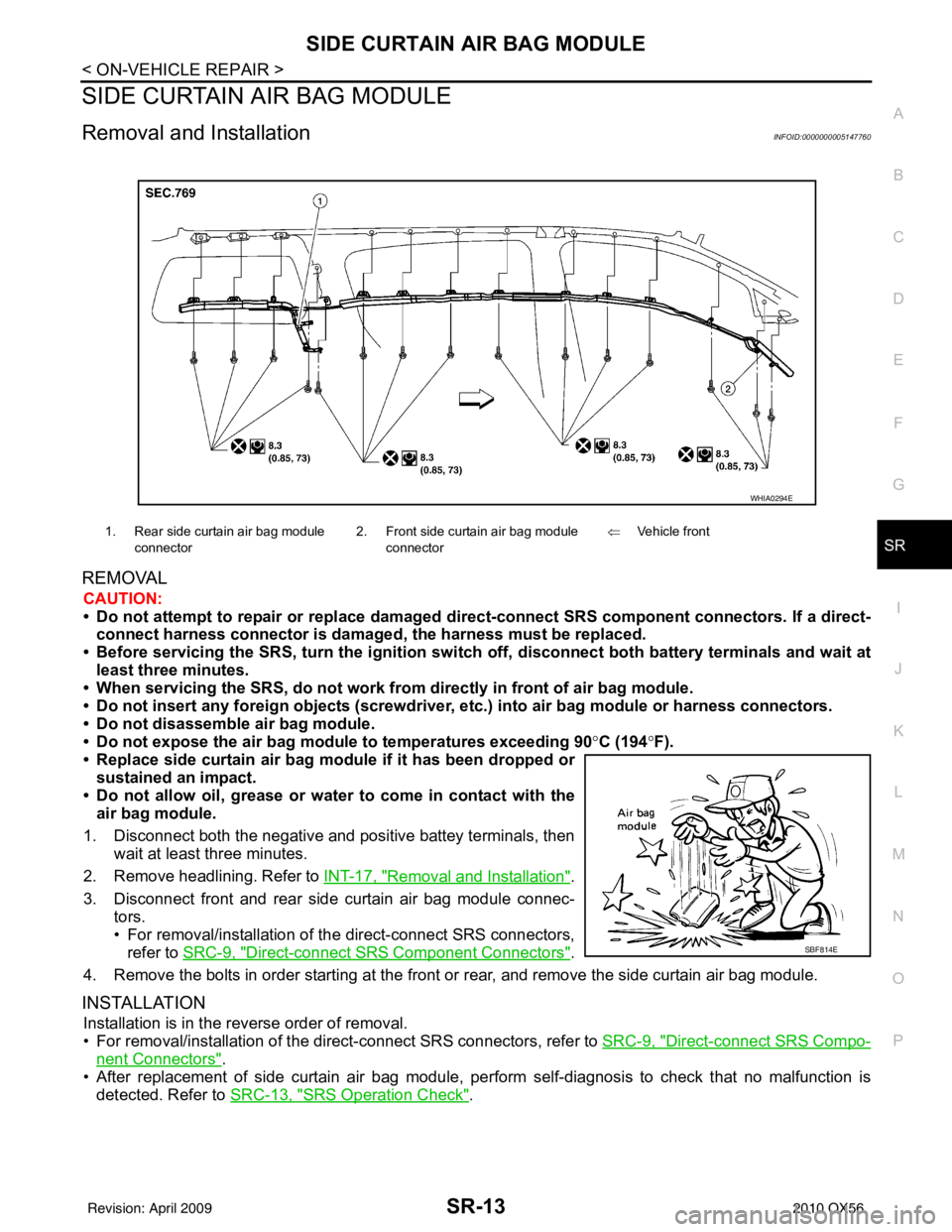
1. Rear side curtain air bag module
connector 2. Front side curtain air bag module
connector ⇐
Vehicle front
WHIA0294E
SBF814E
Revision: April 20092010 QX56
Page 3651 of 4210
POWER STEERING FLUIDST-13
< ON-VEHICLE MAINTENANCE >
C
DE
F
H I
J
K L
M A
B
ST
N
O P
ON-VEHICLE MAINTENANCE
POWER STEERING FLUID
Checking Fluid LevelINFOID:0000000005147865
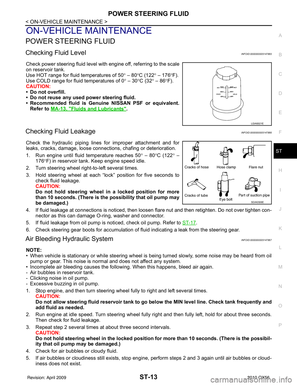
Check power steering fluid level with engine off, referring to the scale
on reservoir tank.
Use HOT range for fluid temperatures of 50 ° – 80 °C (122 ° – 176 °F).
Use COLD range for fluid temperatures of 0 ° – 30 °C (32° – 86°F).
CAUTION:
• Do not overfill.
• Do not reuse any used power steering fluid.
• Recommended fluid is Genuine NISSAN PSF or equivalent. Refer to MA-13, "
Fluids and Lubricants".
Checking Fluid LeakageINFOID:0000000005147866
Check the hydraulic piping lines for improper attachment and for
leaks, cracks, damage, loose connec tions, chafing or deterioration.
1. Run engine until fluid temperature reaches 50 ° – 80° C (122° –
176° F) in reservoir tank. Keep engine speed idle.
2. Turn steering wheel right-to-left several times.
3. Hold steering wheel at each “lock” position for five seconds to check fluid leakage.
CAUTION:
Do not hold steering wheel in a locked position for more
than 10 seconds. (There is the possibility that oil pump may
be damaged.)
4. If fluid leakage at connections is noticed, then loosen flare nut and then retighten. Do not over tighten con- nector as this can damage O-ring, washer and connector.
5. If fluid leakage from oil pump is noticed, check oil pump. Refer to ST-17
.
6. Check steering gear boots for accumulation of fluid indicating a leak from the steering gear.
Air Bleeding Hydraulic SystemINFOID:0000000005147867
NOTE:
• When vehicle is stationary or while steering wheel is being turned slowly, some noise may be heard from oil pump or gear. This noise is normal and does not affect any system.
• Incomplete air bleeding causes the fo llowing. When this happens, bleed air again.
- Air bubbles in reservoir tank.
- Clicking noise in oil pump.
- Excessive buzzing in oil pump.
1. Stop engine, and then turn steering wheel fully to right and left several times. CAUTION:
Do not allow steering fluid reservoir tank to go below the MIN level line. Check tank frequently and
add fluid as needed.
2. Run engine at idle speed. Turn steering wheel fully right and then fully left, hold for about three seconds.
Then check for fluid leakage.
3. Repeat step 2 several times at about three second intervals. CAUTION:
Do not hold steeri ng wheel in the locked position for more than 10 seconds. (There is the possibil-
ity that oil pump may be damaged.)
4. Check for air bubbles or cloudy fluid.
5. If air bubbles or cloudiness still exists, stop engine, perform steps 2 and 3 again until air bubbles or cloud-
iness does not exist.
LGIA0021E
SGIA0506E
Revision: April 20092010 QX56
Page 3655 of 4210
POWER STEERING OIL PUMPST-17
< ON-VEHICLE REPAIR >
C
DE
F
H I
J
K L
M A
B
ST
N
O P
POWER STEERING OIL PUMP
On-Vehicle Inspection and ServiceINFOID:0000000005147869
CHECKING RELIEF OIL PRESSURE
CAUTION:
Before starting work, confirm belt tension is proper.
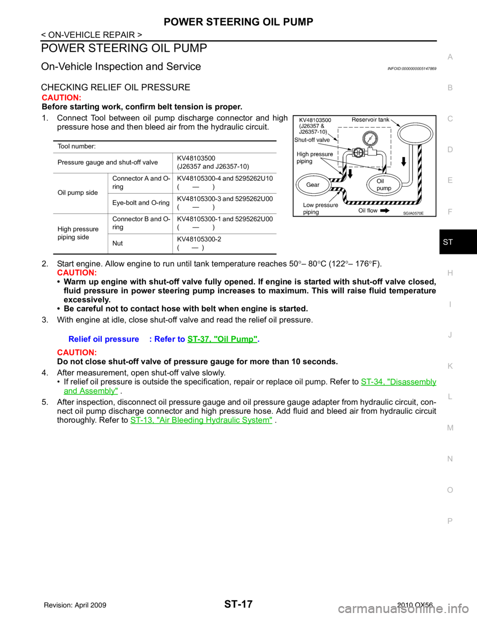
1. Connect Tool between oil pump discharge connector and high pressure hose and then bleed air from the hydraulic circuit.
2. Start engine. Allow engine to run until tank temperature reaches 50 °– 80° C (122° – 176°F).
CAUTION:
• Warm up engine with shut-off valve fully opened. If engine is started with shut-off valve closed,
fluid pressure in power steering pump increases to maximum. This will raise fluid temperature
excessively.
• Be careful not to contact hose with belt when engine is started.
3. With engine at idle, close shut-off valve and read the relief oil pressure.
CAUTION:
Do not close shut-off valve of pressure gauge for more than 10 seconds.
4. After measurement, open shut-off valve slowly. • If relief oil pressure is outside the specification, repair or replace oil pump. Refer to ST-34, "
Disassembly
and Assembly" .
5. After inspection, disconnect oil pressure gauge and oil pressure gauge adapter from hydraulic circuit, con-
nect oil pump discharge connector and high pressure hose. Add fluid and bleed air from hydraulic circuit
thoroughly. Refer to ST-13, "
Air Bleeding Hydraulic System" .
Tool number:
Pressure gauge and shut-off valve KV48103500
(J26357 and J26357-10)
Oil pump side Connector A and O-
ring
KV48105300-4 and 5295262U10
(—)
Eye-bolt and O-ring KV48105300-3 and 5295262U00
(—)
High pressure
piping side Connector B and O-
ring
KV48105300-1 and 5295262U00
(—)
Nut KV48105300-2
( — )
SGIA0570E
Relief oil pressure : Refer to
ST-37, "Oil Pump".
Revision: April 20092010 QX56
Page 3719 of 4210
TM-24
< FUNCTION DIAGNOSIS >
A/T CONTROL SYSTEM
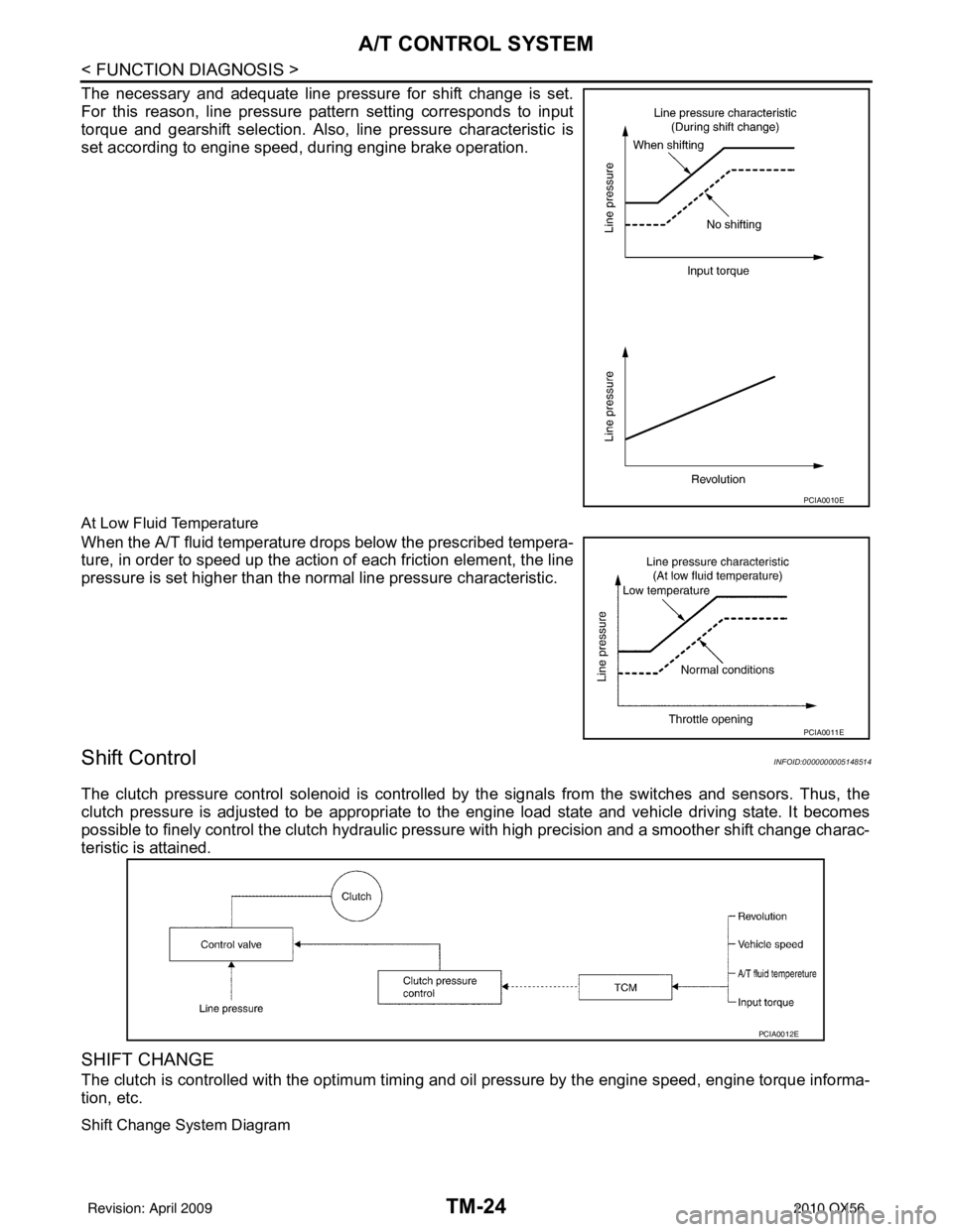
The necessary and adequate line pressure for shift change is set.
For this reason, line pressure pattern setting corresponds to input
torque and gearshift selection. Also, line pressure characteristic is
set according to engine speed, during engine brake operation.
At Low Fluid Temperature
When the A/T fluid temperature drops below the prescribed tempera-
ture, in order to speed up the action of each friction element, the line
pressure is set higher than the normal line pressure characteristic.
Shift ControlINFOID:0000000005148514
The clutch pressure control solenoid is controlled by the signals from the switches and sensors. Thus, the
clutch pressure is adjusted to be appropriate to the engine load state and vehicle driving state. It becomes
possible to finely control the clutch hydraulic pressure with high precision and a smoother shift change charac-
teristic is attained.
SHIFT CHANGE
The clutch is controlled with the optimum timing and oil pressure by the engine speed, engine torque informa-
tion, etc.
Shift Change System Diagram
PCIA0010E
PCIA0011E
PCIA0012E
Revision: April 20092010 QX56
Page 3832 of 4210
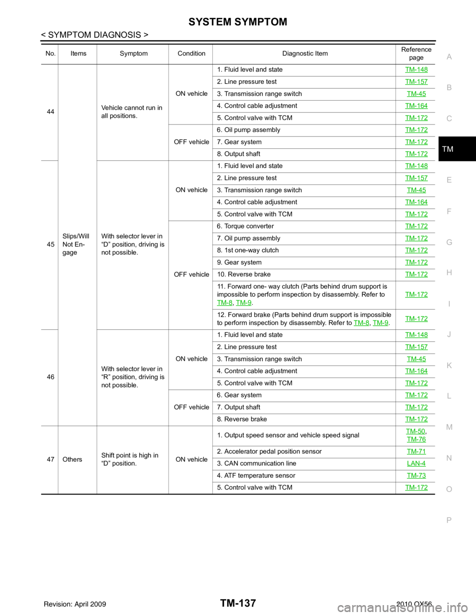
SYSTEM SYMPTOMTM-137
< SYMPTOM DIAGNOSIS >
CEF
G H
I
J
K L
M A
B
TM
N
O P
44
Slips/Will
Not En-
gage Vehicle cannot run in
all positions.
ON vehicle1. Fluid level and state
TM-148
2. Line pressure testTM-157
3. Transmission range switch TM-45
4. Control cable adjustmentTM-164
5. Control valve with TCMTM-172
OFF vehicle6. Oil pump assembly
TM-1727. Gear systemTM-172
8. Output shaftTM-172
45With selector lever in
“D” position, driving is
not possible. ON vehicle
1. Fluid level and state
TM-148
2. Line pressure testTM-157
3. Transmission range switch TM-45
4. Control cable adjustmentTM-164
5. Control valve with TCMTM-172
OFF vehicle6. Torque converter
TM-172
7. Oil pump assembly TM-172
8. 1st one-way clutchTM-172
9. Gear systemTM-172
10. Reverse brakeTM-172
11. Forward one- way clutch (Parts behind drum support is
impossible to perform inspection by disassembly. Refer to
TM-8
, TM-9.TM-172
12. Forward brake (Parts behind drum support is impossible
to perform inspection by disassembly. Refer to
TM-8
, TM-9. TM-172
46 With selector lever in
“R” position, driving is
not possible. ON vehicle
1. Fluid level and state
TM-148
2. Line pressure testTM-157
3. Transmission range switch TM-45
4. Control cable adjustmentTM-164
5. Control valve with TCMTM-172
OFF vehicle6. Gear system
TM-1727. Output shaftTM-172
8. Reverse brakeTM-172
47 OthersShift point is high in
“D” position. ON vehicle1. Output speed sensor and vehicle speed signal
TM-50
,
TM-76
2. Accelerator pedal position sensor TM-71
3. CAN communication line LAN-4
4. ATF temperature sensorTM-73
5. Control valve with TCMTM-172
No. ItemsSymptom Condition Diagnostic ItemReference
page
Revision: April 20092010 QX56
Page 3839 of 4210
TM-144
< PRECAUTION >
PRECAUTIONS
•After performing each TROUBLE DIAGNOSIS, perform “DTC
(Diagnostic Trouble Code) CONFIRMATION PROCEDURE”.
If the repair is completed the DTC should not be displayed in the
“DTC CONFIRMATION PROCEDURE”.
• Always use the specified brand of ATF. Refer to MA-13, "
Fluids and Lubricants".
• Use paper rags not cloth rags during work.
• After replacing the ATF, dispose of the waste oil using the methods prescribed by law, ordinance, etc.
• Before proceeding with disassembly, thoroughly clean the outside of the transmission. It is important to pre- vent the internal parts from becoming cont aminated by dirt or other foreign matter.
• Disassembly should be done in a clean work area.
• Use lint-free cloth or towels for wiping parts clean. Common shop rags can leave fibers that could interfere
with the operation of the transmission.
• Place disassembled parts in order for easier and proper assembly.
• All parts should be carefully cleaned with a general purpose, non-flammable solvent before inspection or
reassembly.
• Gaskets, seals and O-rings should be replaced any time the transmission is disassembled.
• It is very important to perform functional tests whenever they are indicated.
• The valve body contains precision parts and requires extreme care when parts are removed and serviced. Place disassembled valve body parts in order for easier and proper assembly. Care will also prevent springs
and small parts from becoming scattered or lost.
• Properly installed valves, sleeves, plugs, etc. will slide along bores in valve body under their own weight.
• Before assembly, apply a coat of recommended ATF to all parts. Apply petroleum jelly to protect O-rings and
seals, or hold bearings and washers in place during assembly. Do not use grease.
• Extreme care should be taken to avoid damage to O-rings, seals and gaskets when assembling.
• Clean or replace ATF cooler if excessive foreign material is found in oil pan or clogging strainer. Refer to TM-
152, "A/T Fluid Cooler Cleaning".
• After overhaul, refill the transmission with new ATF.
• When the A/T drain plug is removed, only some of the fluid is drained. Old A/T fluid will remain in torque con- verter and ATF cooling system.
Always follow the procedures under “Changing A/T Fluid” in the AT section when changing A/T fluid. Refer to
TM-150, "
Changing the A/T Fluid (ATF)", TM-148, "Checking the A/T Fluid (ATF)".
Service Notice or PrecautionINFOID:0000000005148719
ATF COOLER SERVICE
• If A/T fluid contains fictional material (clutches, bands, etc.), or if an A/T is repaired, overhauled, or replaced,
inspect and clean the A/T fluid cooler mounted in the radiator or replace the radiator. Flush cooler lines with
cleaning solvent and compressed air after repair. For A/T fluid cooler cleaning procedure, refer to TM-152,
"A/T Fluid Cooler Cleaning". For radiator replacement, refer to CO-15, "Removal and Installation".
CHECKING AND CHANGING A/T FLUID
• Increase ATF oil temperature to 80 °C (176° F) first, then check and adjust oil level at 65 °C (149° F).
NOTE:
The A/T has both water cooling and air cooling systems . The air cooling system has a bypass valve. When
ATF oil temperature is at or below 50 °C (122° F), it does not flow through the air cooled system. If A/T oil
level is adjusted without flow throughout the entire system, the level will be 10mm lower than required.
Therefore, all piping should be filled with oil when adjusting level.
OBD-II SELF-DIAGNOSIS
• A/T self-diagnosis is performed by the TCM in combination with the ECM. Refer to the table on TM-32,
"CONSULT-III Function (TRANSMISSION)" for the indicator used to display each self-diagnostic result.
• The self-diagnostic results indicated by the MIL ar e automatically stored in both the ECM and TCM memo-
ries.
SEF217U
Revision: April 20092010 QX56
Page 3850 of 4210
STALL TESTTM-155
< ON-VEHICLE MAINTENANCE >
CEF
G H
I
J
K L
M A
B
TM
N
O P
STALL TEST
Inspection and JudgmentINFOID:0000000005148726
A/T FLUID CHECK
Fluid Leakage and Fluid Level Check
• Inspect for fluid leakage and check the fluid level. Refer to TM-148, "Checking the A/T Fluid (ATF)".
Fluid Condition Check
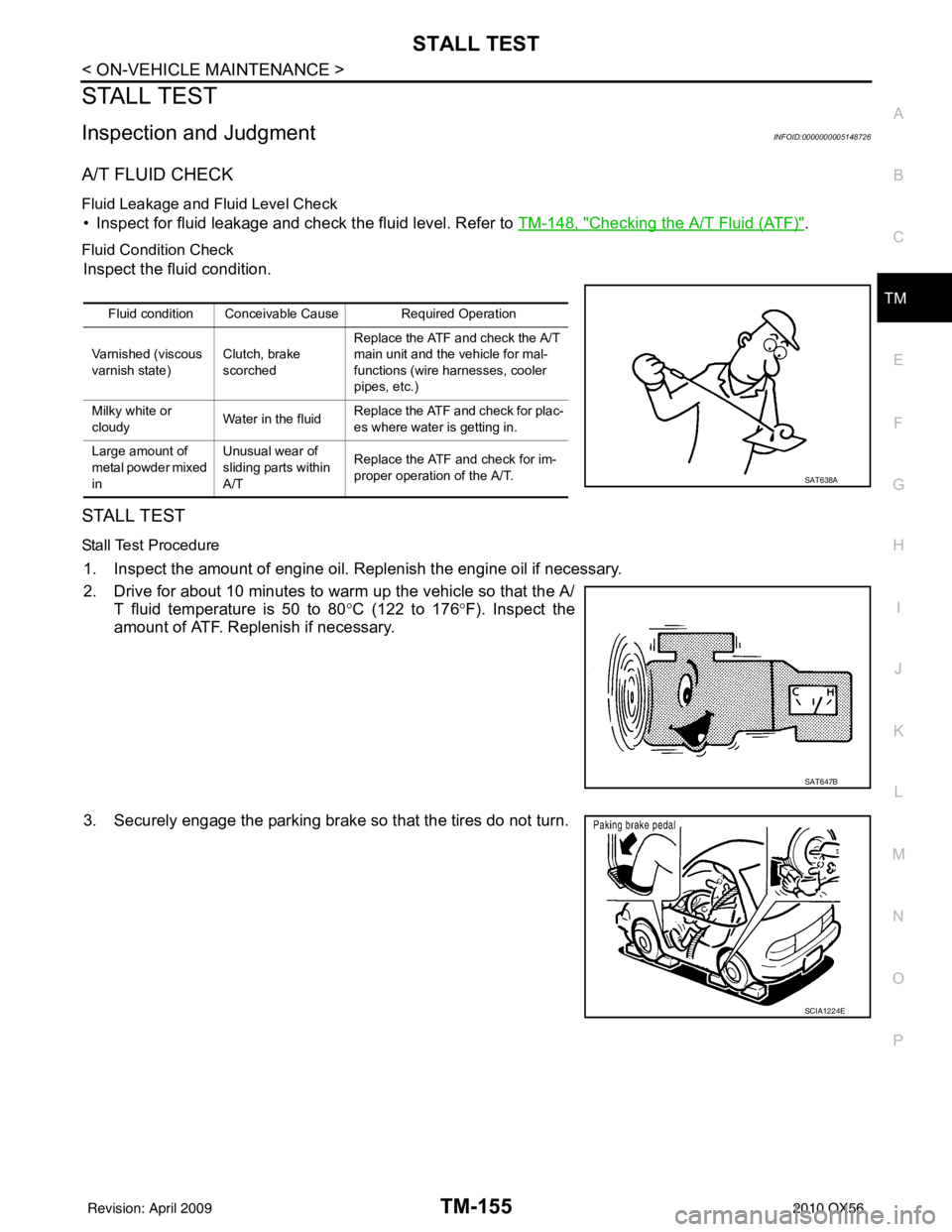
Inspect the fluid condition.
STALL TEST
Stall Test Procedure
1. Inspect the amount of engine oil. Replenish the engine oil if necessary.
2. Drive for about 10 minutes to warm up the vehicle so that the A/
T fluid temperature is 50 to 80 °C (122 to 176 °F). Inspect the
amount of ATF. Replenish if necessary.
3. Securely engage the parking brake so that the tires do not turn.
Fluid condition Conceivable Cause Required Operation
Varnished (viscous
varnish state) Clutch, brake
scorchedReplace the ATF and check the A/T
main unit and the vehicle for mal-
functions (wire harnesses, cooler
pipes, etc.)
Milky white or
cloudy Water in the fluidReplace the ATF and check for plac-
es where water is getting in.
Large amount of
metal powder mixed
in Unusual wear of
sliding parts within
A/T
Replace the ATF and check for im-
proper operation of the A/T.
SAT638A
SAT647B
SCIA1224E
Revision: April 20092010 QX56