2010 INFINITI QX56 air condition
[x] Cancel search: air conditionPage 2580 of 4210

SQUEAK AND RATTLE TROUBLE DIAGNOSESIP-7
< SYMPTOM DIAGNOSIS >
C
DE
F
G H
I
K L
M A
B
IP
N
O P
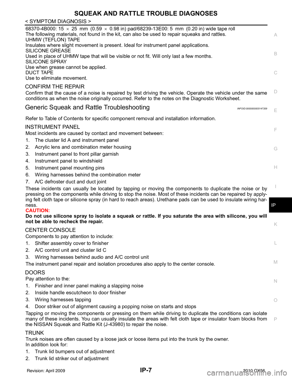
68370-4B000: 15 ×25 mm (0.59 ×0.98 in) pad/68239-13E00: 5 mm (0.20 in) wide tape roll
The following materials, not found in the kit, can also be used to repair squeaks and rattles.
UHMW (TEFLON) TAPE
Insulates where slight movement is present. Ideal for instrument panel applications.
SILICONE GREASE
Used in place of UHMW tape that will be visible or not fit. Will only last a few months.
SILICONE SPRAY
Use when grease cannot be applied.
DUCT TAPE
Use to eliminate movement.
CONFIRM THE REPAIR
Confirm that the cause of a noise is repaired by test driving the vehicle. Operate the vehicle under the same
conditions as when the noise originally occurred. Refer to the notes on the Diagnostic Worksheet.
Generic Squeak and Rattle TroubleshootingINFOID:0000000005147359
Refer to Table of Contents for specific component removal and installation information.
INSTRUMENT PANEL
Most incidents are caused by contact and movement between:
1. The cluster lid A and instrument panel
2. Acrylic lens and combination meter housing
3. Instrument panel to front pillar garnish
4. Instrument panel to windshield
5. Instrument panel mounting pins
6. Wiring harnesses behind the combination meter
7. A/C defroster duct and duct joint
These incidents can usually be located by tapping or moving the components to duplicate the noise or by
pressing on the components while driving to stop the noi se. Most of these incidents can be repaired by apply-
ing felt cloth tape or silicone spray (in hard to reach areas). Urethane pads can be used to insulate wiring har-
ness.
CAUTION:
Do not use silicone spray to isolate a squeak or ra ttle. If you saturate the area with silicone, you will
not be able to recheck the repair.
CENTER CONSOLE
Components to pay attention to include:
1. Shifter assembly cover to finisher
2. A/C control unit and cluster lid C
3. Wiring harnesses behind audio and A/C control unit
The instrument panel repair and isolation pr ocedures also apply to the center console.
DOORS
Pay attention to the:
1. Finisher and inner panel making a slapping noise
2. Inside handle escutcheon to door finisher
3. Wiring harnesses tapping
4. Door striker out of alignment causing a popping noise on starts and stops
Tapping or moving the components or pressing on them while driving to duplicate the conditions can isolate
many of these incidents. You can usually insulate the ar eas with felt cloth tape or insulator foam blocks from
the NISSAN Squeak and Rattle Kit (J-43980) to repair the noise.
TRUNK
Trunk noises are often caused by a loose jack or loose items put into the trunk by the owner.
In addition look for:
1. Trunk lid bumpers out of adjustment
2. Trunk lid striker out of adjustment
Revision: April 20092010 QX56
Page 2581 of 4210

IP-8
< SYMPTOM DIAGNOSIS >
SQUEAK AND RATTLE TROUBLE DIAGNOSES
3. The trunk lid torsion bars knocking together
4. A loose license plate or bracket
Most of these incidents can be repaired by adjusting, securing or insulating the item(s) or component(s) caus-
ing the noise.
SUNROOF/HEADLINING
Noises in the sunroof/headlining area c an often be traced to one of the following:
1. Sunroof lid, rail, linkage or seals making a rattle or light knocking noise
2. Sun visor shaft shaking in the holder
3. Front or rear windshield touching headliner and squeaking
Again, pressing on the components to stop the noise while duplicating the conditions can isolate most of these
incidents. Repairs usually consist of insulating with felt cloth tape.
OVERHEAD CONSOLE (FRONT AND REAR)
Overhead console noises are often caused by the c onsole panel clips not being engaged correctly. Most of
these incidents are repaired by pushing up on the c onsole at the clip locations until the clips engage.
In addition look for:
1. Loose harness or harness connectors.
2. Front console map/reading lamp lens loose.
3. Loose screws at console attachment points.
SEATS
When isolating seat noise it's important to note the pos ition the seat is in and the load placed on the seat when
the noise is present. These conditions should be duplicated when verifying and isolating the cause of the
noise.
Cause of seat noise include:
1. Headrest rods and holder
2. A squeak between the seat pad cushion and frame
3. The rear seatback lock and bracket
These noises can be isolated by moving or pressing on the suspected components while duplicating the con-
ditions under which the noise occurs. Most of thes e incidents can be repaired by repositioning the component
or applying urethane tape to the contact area.
UNDERHOOD
Some interior noise may be caused by components under the hood or on the engine wall. The noise is then
transmitted into the passenger compartment.
Causes of transmitted underhood noise include:
1. Any component mounted to the engine wall
2. Components that pass through the engine wall
3. Engine wall mounts and connectors
4. Loose radiator mounting pins
5. Hood bumpers out of adjustment
6. Hood striker out of adjustment
These noises can be difficult to isolate since they cannot be reached from the interior of the vehicle. The best
method is to secure, move or insulate one component at a time and test drive the \
vehicle. Also, engine RPM
or load can be changed to isolate the noise. Repairs can usually be made by moving, adjusting, securing, or
insulating the component causing the noise.
Revision: April 20092010 QX56
Page 2599 of 4210

LAN
LAN-1
ELECTRICAL & POWER CONTROL
C
DE
F
G H
I
J
K L
B
SECTION LAN
A
O P
N
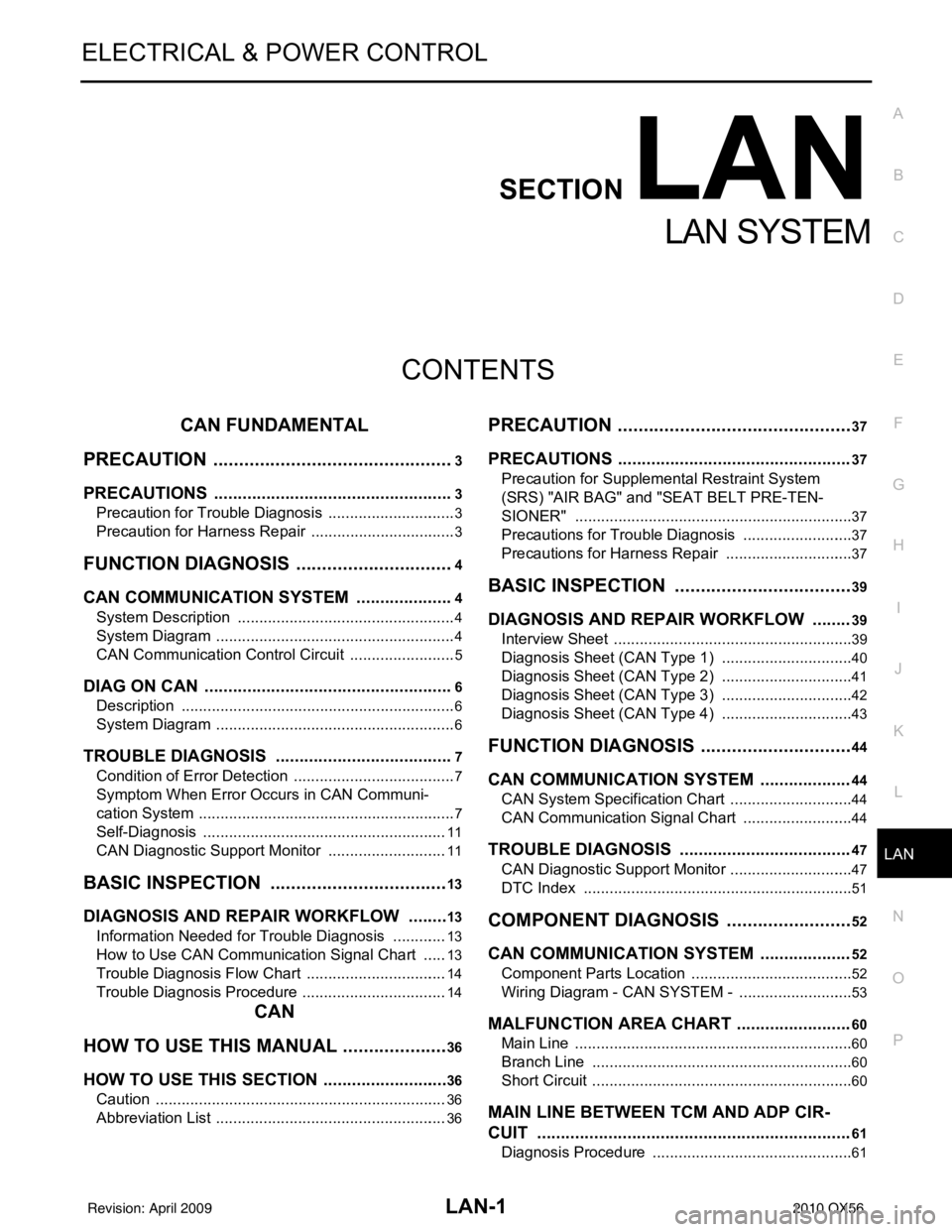
CONTENTS
LAN SYSTEM
CAN FUNDAMENTAL
PRECAUTION ....... ........................................
3
PRECAUTIONS .............................................. .....3
Precaution for Trouble Diagnosis ........................ ......3
Precaution for Harness Repair ..................................3
FUNCTION DIAGNOSIS .. .............................4
CAN COMMUNICATION SYSTEM ................ .....4
System Description ............................................. ......4
System Diagram ........................................................4
CAN Communication Control Circuit .........................5
DIAG ON CAN .....................................................6
Description .......................................................... ......6
System Diagram ........................................................6
TROUBLE DIAGNOSIS ......................................7
Condition of Error Detection ................................ ......7
Symptom When Error Occurs in CAN Communi-
cation System ...................................................... ......
7
Self-Diagnosis .........................................................11
CAN Diagnostic Support Monitor ............................11
BASIC INSPECTION ...................................13
DIAGNOSIS AND REPAIR WORKFLOW ..... ....13
Information Needed for Trouble Diagnosis ......... ....13
How to Use CAN Communication Signal Chart ......13
Trouble Diagnosis Flow Chart .................................14
Trouble Diagnosis Procedure ..................................14
CAN
HOW TO USE THIS MANU AL .....................
36
HOW TO USE THIS SECTION ....................... ....36
Caution ................................................................ ....36
Abbreviation List ......................................................36
PRECAUTION ..............................................37
PRECAUTIONS .................................................37
Precaution for Supplemental Restraint System
(SRS) "AIR BAG" and "SEAT BELT PRE-TEN-
SIONER" ............................................................. ....
37
Precautions for Trouble Diagnosis ..........................37
Precautions for Harness Repair ..............................37
BASIC INSPECTION ...................................39
DIAGNOSIS AND REPAIR WORKFLOW ........39
Interview Sheet .................................................... ....39
Diagnosis Sheet (CAN Type 1) ...............................40
Diagnosis Sheet (CAN Type 2) ...............................41
Diagnosis Sheet (CAN Type 3) ...............................42
Diagnosis Sheet (CAN Type 4) ...............................43
FUNCTION DIAGNOSIS ..............................44
CAN COMMUNICATION SYSTEM ...................44
CAN System Specification Chart ......................... ....44
CAN Communication Signal Chart ..........................44
TROUBLE DIAGNOSIS ....................................47
CAN Diagnostic Support Monitor .............................47
DTC Index ...............................................................51
COMPONENT DIAGNOSIS .........................52
CAN COMMUNICATION SYSTEM ...................52
Component Parts Location .................................. ....52
Wiring Diagram - CAN SYSTEM - ...........................53
MALFUNCTION AREA CHART ........................60
Main Line ............................................................. ....60
Branch Line .............................................................60
Short Circuit .............................................................60
MAIN LINE BETWEEN TCM AND ADP CIR-
CUIT ..................................................................
61
Diagnosis Procedure ...............................................61
Revision: April 20092010 QX56
Page 2611 of 4210
![INFINITI QX56 2010 Factory Service Manual LAN
DIAGNOSIS AND REPAIR WORKFLOWLAN-13
< BASIC INSPECTION > [CAN FUNDAMENTAL]
C
D
E
F
G H
I
J
K L
B A
O P
N
BASIC INSPECTION
DIAGNOSIS AND REPAIR WORKFLOW
Information Needed for Trouble DiagnosisINFO INFINITI QX56 2010 Factory Service Manual LAN
DIAGNOSIS AND REPAIR WORKFLOWLAN-13
< BASIC INSPECTION > [CAN FUNDAMENTAL]
C
D
E
F
G H
I
J
K L
B A
O P
N
BASIC INSPECTION
DIAGNOSIS AND REPAIR WORKFLOW
Information Needed for Trouble DiagnosisINFO](/manual-img/42/57032/w960_57032-2610.png)
LAN
DIAGNOSIS AND REPAIR WORKFLOWLAN-13
< BASIC INSPECTION > [CAN FUNDAMENTAL]
C
D
E
F
G H
I
J
K L
B A
O P
N
BASIC INSPECTION
DIAGNOSIS AND REPAIR WORKFLOW
Information Needed for Trouble DiagnosisINFOID:0000000005146448
CAN communication system performs trouble diagnosis with the following tools.
How to Use CAN Communication Signal ChartINFOID:0000000005146449
The CAN communication signal chart lists the signals needed for trouble diagnosis. It is useful for detecting
the root cause by finding a signal related to the sy
mptom, and by checking transmission and reception unit.
To o l U s a g e
Interview sheet For filling in vehicle information and interview with customer.
Data sheet For copying on-board diagnosis data.
Diagnosis sheet For detecting the root cause. (Diagnosis sheet includes system diagram for every CAN system type)
ECU list
(On the “CAN DIAG SUPPORT
MNTR”) For checking the condition of control units and the status of CAN communication.
SELF-DIAG RESULTS
(CONSULT-III)
CAN DIAG SUPPORT MNTR
(CONSULT-III)
CAN communication signal
chart For converting information received from a customer into CAN communication signal transmission
and reception. This information can be used to judge whether a circuit between control units is nor-
mal or abnormal.
Abbreviation list For checking abbreviations in CAN communication signal chart and diagnosis sheet.
SKIB8715E
Revision: April 20092010 QX56
Page 2612 of 4210
![INFINITI QX56 2010 Factory Service Manual LAN-14
< BASIC INSPECTION >[CAN FUNDAMENTAL]
DIAGNOSIS AND REPAIR WORKFLOW
Trouble Diagnosis Flow Chart
INFOID:0000000005146450
Trouble Diagnosis ProcedureINFOID:0000000005146451
INTERVIEW WITH CUSTOM INFINITI QX56 2010 Factory Service Manual LAN-14
< BASIC INSPECTION >[CAN FUNDAMENTAL]
DIAGNOSIS AND REPAIR WORKFLOW
Trouble Diagnosis Flow Chart
INFOID:0000000005146450
Trouble Diagnosis ProcedureINFOID:0000000005146451
INTERVIEW WITH CUSTOM](/manual-img/42/57032/w960_57032-2611.png)
LAN-14
< BASIC INSPECTION >[CAN FUNDAMENTAL]
DIAGNOSIS AND REPAIR WORKFLOW
Trouble Diagnosis Flow Chart
INFOID:0000000005146450
Trouble Diagnosis ProcedureINFOID:0000000005146451
INTERVIEW WITH CUSTOMER
Interview with the customer is important to detect the root cause of CAN communication system errors and to
understand vehicle condition and symptoms for proper trouble diagnosis.
Points in interview• What: Parts name, system name
• When: Date, Frequency
• Where: Road condition, Place
• In what condition: Driving condition/environment
PKID1210E
Revision: April 20092010 QX56
Page 2613 of 4210
![INFINITI QX56 2010 Factory Service Manual LAN
DIAGNOSIS AND REPAIR WORKFLOWLAN-15
< BASIC INSPECTION > [CAN FUNDAMENTAL]
C
D
E
F
G H
I
J
K L
B A
O P
N
• Result: Symptom
NOTE:
• Check normal units as well as error symptoms.
- Example: Circ INFINITI QX56 2010 Factory Service Manual LAN
DIAGNOSIS AND REPAIR WORKFLOWLAN-15
< BASIC INSPECTION > [CAN FUNDAMENTAL]
C
D
E
F
G H
I
J
K L
B A
O P
N
• Result: Symptom
NOTE:
• Check normal units as well as error symptoms.
- Example: Circ](/manual-img/42/57032/w960_57032-2612.png)
LAN
DIAGNOSIS AND REPAIR WORKFLOWLAN-15
< BASIC INSPECTION > [CAN FUNDAMENTAL]
C
D
E
F
G H
I
J
K L
B A
O P
N
• Result: Symptom
NOTE:
• Check normal units as well as error symptoms.
- Example: Circuit between ECM and the combination meter is judged normal if the customer indicates
tachometer functions normally.
• When a CAN communication system error is present, multiple control units may malfunction or go into fail-
safe mode.
• Indication of the combination meter is important to detect the root cause because it is the most obvious to
the customer, and it performs CAN communication with many units.
INSPECTION OF VEHICLE CONDITION
• Check whether or not “U1000” or “U1001” is indi cated on “SELF-DIAG RESULTS” by CONSULT-III.
NOTE:
Root cause cannot be detected using the procedure in this section if “U1000” or “U1001” is not indicated.
• Check whether the symptom is reproduced or not.
NOTE:
• Do not turn the ignition switch OFF or disconnect the battery cable while reproducing the error. The error may temporarily correct itself, making it difficult to determine the root cause.
• The procedures for present errors differ from the procedures for past errors. Refer to “DETECT THE ROOT CAUSE”.
CHECK OF CAN SYSTEM TYPE (HOW TO USE CAN SYSTEM TYPE SPECIFICATION CHART)
Determine CAN system type based on vehicle equipm ent. Then choose the correct diagnosis sheet.
NOTE:
There are two styles for CAN system type specificat ion charts. Depending on the number of available system
types, either style A or style B may be used.
CAN System Type Specification Chart (Style A)
NOTE:
SKIB8717E
Revision: April 20092010 QX56
Page 2615 of 4210
![INFINITI QX56 2010 Factory Service Manual LAN
DIAGNOSIS AND REPAIR WORKFLOWLAN-17
< BASIC INSPECTION > [CAN FUNDAMENTAL]
C
D
E
F
G H
I
J
K L
B A
O P
N
CAN system type is easily checked wi
th the vehicle equipment identification information sh INFINITI QX56 2010 Factory Service Manual LAN
DIAGNOSIS AND REPAIR WORKFLOWLAN-17
< BASIC INSPECTION > [CAN FUNDAMENTAL]
C
D
E
F
G H
I
J
K L
B A
O P
N
CAN system type is easily checked wi
th the vehicle equipment identification information sh](/manual-img/42/57032/w960_57032-2614.png)
LAN
DIAGNOSIS AND REPAIR WORKFLOWLAN-17
< BASIC INSPECTION > [CAN FUNDAMENTAL]
C
D
E
F
G H
I
J
K L
B A
O P
N
CAN system type is easily checked wi
th the vehicle equipment identification information shown in the chart.
CREATE INTERVIEW SHEET
Fill out the symptom described by the customer, vehicle condition, and CAN system type on the interview
sheet.
SKIB8889E
Revision: April 20092010 QX56
Page 2710 of 4210

MA-6
< ON-VEHICLE MAINTENANCE >
GENERAL MAINTENANCE
ON-VEHICLE MAINTENANCE
GENERAL MAINTENANCE
General MaintenanceINFOID:0000000005145933
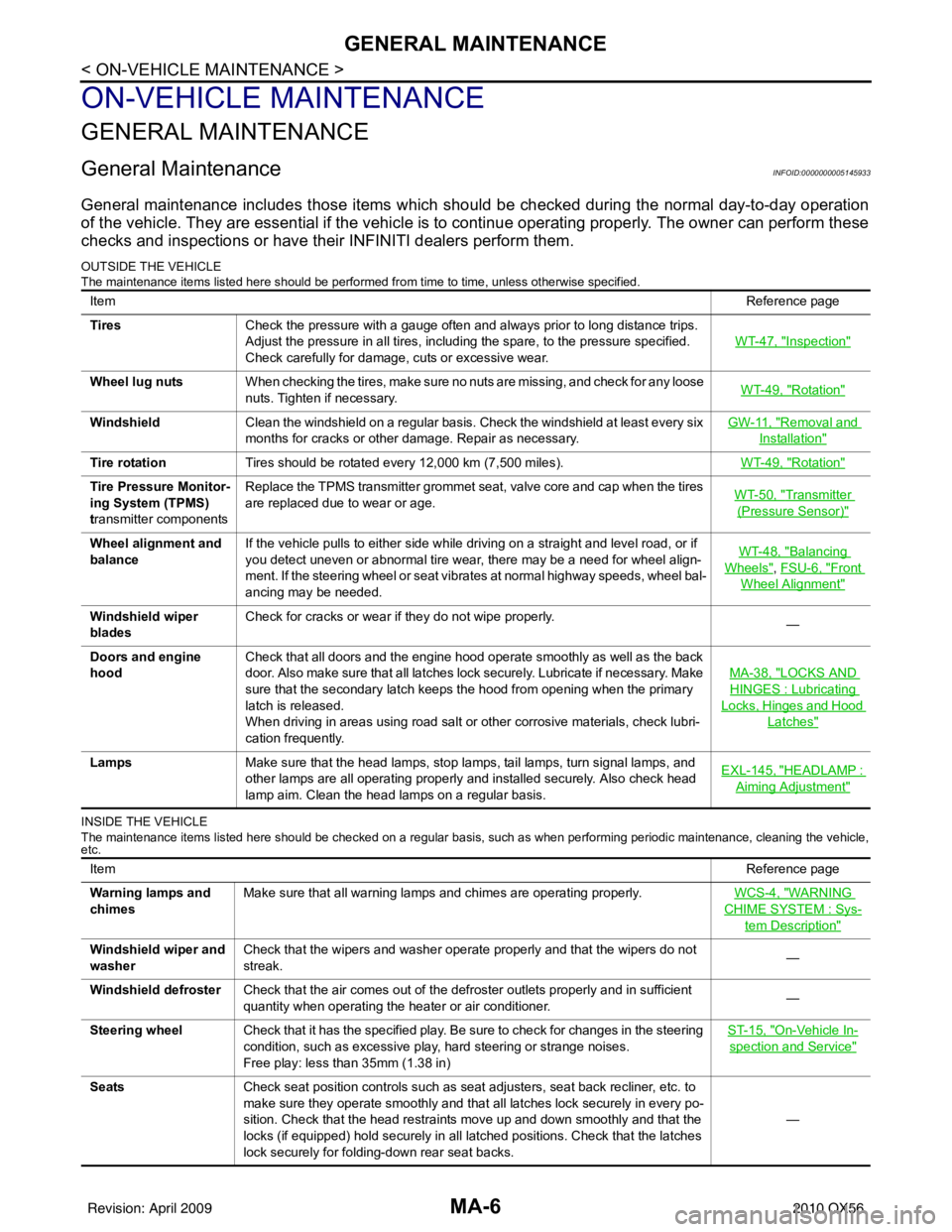
General maintenance includes those items which should be checked during the normal day-to-day operation
of the vehicle. They are essential if the vehicle is to continue operating properly. The owner can perform these
checks and inspections or have thei r INFINITI dealers perform them.
OUTSIDE THE VEHICLE
The maintenance items listed here should be performed fr om time to time, unless otherwise specified.
INSIDE THE VEHICLE
The maintenance items listed here should be checked on a regular basis, such as when performing periodic maintenance, cleaning the vehicle,
etc.
Item Reference page
Tires Check the pressure with a gauge often and always prior to long distance trips.
Adjust the pressure in all tires, including the spare, to the pressure specified.
Check carefully for damage, cuts or excessive wear. WT-47, "
Inspection"
Wheel lug nuts
When checking the tires, make sure no nuts are missing, and check for any loose
nuts. Tighten if necessary. WT-49, "Rotation"
Windshield
Clean the windshield on a regular basis. Check the windshield at least every six
months for cracks or other damage. Repair as necessary. GW-11, "Removal and
Installation"
Tire rotation
Tires should be rotated every 12,000 km (7,500 miles). WT-49, "Rotation"
Tire Pressure Monitor-
ing System (TPMS)
transmitter componentsReplace the TPMS transmitter grommet seat, valve core and cap when the tires
are replaced due to wear or age.
WT-50, "Transmitter
(Pressure Sensor)"
Wheel alignment and
balanceIf the vehicle pulls to either side while driving on a straight and level road, or if
you detect uneven or abnormal tire wear, there may be a need for wheel align-
ment. If the steering wheel or seat vibrates at normal highway speeds, wheel bal-
ancing may be needed. WT-48, "Balancing
Wheels", FSU-6, "Front
Wheel Alignment"
Windshield wiper
blades
Check for cracks or wear if they do not wipe properly.
—
Doors and engine
hood Check that all doors and the engine hood operate smoothly as well as the back
door. Also make sure that all latches lock securely. Lubricate if necessary. Make
sure that the secondary latch keeps the hood from opening when the primary
latch is released.
When driving in areas using road salt or other corrosive materials, check lubri-
cation frequently. MA-38, "
LOCKS AND
HINGES : Lubricating
Locks, Hinges and Hood
Latches"
Lamps
Make sure that the head lamps, stop lamps, tail lamps, turn signal lamps, and
other lamps are all operating properly and installed securely. Also check head
lamp aim. Clean the head lamps on a regular basis. EXL-145, "HEADLAMP :
Aiming Adjustment"
Item
Reference page
Warning lamps and
chimes Make sure that all warning lamps and chimes are operating properly.
WCS-4, "
WARNING
CHIME SYSTEM : Sys-
tem Description"
Windshield wiper and
washerCheck that the wipers and washer operate properly and that the wipers do not
streak.
—
Windshield defroster Check that the air comes out of the defroster outlets properly and in sufficient
quantity when operating the heater or air conditioner. —
Steering wheel Check that it has the specified play. Be sure to check for changes in the steering
condition, such as excessive play, hard steering or strange noises.
Free play: less than 35mm (1.38 in) ST-15, "
On-Vehicle In-
spection and Service"
Seats
Check seat position controls such as seat adjusters, seat back recliner, etc. to
make sure they operate smoothly and that all latches lock securely in every po-
sition. Check that the head restraints move up and down smoothly and that the
locks (if equipped) hold securely in all latched positions. Check that the latches
lock securely for folding-down rear seat backs. —
Revision: April 20092010 QX56