2010 INFINITI QX56 air condition
[x] Cancel search: air conditionPage 2791 of 4210
MWI
POWER SUPPLY AND GROUND CIRCUITMWI-29
< COMPONENT DIAGNOSIS >
C
DE
F
G H
I
J
K L
M B A
O P
YES >> Inspection End.
NO >> Check ground harness.
BCM (BODY CONTROL MODULE)
BCM (BODY CONTROL MODULE) : Diagnosis ProcedureINFOID:0000000005380655
Regarding Wiring Diagram information, refer to MWI-70, "Wiring Diagram".
1. CHECK FUSES AND FUSIBLE LINK
Check that the following fuses and fusible link are not blown.
Is the fuse blown?
YES >> Replace the blown fuse or fusible link after repairing the affected circuit.
NO >> GO TO 2
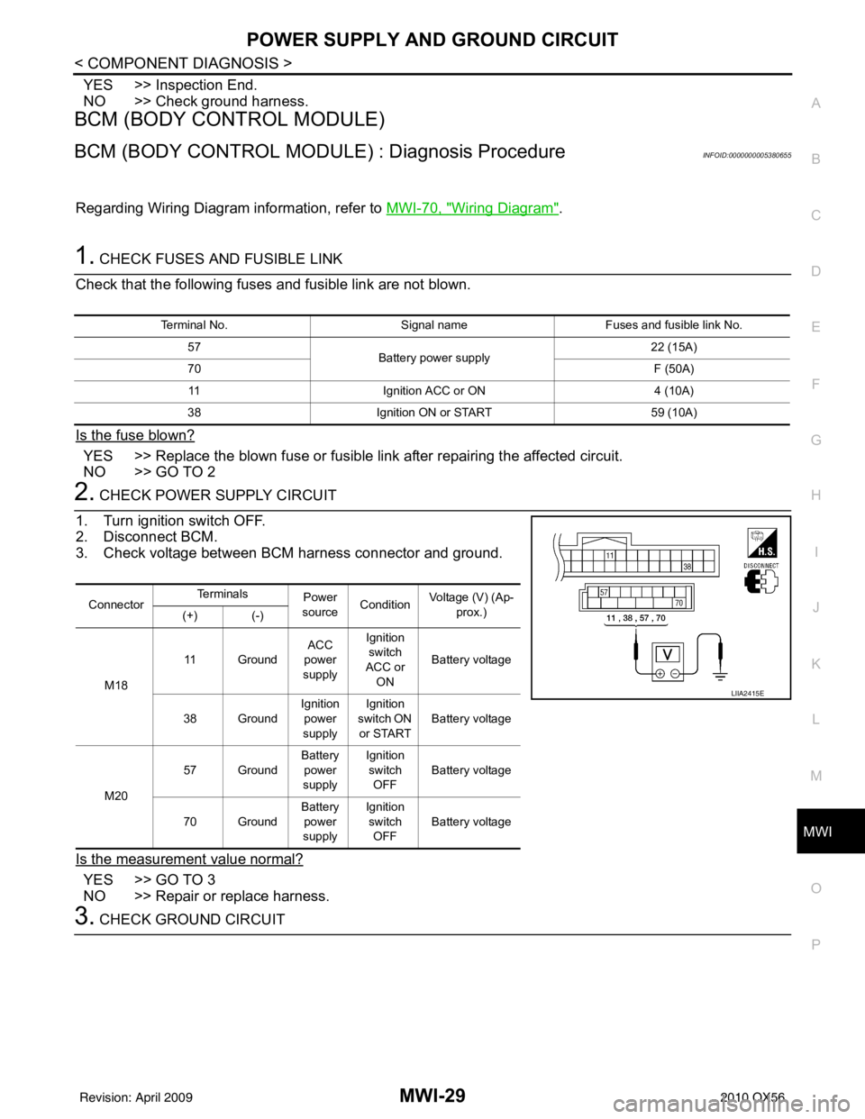
2. CHECK POWER SUPPLY CIRCUIT
1. Turn ignition switch OFF.
2. Disconnect BCM.
3. Check voltage between BCM harness connector and ground.
Is the measurement value normal?
YES >> GO TO 3
NO >> Repair or replace harness.
3. CHECK GROUND CIRCUIT
Terminal No. Signal nameFuses and fusible link No.
57 Battery power supply 22 (15A)
70 F (50A)
11 Ignition ACC or ON 4 (10A)
38 Ignition ON or START 59 (10A)
ConnectorTe r m i n a l s
Power
source Condition Voltage (V) (Ap-
prox.)
(+) (-)
M18 11 Ground
ACC
power
supply Ignition
switch
ACC or ON Battery voltage
38 Ground Ignition
power
supply Ignition
switch ON
or START Battery voltage
M20 57 Ground
Battery
power
supply Ignition
switch OFF Battery voltage
70 Ground Battery
power
supply Ignition
switch OFF Battery voltage
LIIA2415E
Revision: April 20092010 QX56
Page 2795 of 4210
MWI
FUEL LEVEL SENSOR SIGNAL CIRCUITMWI-33
< COMPONENT DIAGNOSIS >
C
DE
F
G H
I
J
K L
M B A
O P
Is the inspection result normal?
YES >> GO TO 3
NO >> Repair harness or connector.
3.CHECK FUEL LEVEL SENS OR UNIT GROUND CIRCUIT
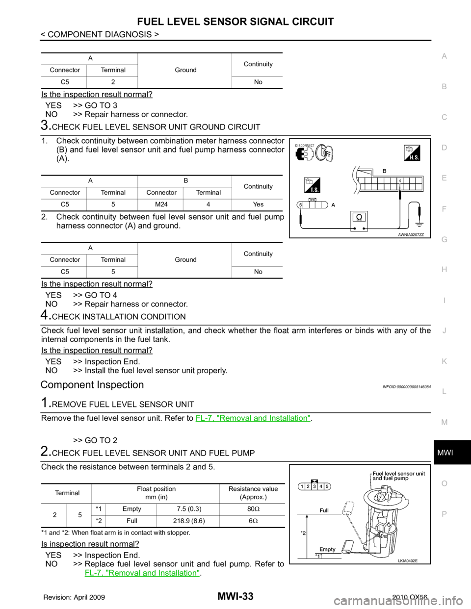
1. Check continuity between combination meter harness connector (B) and fuel level sensor unit and fuel pump harness connector
(A).
2. Check continuity between fuel level sensor unit and fuel pump harness connector (A) and ground.
Is the inspection result normal?
YES >> GO TO 4
NO >> Repair harness or connector.
4.CHECK INSTALLATION CONDITION
Check fuel level sensor unit installation, and check whet her the float arm interferes or binds with any of the
internal components in the fuel tank.
Is the inspection result normal?
YES >> Inspection End.
NO >> Install the fuel level sensor unit properly.
Component InspectionINFOID:0000000005146084
1.REMOVE FUEL LEVEL SENSOR UNIT
Remove the fuel level sensor unit. Refer to FL-7, "
Removal and Installation".
>> GO TO 2
2.CHECK FUEL LEVEL SENSOR UNIT AND FUEL PUMP
Check the resistance between terminals 2 and 5.
*1 and *2: When float arm is in contact with stopper.
Is inspection result normal?
YES >> Inspection End.
NO >> Replace fuel level sensor unit and fuel pump. Refer to FL-7, "
Removal and Installation".
A
GroundContinuity
Connector Terminal
C5 2 No
AB
Continuity
Connector Terminal Connector Terminal
C5 5 M24 4 Yes
A GroundContinuity
Connector Terminal
C5 5 No
AWNIA0207ZZ
Te r m i n a lFloat position
mm (in) Resistance value
(Approx.)
25 *1 Empty 7.5 (0.3) 80
Ω
*2 Full 218.9 (8.6)6Ω
LKIA0402E
Revision: April 20092010 QX56
Page 2796 of 4210
MWI-34
< COMPONENT DIAGNOSIS >
OIL PRESSURE SWITCH SIGNAL CIRCUIT
OIL PRESSURE SWITCH SIGNAL CIRCUIT
DescriptionINFOID:0000000005146085
Detects the engine oil pressure and transmits the oil pressure switch signal to the IPDM E/R.
Component Function CheckINFOID:0000000005146086
1.COMBINATION METER INPUT SIGNAL
1. Select “METER/M&A” on CONSULT-III.
2. Monitor “OIL W/L” of “DATA MONITOR” while operating ignition switch.
>> Inspection End.
Diagnosis ProcedureINFOID:0000000005146087
Regarding Wiring Diagram information, refer to MWI-41, "Wiring Diagram".
1.CHECK OIL PRESSURE SWITCH CIRCUIT
1. Turn ignition switch OFF.
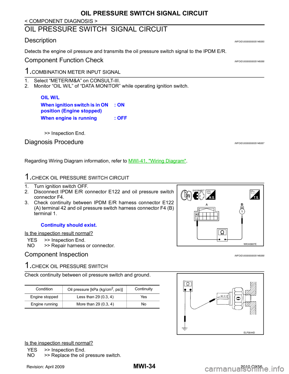
2. Disconnect IPDM E/R connector E122 and oil pressure switch
connector F4.
3. Check continuity between IPDM E/R harness connector E122
(A) terminal 42 and oil pressure switch harness connector F4 (B)
terminal 1.
Is the inspection result normal?
YES >> Inspection End.
NO >> Repair harness or connector.
Component InspectionINFOID:0000000005146088
1.CHECK OIL PRESSURE SWITCH
Check continuity between oil pressure switch and ground.
Is the inspection result normal?
YES >> Inspection End.
NO >> Replace the oil pressure switch. OIL W/L
When ignition switch is in ON
position (Engine stopped)
: ON
When engine is running : OFF
Continuity should exist.
WKIA5607E
Condition Oil pressure [kPa (kg/cm2, psi)]Continuity
Engine stopped Less than 29 (0.3, 4) Yes
Engine running More than 29 (0.3, 4) No
ELF0044D
Revision: April 20092010 QX56
Page 2797 of 4210
MWI
PARKING BRAKE SWITCH SIGNAL CIRCUITMWI-35
< COMPONENT DIAGNOSIS >
C
DE
F
G H
I
J
K L
M B A
O P
PARKING BRAKE SWITCH SIGNAL CIRCUIT
DescriptionINFOID:0000000005146089
Transmits the parking brake switch signal to the combination meter.
Component Function CheckINFOID:0000000005146090
1.COMBINATION METER INPUT SIGNAL
1. Start engine.
2. Monitor “BRAKE” warning lamp while applying and releasing the parking brake.
>> Inspection End.
Diagnosis ProcedureINFOID:0000000005146091
Regarding Wiring Diagram information, refer to MWI-41, "Wiring Diagram".
1.CHECK PARKING BRAKE SWITCH CIRCUIT
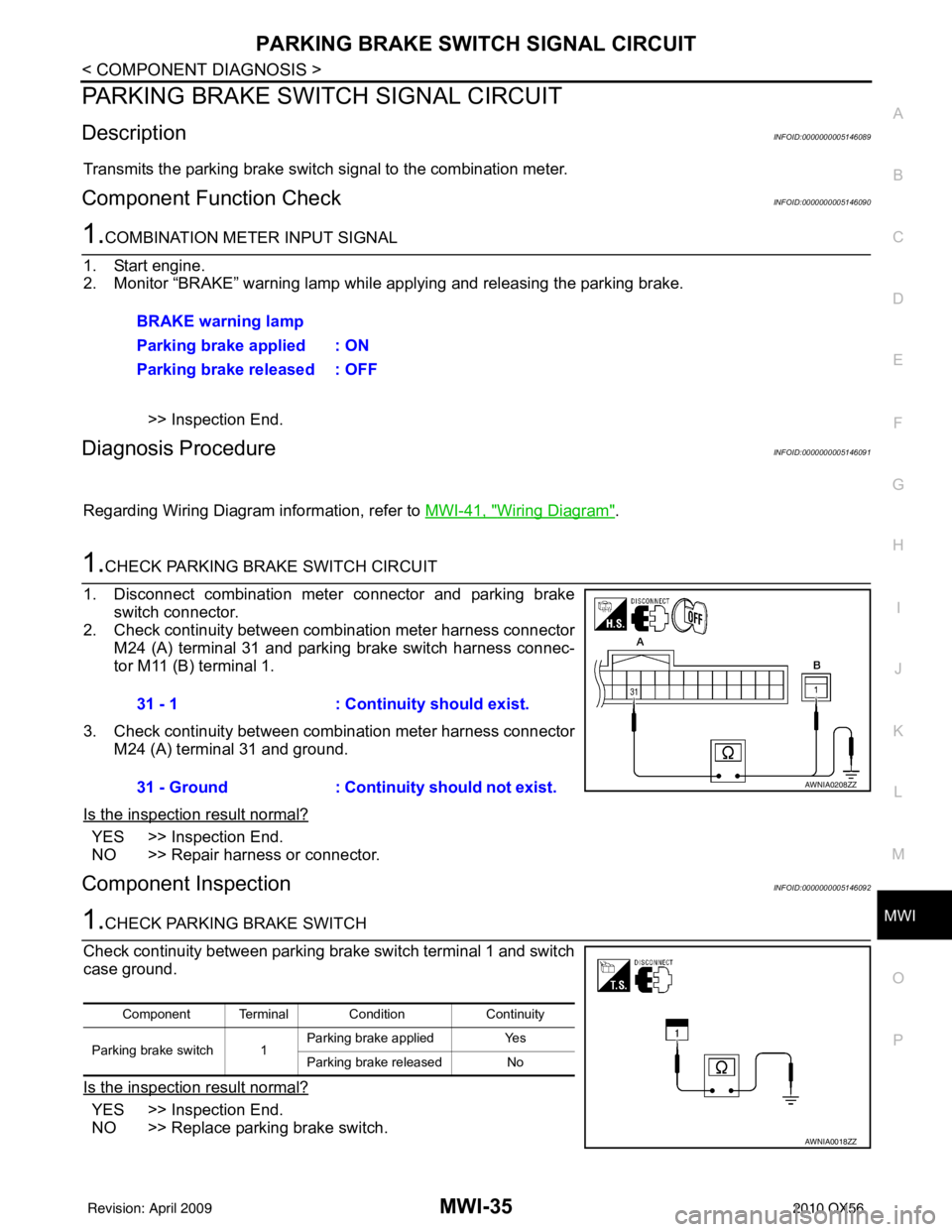
1. Disconnect combination meter connector and parking brake switch connector.
2. Check continuity between combination meter harness connector M24 (A) terminal 31 and parking brake switch harness connec-
tor M11 (B) terminal 1.
3. Check continuity between combination meter harness connector M24 (A) terminal 31 and ground.
Is the inspection result normal?
YES >> Inspection End.
NO >> Repair harness or connector.
Component InspectionINFOID:0000000005146092
1.CHECK PARKING BRAKE SWITCH
Check continuity between parking brake switch terminal 1 and switch
case ground.
Is the inspection result normal?
YES >> Inspection End.
NO >> Replace parking brake switch. BRAKE warning lamp
Parking brake applied : ON
Parking brake released : OFF
31 - 1
: Continuity should exist.
31 - Ground : Continuity should not exist.
AWNIA0208ZZ
Component Terminal Condition Continuity
Parking brake switch 1 Parking brake applied
Yes
Parking brake released No
AWNIA0018ZZ
Revision: April 20092010 QX56
Page 2801 of 4210
MWI
COMBINATION METERMWI-39
< ECU DIAGNOSIS >
C
DE
F
G H
I
J
K L
M B A
O P
ECU DIAGNOSIS
COMBINATION METER
Reference ValueINFOID:0000000005146098
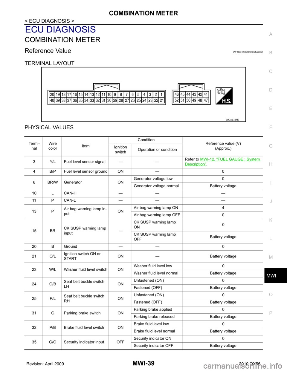
TERMINAL LAYOUT
PHYSICAL VALUES
WKIA5724E
Te r m i - nal Wire
color Item Condition
Reference value (V)
(Approx.)
Ignition
switch Operation or condition
3 Y/L Fuel level sensor signal — —Refer to
MWI-12, "
FUEL GAUGE : System
Description".
4 B/P Fuel level sensor ground ON —0
6 BR/W Generator ONGenerator voltage low
0
Generator voltage normal Battery voltage
10 L CAN-H —— —
11 P C A N - L —— —
13 P Air bag warning lamp in-
put ONAir bag warning lamp ON
4
Air bag warning lamp OFF 0
15 BR CK SUSP warning lamp
input —CK SUSP warning lamp
ON
0
CK SUSP warning lamp
OFF Battery voltage
20 B Ground —— 0
21 O/L Ignition switch ON or
START ON
— Battery voltage
23 W/L Washer fluid level switch ON Washer fluid level low
0
Washer fluid level normal Battery voltage
24 O/B Seat belt buckle switch
LH ONUnfastened (ON)
0
Fastened (OFF) Battery voltage
25 P/L Seat belt buckle switch
RH ONUnfastened (ON)
0
Fastened (OFF) Battery voltage
31 G Parking brake switch ON Parking brake applied
0
Parking brake released Battery voltage
32 P/B Brake fluid level switch ON Brake fluid level low
0
Brake fluid level normal Battery voltage
35 G/O Security indicator input OFF Security indicator ON
0
Security indicator OFF Battery voltage
Revision: April 20092010 QX56
Page 2823 of 4210

MWI
BCM (BODY CONTROL MODULE)MWI-61
< ECU DIAGNOSIS >
C
DE
F
G H
I
J
K L
M B A
O P
BCM (BODY CONTROL MODULE)
Reference ValueINFOID:0000000005380657
VALUES ON THE DIAGNOSIS TOOL
Monitor Item Condition Value/Status
AIR COND SW A/C switch OFF
OFF
A/C switch ON ON
AUT LIGHT SYS Outside of the room is dark
OFF
Outside of the room is bright ON
AUTO LIGHT SW Lighting switch OFF
OFF
Lighting switch AUTO ON
BACK DOOR SW Back door closed
OFF
Back door opened ON
CARGO LAMP SW Cargo lamp switch OFF
OFF
Cargo lamp switch ON ON
CDL LOCK SW Door lock/unlock switch does not operate
OFF
Press door lock/unlock switch to the LOCK side ON
CDL UNLOCK SW Door lock/unlock switch does not operate
OFF
Press door lock/unlock switch to the UNLOCK side ON
DOOR SW-AS Front door RH closed
OFF
Front door RH opened ON
DOOR SW-DR Front door LH closed
OFF
Front door LH opened ON
DOOR SW-RL Rear door LH closed
OFF
Rear door LH opened ON
DOOR SW-RR Rear door RH closed
OFF
Rear door RH opened ON
ENGINE RUN Engine stopped
OFF
Engine running ON
FR FOG SW Front fog lamp switch OFF
OFF
Front fog lamp switch ON ON
FR WASHER SW Front washer switch OFF
OFF
Front washer switch ON ON
FR WIPER LOW Front wiper switch OFF
OFF
Front wiper switch LO ON
FR WIPER HI Front wiper switch OFF
OFF
Front wiper switch HI ON
FR WIPER INT Front wiper switch OFF
OFF
Front wiper switch INT ON
FR WIPER STOP Any position other than front wiper stop position
OFF
Front wiper stop position ON
HAZARD SW When hazard switch is not pressed
OFF
When hazard switch is pressed ON
Revision: April 20092010 QX56
Page 2839 of 4210

MWI
IPDM E/R (INTELLIGENT POWER DISTRIBUTION MODULE ENGINE ROOM)
MWI-77
< ECU DIAGNOSIS >
C
D E
F
G H
I
J
K L
M B A
O P
IPDM E/R (INTELLIGENT POWER DISTRIBUTION MODULE ENGINE
ROOM)
Reference ValueINFOID:0000000005380664
VALUES ON THE DIAGNOSIS TOOL
Monitor Item ConditionValue/Status
MOTOR FAN REQ Engine idle speed Changes depending on engine
coolant temperature, air conditioner
operation status, vehicle speed,
etc.0 - 100 %
A/C COMP REQ A/C switch OFF
OFF
A/C switch ON ON
TA I L & C L R R E Q Lighting switch OFF
OFF
Lighting switch 1ST, 2ND, HI or AUTO (Light is illuminated) ON
HL LO REQ Lighting switch OFF
OFF
Lighting switch 2ND HI or AUTO (Light is illuminated) ON
HL HI REQ Lighting switch OFF
OFF
Lighting switch HI ON
FR FOG REQ Lighting switch 2ND or AUTO (Light
is illuminated) Front fog lamp switch OFF OFF
• Front fog lamp switch ON
• Daytime light activated (Canada
only) ON
FR WIP REQ Ignition switch ON Front wiper switch OFF
STOP
Front wiper switch INT 1LOW
Front wiper switch LO LOW
Front wiper switch HI HI
WIP AUTO STOP Ignition switch ON Front wiper stop position
STOP P
Any position other than front wiper
stop position ACT P
WIP PROT Ignition switch ON Front wiper operates normally OFF
Front wiper stops at fail-safe opera-
tion
BLOCK
ST RLY REQ Ignition switch OFF or ACC
OFF
Ignition switch START ON
IGN RLY Ignition switch OFF or ACC
OFF
Ignition switch ON ON
RR DEF REQ Rear defogger switch OFF
OFF
Rear defogger switch ON ON
OIL P SW Ignition switch OFF, ACC or engine running
OPEN
Ignition switch ON CLOSE
DTRL REQ Daytime light system requested OFF with CONSULT-III.
OFF
Daytime light system reques ted ON with CONSULT-III. ON
HOOD SW Hood closed.
OFF
Hood open. ON
Revision: April 20092010 QX56
Page 2873 of 4210
PB-10
< ON-VEHICLE REPAIR >
PARKING BRAKE SHOE
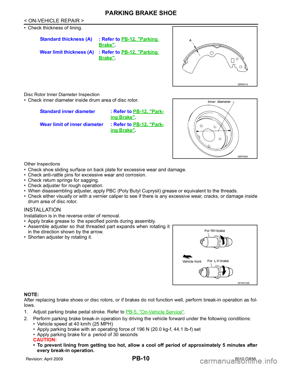
• Check thickness of lining.
Disc Rotor Inner Diameter Inspection
• Check inner diameter insi de drum area of disc rotor.
Other Inspections
• Check shoe sliding surface on back plate for excessive wear and damage.
• Check anti-rattle pins for excessive wear and corrosion.
• Check return springs for sagging.
• Check adjuster for rough operation.
• When disassembling adjuster, apply PBC (Poly Butyl Cuprysil) grease or equivalent to the threads.
• Check either visually or with a vernier caliper to see if there is any excessive wear, cracks, or damage inside
drum area of disc rotor.
INSTALLATION
Installation is in the reverse order of removal.
• Apply brake grease to the specified points during assembly.
• Assemble adjuster so that threaded part expands when rotating it
in the direction shown by the arrow.
• Shorten adjuster by rotating it.
NOTE:
After replacing brake shoes or disc rotors, or if brakes do not function well, perform break-in operation as fol-
lows.
1. Adjust parking brake pedal stroke. Refer to PB-5, "
On-Vehicle Service".
2. Perform parking brake break-in operation by driving the vehicle forward under the following conditions: • Vehicle speed at 40 km/h (25 MPH)
• Apply parking brake with an operating forc e of 196 N (20.0 kg-f, 44.1 lb-f) set
• Apply parking brake for a period of 30 seconds
CAUTION:
• To prevent lining from getting too hot, allow a cool off period of approximately 5 minutes after every break-in operation.Standard thickness (A) : Refer to
PB-12, "
Parking
Brake".
Wear limit thickness (A) : Refer to PB-12, "
Parking
Brake".
SBR021A
Standard inner diameter : Refer to PB-12, "Park-
ing Brake".
Wear limit of inner diameter : Refer to PB-12, "
Park-
ing Brake".
SBR768A
SFIA0153E
Revision: April 20092010 QX56