2010 INFINITI QX56 diagram
[x] Cancel search: diagramPage 2763 of 4210
MWI
MWI-1
DRIVER INFORMATION & MULTIMEDIA
C
DE
F
G H
I
J
K L
M B
SECTION MWI
A
O P
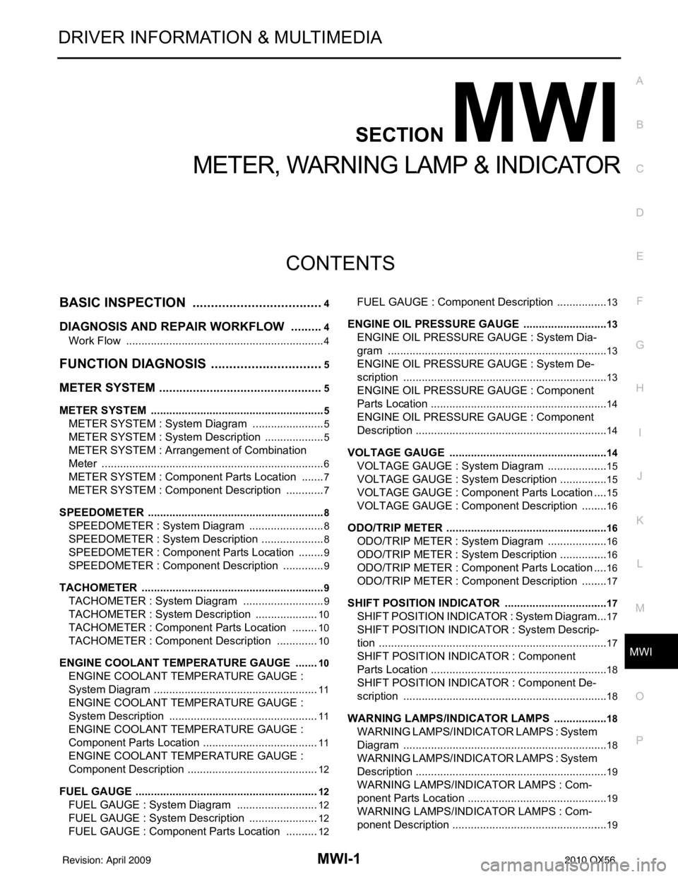
CONTENTS
METER, WARNING LAMP & INDICATOR
BASIC INSPECTION ....... .............................4
DIAGNOSIS AND REPAIR WORKFLOW ..... .....4
Work Flow ........................................................... ......4
FUNCTION DIAGNOSIS ...............................5
METER SYSTEM ............................................ .....5
METER SYSTEM .........................................................5
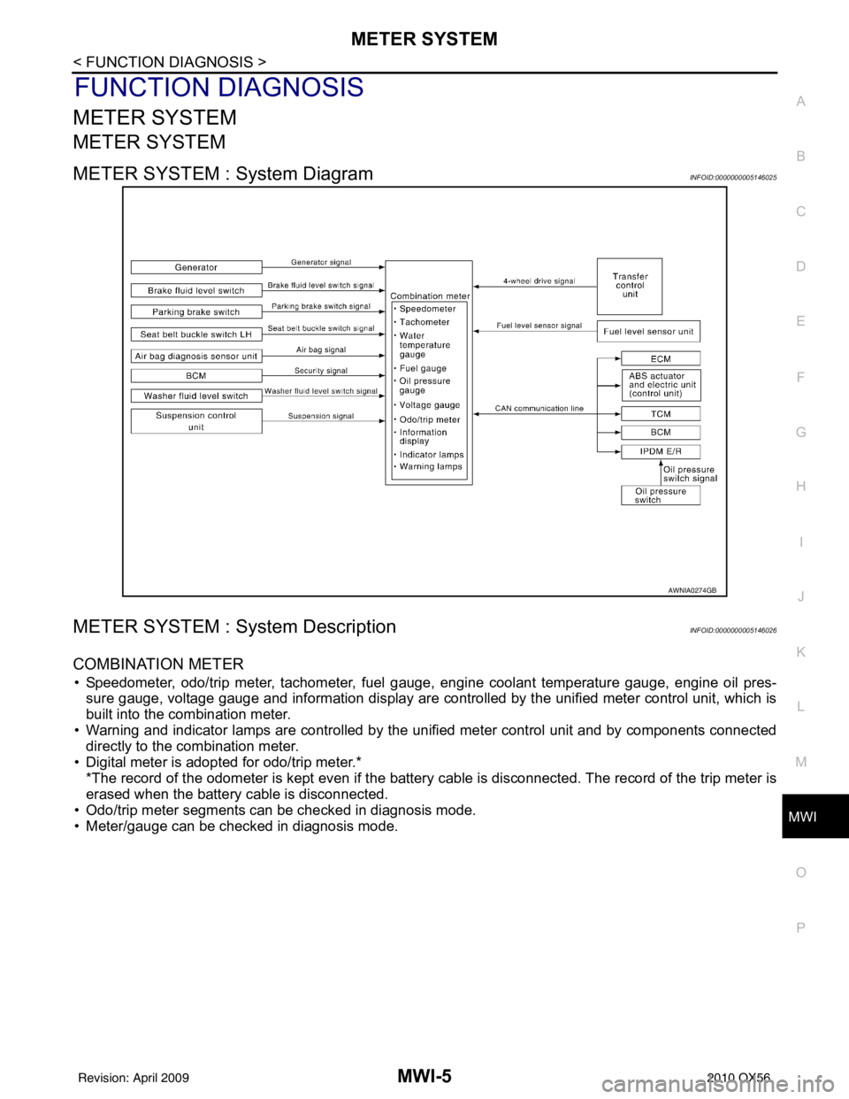
METER SYSTEM : System Diagram ........................5
METER SYSTEM : System Description ....................5
METER SYSTEM : Arrangem ent of Combination
Meter ................................................................... ......
6
METER SYSTEM : Component Parts Location ........7
METER SYSTEM : Component Description ....... ......7
SPEEDOMETER ..........................................................8
SPEEDOMETER : System Diagram ................... ......8
SPEEDOMETER : System Description .....................8
SPEEDOMETER : Component Parts Location .........9
SPEEDOMETER : Component Description ........ ......9
TACHOMETER ...................................................... ......9
TACHOMETER : System Diagram ...........................9
TACHOMETER : System De scription .....................10
TACHOMETER : Component Parts Location ..... ....10
TACHOMETER : Component Description ..............10
ENGINE COOLANT TEMPERATURE GAUGE .... ....10
ENGINE COOLANT TEMPERATURE GAUGE :
System Diagram ......................................................
11
ENGINE COOLANT TEMPERATURE GAUGE :
System Description .................................................
11
ENGINE COOLANT TEMPERATURE GAUGE :
Component Parts Location ......................................
11
ENGINE COOLANT TEMPERATURE GAUGE :
Component Description ...........................................
12
FUEL GAUGE ........................................................ ....12
FUEL GAUGE : System Diagram ...........................12
FUEL GAUGE : System Description .......................12
FUEL GAUGE : Component Parts Location ...........12
FUEL GAUGE : Component Description ............. ....13
ENGINE OIL PRESSURE GAUGE ............................13
ENGINE OIL PRESSURE GAUGE : System Dia-
gram .................................................................... ....
13
ENGINE OIL PRESSURE GAUGE : System De-
scription ...................................................................
13
ENGINE OIL PRESSURE GAUGE : Component
Parts Location ..........................................................
14
ENGINE OIL PRESSURE GAUGE : Component
Description ...............................................................
14
VOLTAGE GAUGE ................................................ ....14
VOLTAGE GAUGE : System Diagram ....................15
VOLTAGE GAUGE : System Description ................15
VOLTAGE GAUGE : Component Parts Location ....15
VOLTAGE GAUGE : Component Description .........16
ODO/TRIP METER ................................................. ....16
ODO/TRIP METER : System Diagram ....................16
ODO/TRIP METER : System Description ................16
ODO/TRIP METER : Component Parts Location ....16
ODO/TRIP METER : Component Description .........17
SHIFT POSITION INDICATOR .............................. ....17
SHIFT POSITION INDICATOR : System Diagram ....17
SHIFT POSITION INDICATOR : System Descrip-
tion ...........................................................................
17
SHIFT POSITION INDICATOR : Component
Parts Location ..........................................................
18
SHIFT POSITION INDICATOR : Component De-
scription ............................................................... ....
18
WARNING LAMPS/INDICATOR LAMPS .............. ....18
WARNING LAMPS/INDICATOR LAMPS : System
Diagram ............................................................... ....
18
WARNING LAMPS/INDICATOR LAMPS : System
Description ........................................................... ....
19
WARNING LAMPS/INDICATOR LAMPS : Com-
ponent Parts Location ..............................................
19
WARNING LAMPS/INDICATOR LAMPS : Com-
ponent Description ...................................................
19
Revision: April 20092010 QX56
Page 2764 of 4210

MWI-2
INFORMATION DISPLAY .........................................19
INFORMATION DISPLAY : System Diagram .........20
INFORMATION DISPLAY : System Description ....20
INFORMATION DISPLAY : Component Parts Lo-
cation ................................................................... ...
21
INFORMATION DISPLAY : Component Descrip-
tion ....................................................................... ...
21
DIAGNOSIS SYSTEM (METER) .......................22
Diagnosis Description .......................................... ...22
CONSULT-III Function (METER/M&A) ................ ...23
COMPONENT DIAGNOSIS ........................26
DTC U1000 CAN COMMUNICATION ............ ...26
DTC Logic ............................................................ ...26
Diagnosis Procedure .............................................26
DTC B2205 VEHICLE SPEED CIRCUIT ...........27
Description ........................................................... ...27
DTC Logic ...............................................................27
Diagnosis Procedure .............................................27
POWER SUPPLY AND GROUND CIRCUIT .....28
COMBINATION METER ........................................ ...28
COMBINATION METER : Diagnosis Procedure ....28
BCM (BODY CONTROL MODULE) ...................... ...29
BCM (BODY CONTROL MODULE) : Diagnosis
Procedure ...............................................................
29
IPDM E/R (INTELLIGENT POWER DISTRIBU-
TION MODULE ENGINE ROOM) .......................... ...
30
IPDM E/R (INTELLIGENT POWER DISTRIBU-
TION MODULE ENGINE ROOM) : Diagnosis Pro-
cedure .....................................................................
30
FUEL LEVEL SENSOR SIGNAL CIRCUIT .......32
Description ........................................................... ...32
Component Function Check ...................................32
Diagnosis Procedure .............................................32
Component Inspection ............................................33
OIL PRESSURE SWITCH SIGNAL CIRCUIT ...34
Description ..............................................................34
Component Function Check ...................................34
Diagnosis Procedure ..............................................34
Component Inspection ............................................34
PARKING BRAKE SWITCH SIGNAL CIR-
CUIT ...................................................................
35
Description ........................................................... ...35
Component Function Check ...................................35
Diagnosis Procedure ..............................................35
Component Inspection ............................................35
WASHER LEVEL SWITCH SIGNAL CIRCUIT ...36
Description ........................................................... ...36
Diagnosis Procedure ..............................................36
Component Inspection ............................................36
CLOCK ..............................................................37
Wiring Diagram .................................................... ...37
ECU DIAGNOSIS .......................................39
COMBINATION METER ................................. ...39
Reference Value .................................................. ...39
Wiring Diagram .......................................................41
Fail Safe ..................................................................58
DTC Index ...............................................................59
BCM (BODY CONTROL MODULE) ..................61
Reference Value .................................................. ...61
Terminal Layout ......................................................64
Physical Values .......................................................64
Wiring Diagram .......................................................70
Fail Safe .................................................................74
DTC Inspection Priority Chart ...............................75
DTC Index ..............................................................75
IPDM E/R (INTELLIGENT POWER DISTRI-
BUTION MODULE ENGINE ROOM) .................
77
Reference Value .................................................. ...77
Terminal Layout ......................................................79
Physical Values .......................................................80
Wiring Diagram .......................................................85
Fail Safe .................................................................88
DTC Index ..............................................................90
SYMPTOM DIAGNOSIS ............................91
THE FUEL GAUGE POINTER DOES NOT
MOVE .............................................................. ...
91
Description ........................................................... ...91
Diagnosis Procedure ...............................................91
THE FUEL GAUGE POINTER DOES NOT
MOVE TO "F" WHEN REFUELING ..................
92
Description ........................................................... ...92
Diagnosis Procedure ...............................................92
THE OIL PRESSURE WARNING LAMP
DOES NOT TURN ON .................................... ...
93
Description ........................................................... ...93
Diagnosis Procedure ...............................................93
THE OIL PRESSURE WARNING LAMP
DOES NOT TURN OFF .................................. ...
94
Description ........................................................... ...94
Diagnosis Procedure ...............................................94
THE PARKING BRAKE RELEASE WARNING
CONTINUES DISPLAYING, OR DOES NOT
DISPLAY ............................................................
95
Description ........................................................... ...95
Diagnosis Procedure ...............................................95
THE LOW WASHER FLUID WARNING CON-
TINUES DISPLAYING, or DOES NOT DIS-
PLAY ..................................................................
96
Revision: April 20092010 QX56
Page 2767 of 4210
MWI
METER SYSTEMMWI-5
< FUNCTION DIAGNOSIS >
C
DE
F
G H
I
J
K L
M B A
O P
FUNCTION DIAGNOSIS
METER SYSTEM
METER SYSTEM
METER SYSTEM : System DiagramINFOID:0000000005146025
METER SYSTEM : System DescriptionINFOID:0000000005146026
COMBINATION METER
• Speedometer, odo/trip meter, tachometer, fuel gauge, engine coolant temperature gauge, engine oil pres-
sure gauge, voltage gauge and information display are controlled by the unified meter control unit, which is
built into the combination meter.
• Warning and indicator lamps are controlled by the unified meter control unit and by components connected directly to the combination meter.
• Digital meter is adopted for odo/trip meter.* *The record of the odometer is kept even if the battery cable is disconnected. The record of the trip meter is
erased when the battery cable is disconnected.
• Odo/trip meter segments can be checked in diagnosis mode.
• Meter/gauge can be checked in diagnosis mode.
AWNIA0274GB
Revision: April 20092010 QX56
Page 2770 of 4210
MWI-8
< FUNCTION DIAGNOSIS >
METER SYSTEM
SPEEDOMETER
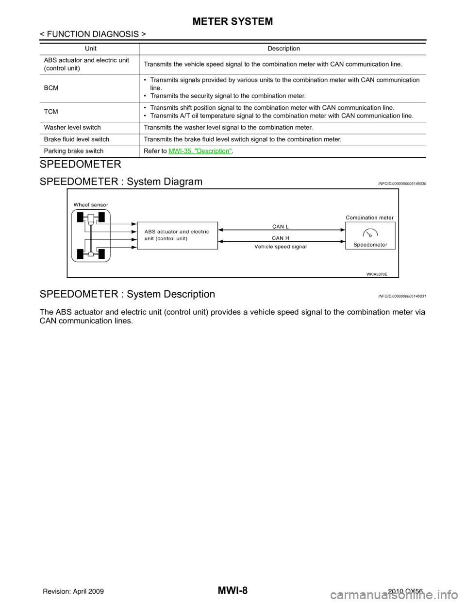
SPEEDOMETER : System DiagramINFOID:0000000005146030
SPEEDOMETER : System DescriptionINFOID:0000000005146031
The ABS actuator and electric unit (control unit) provides a vehicle speed signal to the combination meter via
CAN communication lines.
ABS actuator and electric unit
(control unit) Transmits the vehicle speed signal to the combination meter with CAN communication line.
BCM • Transmits signals provided by various units to the combination meter with CAN communication
line.
• Transmits the security signal to the combination meter.
TCM • Transmits shift position signal to the combination meter with CAN communication line.
• Transmits A/T oil temperature signal to the combination meter with CAN communication line.
Washer level switch Transmits the washer level signal to the combination meter.
Brake fluid level switch Transmits the brake fluid level switch signal to the combination meter.
Parking brake switch Refer to MWI-35, "
Description".
Unit
Description
WKIA5370E
Revision: April 20092010 QX56
Page 2771 of 4210
MWI
METER SYSTEMMWI-9
< FUNCTION DIAGNOSIS >
C
DE
F
G H
I
J
K L
M B A
O P
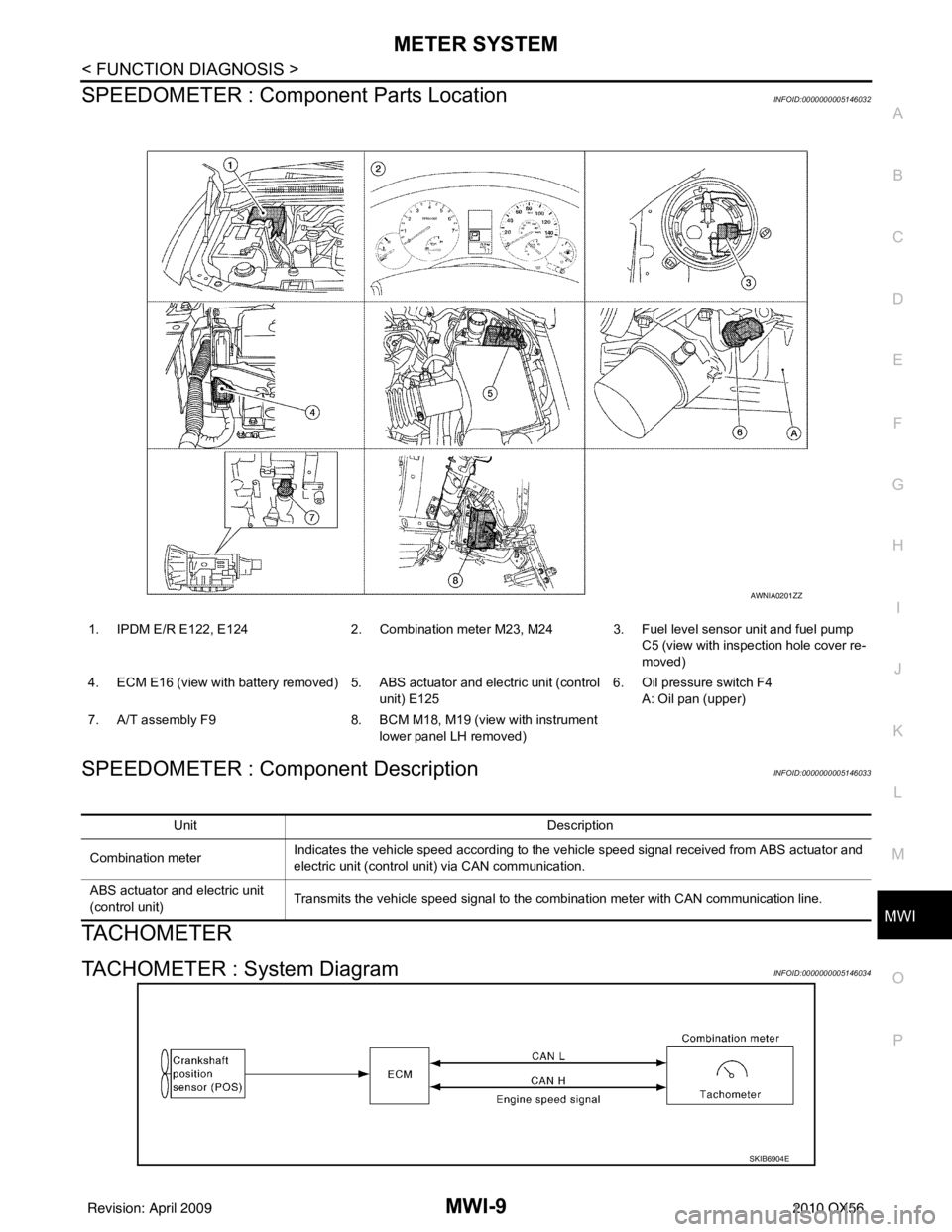
SPEEDOMETER : Compone nt Parts LocationINFOID:0000000005146032
SPEEDOMETER : Component DescriptionINFOID:0000000005146033
TACHOMETER
TACHOMETER : System DiagramINFOID:0000000005146034
1. IPDM E/R E122, E124 2. Combination meter M23, M24 3. Fuel level sensor unit and fuel pump
C5 (view with inspection hole cover re-
moved)
4. ECM E16 (view with battery removed) 5. ABS actuator and electric unit (control unit) E1256. Oil pressure switch F4
A: Oil pan (upper)
7. A/T assembly F9 8. BCM M18, M19 (view with instrument
lower panel LH removed)
AWNIA0201ZZ
Unit Description
Combination meter Indicates the vehicle speed according to the vehicle speed signal received from ABS actuator and
electric unit (control unit) via CAN communication.
ABS actuator and electric unit
(control unit) Transmits the vehicle speed signal to the combination meter with CAN communication line.
SKIB6904E
Revision: April 20092010 QX56
Page 2773 of 4210
MWI
METER SYSTEMMWI-11
< FUNCTION DIAGNOSIS >
C
DE
F
G H
I
J
K L
M B A
O P
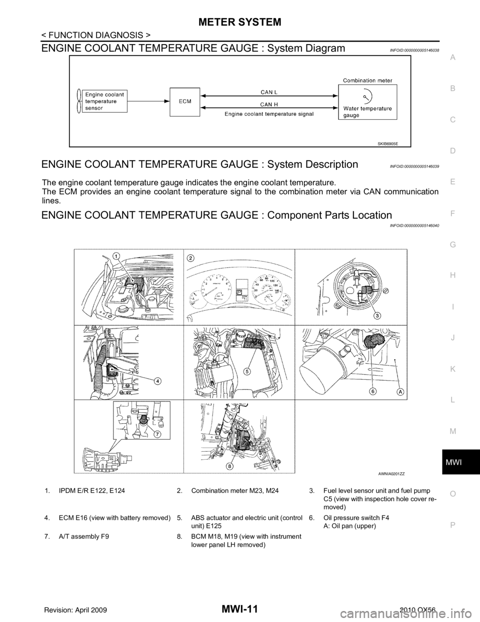
ENGINE COOLANT TEMPERATURE GAUGE : System DiagramINFOID:0000000005146038
ENGINE COOLANT TEMPERATURE GAUGE : System DescriptionINFOID:0000000005146039
The engine coolant temperature gauge indicates the engine coolant temperature.
The ECM provides an engine coolant temperature signal to the combination meter via CAN communication
lines.
ENGINE COOLANT TEMPERATURE GA UGE : Component Parts Location
INFOID:0000000005146040
SKIB6905E
1. IPDM E/R E122, E124 2. Combination meter M23, M24 3. Fuel level sensor unit and fuel pump
C5 (view with inspection hole cover re-
moved)
4. ECM E16 (view with battery removed) 5. ABS actuator and electric unit (control unit) E1256. Oil pressure switch F4
A: Oil pan (upper)
7. A/T assembly F9 8. BCM M18, M19 (view with instrument
lower panel LH removed)
AWNIA0201ZZ
Revision: April 20092010 QX56
Page 2774 of 4210
MWI-12
< FUNCTION DIAGNOSIS >
METER SYSTEM
ENGINE COOLANT TEMPERATURE GAUGE : Component Description
INFOID:0000000005146041
FUEL GAUGE
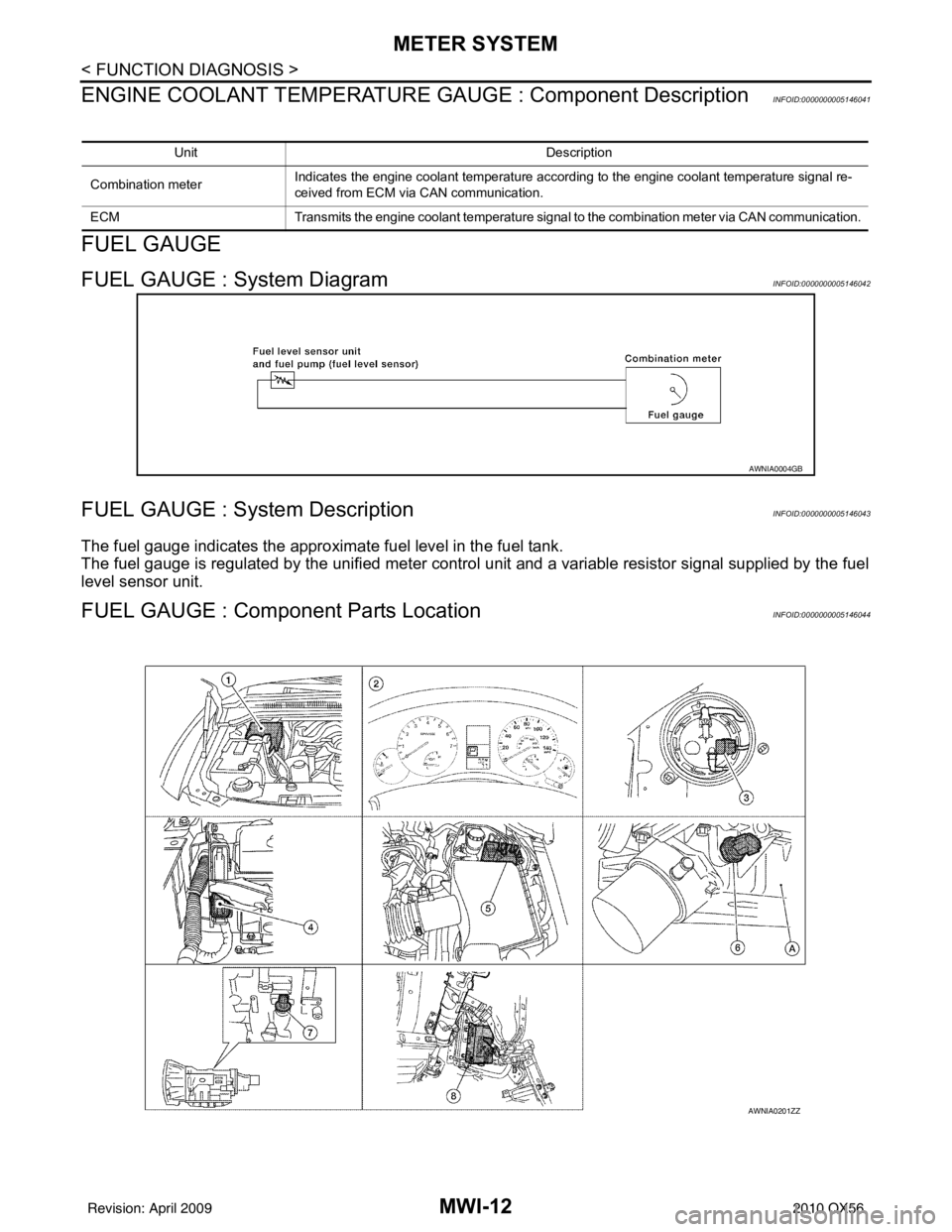
FUEL GAUGE : System DiagramINFOID:0000000005146042
FUEL GAUGE : System DescriptionINFOID:0000000005146043
The fuel gauge indicates the approximate fuel level in the fuel tank.
The fuel gauge is regulated by the unified meter control unit and a variable resistor signal supplied by the fuel
level sensor unit.
FUEL GAUGE : Compone nt Parts LocationINFOID:0000000005146044
Unit Description
Combination meter Indicates the engine coolant temperature according to the engine coolant temperature signal re-
ceived from ECM via CAN communication.
ECM Transmits the engine coolant temperature signal to the combination meter via CAN communication.
AWNIA0004GB
AWNIA0201ZZ
Revision: April 20092010 QX56
Page 2775 of 4210
MWI
METER SYSTEMMWI-13
< FUNCTION DIAGNOSIS >
C
DE
F
G H
I
J
K L
M B A
O PFUEL GAUGE : Component DescriptionINFOID:0000000005146045
ENGINE OIL PRESSURE GAUGE
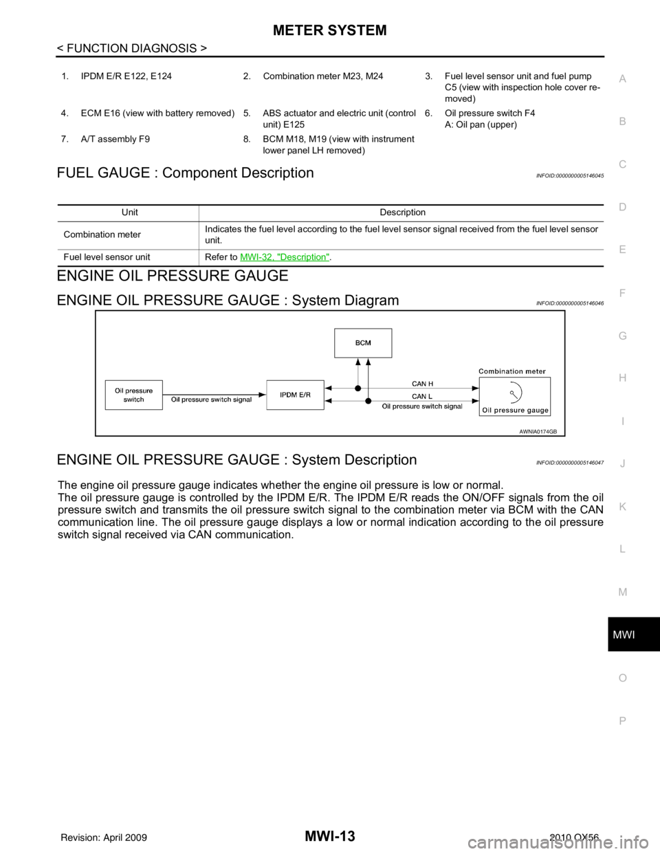
ENGINE OIL PRESSURE GAUGE : System DiagramINFOID:0000000005146046
ENGINE OIL PRESSURE GAUGE : System DescriptionINFOID:0000000005146047
The engine oil pressure gauge indicates whether the engine oil pressure is low or normal.
The oil pressure gauge is controlled by the IPDM E/R. The IPDM E/R reads the ON /OFF signals from the oil
pressure switch and transmits the oil pressure switch signal to the combination meter via BCM with the CAN
communication line. The oil pressure gauge displays a low or normal indication according to the oil pressure
switch signal received via CAN communication.
1. IPDM E/R E122, E124 2. Combination meter M23, M24 3. Fuel level sensor unit and fuel pump
C5 (view with inspection hole cover re-
moved)
4. ECM E16 (view with battery removed) 5. ABS actuator and electric unit (control unit) E1256. Oil pressure switch F4
A: Oil pan (upper)
7. A/T assembly F9 8. BCM M18, M19 (view with instrument
lower panel LH removed)
Unit Description
Combination meter Indicates the fuel level according to the fuel level sensor signal received from the fuel level sensor
unit.
Fuel level sensor unit Refer to MWI-32, "
Description".
AWNIA0174GB
Revision: April 20092010 QX56