Page 1324 of 4210
![INFINITI QX56 2010 Factory Service Manual DLN-242
< SYMPTOM DIAGNOSIS >[REAR FINAL DRIVE: R230]
NOISE, VIBRATION AND HARSHNESS
(NVH) TROUBLESHOOTING
SYMPTOM DIAGNOSIS
NOISE, VIBRATION AND HARSHNESS (NVH) TROUBLESHOOTING
NVH Troubleshooting C INFINITI QX56 2010 Factory Service Manual DLN-242
< SYMPTOM DIAGNOSIS >[REAR FINAL DRIVE: R230]
NOISE, VIBRATION AND HARSHNESS
(NVH) TROUBLESHOOTING
SYMPTOM DIAGNOSIS
NOISE, VIBRATION AND HARSHNESS (NVH) TROUBLESHOOTING
NVH Troubleshooting C](/manual-img/42/57032/w960_57032-1323.png)
DLN-242
< SYMPTOM DIAGNOSIS >[REAR FINAL DRIVE: R230]
NOISE, VIBRATION AND HARSHNESS
(NVH) TROUBLESHOOTING
SYMPTOM DIAGNOSIS
NOISE, VIBRATION AND HARSHNESS (NVH) TROUBLESHOOTING
NVH Troubleshooting ChartINFOID:0000000005148928
Use the chart below to help you find the cause of the sy mptom. If necessary, repair or replace these parts.
×: ApplicableReference page
DLN-253, "
Disassembly and Assembly
"
DLN-253, "
Disassembly and Assembly
"
DLN-253, "
Disassembly and Assembly
"
DLN-270, "
Inspection and Adjustment
"
DLN-270, "
Inspection and Adjustment
"
MA-13, "
Fluids and Lubricants
"
DLN-194, "
NVH Troubleshooting Chart
"
RAX-5, "
NVH Troubleshooting Chart
"
RSU-5, "
NVH Troubleshooting Chart
"
WT-43, "
NVH Troubleshooting Chart
"
WT-43, "
NVH Troubleshooting Chart
"
RAX-5, "
NVH Troubleshooting Chart
"
BR-6, "
NVH Troubleshooting Chart
"
ST-12, "
NVH Troubleshooting Chart
"
Possible cause and SUSPECTED PARTS
Gear tooth rough
Gear contact improper
Tooth surfaces worn
Backlash incorrect
Companion flange excessive runout
Gear oil improper
PROPELLER SHAFT
REAR AXLE
REAR SUSPENSION
TIRES
ROAD WHEEL
DRIVE SHAFT
BRAKES
STEERING
Symptom
Noise××××××× ××××××
Revision: April 20092010 QX56
Page 1881 of 4210
EM-30
< ON-VEHICLE REPAIR >
EXHAUST MANIFOLD AND THREE WAY CATALYST
EXHAUST MANIFOLD AND THREE WAY CATALYST
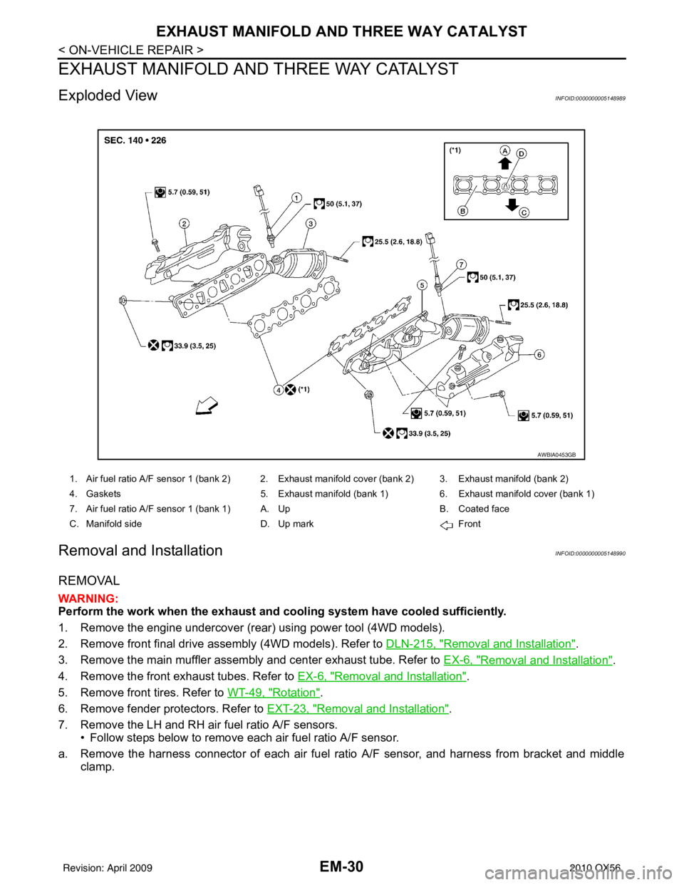
Exploded ViewINFOID:0000000005148989
Removal and InstallationINFOID:0000000005148990
REMOVAL
WARNING:
Perform the work when the exhaust and cooling system have cooled sufficiently.
1. Remove the engine undercover (rear) using power tool (4WD models).
2. Remove front final drive assembly (4WD models). Refer to DLN-215, "
Removal and Installation".
3. Remove the main muffler assembly and center exhaust tube. Refer to EX-6, "
Removal and Installation".
4. Remove the front exhaust tubes. Refer to EX-6, "
Removal and Installation".
5. Remove front tires. Refer to WT-49, "
Rotation".
6. Remove fender protectors. Refer to EXT-23, "
Removal and Installation".
7. Remove the LH and RH air fuel ratio A/F sensors. • Follow steps below to remove each air fuel ratio A/F sensor.
a. Remove the harness connector of each air fuel ra tio A/F sensor, and harness from bracket and middle
clamp.
1. Air fuel ratio A/F sensor 1 (bank 2) 2. Exhaust manifold cover (bank 2) 3. Exhaust manifold (bank 2)
4. Gaskets 5. Exhaust manifold (bank 1) 6. Exhaust manifold cover (bank 1)
7. Air fuel ratio A/F sensor 1 (bank 1) A. Up B. Coated face
C. Manifold side D. Up mark Front
AWBIA0453GB
Revision: April 20092010 QX56
Page 2121 of 4210
ADJUSTMENT AND INSPECTIONEXL-145
< ON-VEHICLE REPAIR >
C
DE
F
G H
I
J
K
M A
B
EXL
N
O P
ON-VEHICLE REPAIR
ADJUSTMENT AND INSPECTION
HEADLAMP
HEADLAMP : Aiming AdjustmentINFOID:0000000005146696
NOTE:
• For details, refer to the regulations in your area.
• If vehicle front body has been repaired and /or the headlamp assembly has been replaced, check headlamp
aiming.
HEADLAMP AIMING
NOTE:
• Before performing aiming adjustment, check the following:
- Ensure all tires are inflated to correct pressure.
- Place vehicle and screen on level surface.
- Ensure there is no load in vehicle other than the driver (or equivalent weight placed in driver's position). Coolant and engine oil filled to correct level, and fuel tank full.
- Confirm spare tire, jack and tools are properly stowed.
- Aim each headlamp individually and ensure other headlamp beam pattern is blocked from screen.
- Use adjusting screw to perform aiming adjustment
WKIA1859E
Revision: April 20092010 QX56
Page 2122 of 4210
EXL-146
< ON-VEHICLE REPAIR >
ADJUSTMENT AND INSPECTION
NOTE:
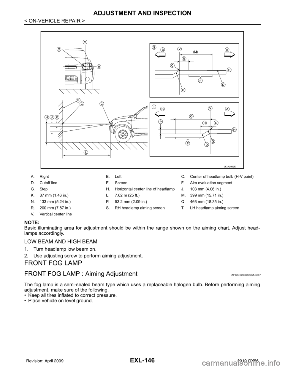
Basic illuminating area for adjustment should be within the range shown on the aiming chart. Adjust head-
lamps accordingly.
LOW BEAM AND HIGH BEAM
1. Turn headlamp low beam on.
2. Use adjusting screw to perform aiming adjustment.
FRONT FOG LAMP
FRONT FOG LAMP : Aiming AdjustmentINFOID:0000000005146697
The fog lamp is a semi-sealed beam type which uses a replaceable halogen bulb. Before performing aiming
adjustment, make sure of the following.
• Keep all tires inflated to correct pressure.
• Place vehicle on level ground.
A. RightB. Left C. Center of headlamp bulb (H-V point)
D. Cutoff line E. ScreenF. Aim evaluation segment
G. Step H. Horizontal center line of headlamp J. 103 mm (4.06 in.)
K. 37 mm (1.46 in.) L. 7.62 m (25 ft.) M. 399 mm (15.71 in.)
N. 133 mm (5.24 in.) P. 53.2 mm (2.09 in.)Q. 466 mm (18.35 in.)
R. 200 mm (7.87 in.) S. RH headlamp aiming screen T. LH headlamp aiming screen
V. Vertical center line
LKIA0809E
Revision: April 20092010 QX56
Page 2171 of 4210
NOISE, VIBRATION AND HARSHNESS (NVH) TROUBLESHOOTINGFAX-5
< SYMPTOM DIAGNOSIS >
CEF
G H
I
J
K L
M A
B
FA X
N
O P
SYMPTOM DIAGNOSIS
NOISE, VIBRATION AND HARSHN ESS (NVH) TROUBLESHOOTING
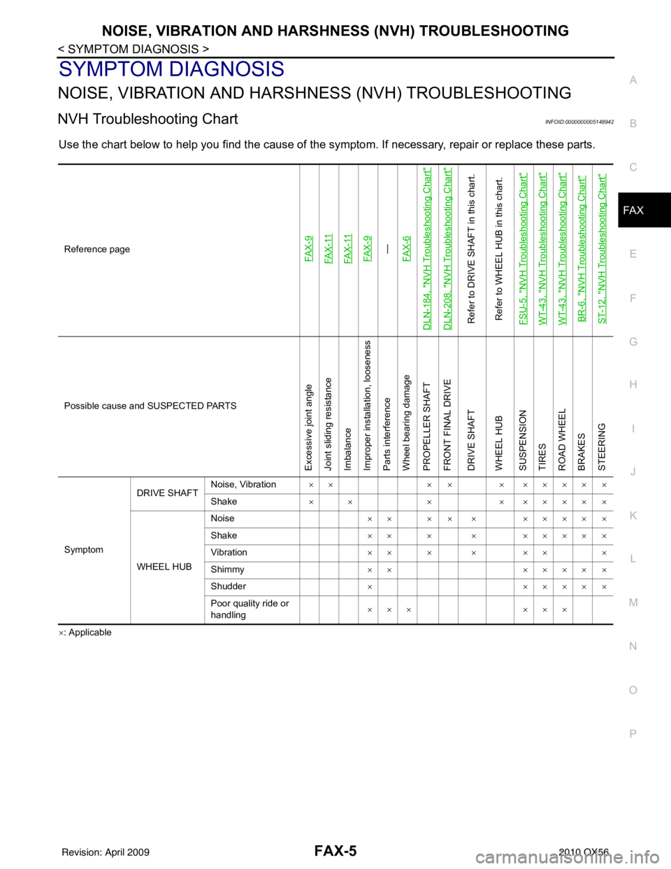
NVH Troubleshooting ChartINFOID:0000000005148942
Use the chart below to help you find t he cause of the symptom. If necessary, repair or replace these parts.
×: ApplicableReference page
FA X - 9FA X - 11FA X - 11FA X - 9—
FA X - 6
DLN-184, "
NVH Troubleshooting Chart
"
DLN-208, "
NVH Troubleshooting Chart
"
Refer to DRIVE SHAFT in this chart.
Refer to WHEEL HUB in this chart.
FSU-5, "
NVH Troubleshooting Chart
"
WT-43, "
NVH Troubleshooting Chart
"
WT-43, "
NVH Troubleshooting Chart
"
BR-6, "
NVH Troubleshooting Chart
"
ST-12, "
NVH Troubleshooting Chart
"
Possible cause and SUSPECTED PARTS
Excessive joint angle
Joint sliding resistance
Imbalance
Improper installation, looseness
Parts interference
Wheel bearing damage
PROPELLER SHAFT
FRONT FINAL DRIVE
DRIVE SHAFT
WHEEL HUB
SUSPENSION
TIRES
ROAD WHEEL
BRAKES
STEERING
Symptom DRIVE SHAFT
Noise, Vibration
×× × × × ×××× ×
Shake × × ×× ×××× ×
WHEEL HUB Noise
×× × × × ×××× ×
Shake ×× × × ×××× ×
Vibration ×× × × ×× ×
Shimmy ×××××× ×
Shudder ×× ××× ×
Poor quality ride or
handling ×××
×××
Revision: April 20092010 QX56
Page 2202 of 4210

PRECAUTIONSFSU-3
< PRECAUTION >
C
DF
G H
I
J
K L
M A
B
FSU
N
O P
5. When the repair work is completed, return the ignition switch to the ″LOCK ″ position before connecting
the battery cables. (At this time, the steering lock mechanism will engage.)
6. Perform a self-diagnosis check of al l control units using CONSULT-III.
PrecautionINFOID:0000000005148104
• When installing the rubber bushings, the final tightening must be done under unladen condition and with the
tires on level ground. Oil will shorten the life of the rubber bushings, so wipe off any spilled oil immediately.
• Unladen condition means the fuel tank, engine coolant and lubricants are at the full specification. The spare
tire, jack, hand tools, and mats are in their designated positions.
• After installing suspension components, check the wheel alignment.
• Lock nuts are not reusable. Always use new lock nuts for installation. New lock nuts are pre-oiled, do not
apply any additional lubrication.
Revision: April 20092010 QX56
Page 2204 of 4210
NOISE, VIBRATION AND HARSHNESS (NVH) TROUBLESHOOTINGFSU-5
< SYMPTOM DIAGNOSIS >
C
DF
G H
I
J
K L
M A
B
FSU
N
O P
SYMPTOM DIAGNOSIS
NOISE, VIBRATION AND HARSHN ESS (NVH) TROUBLESHOOTING
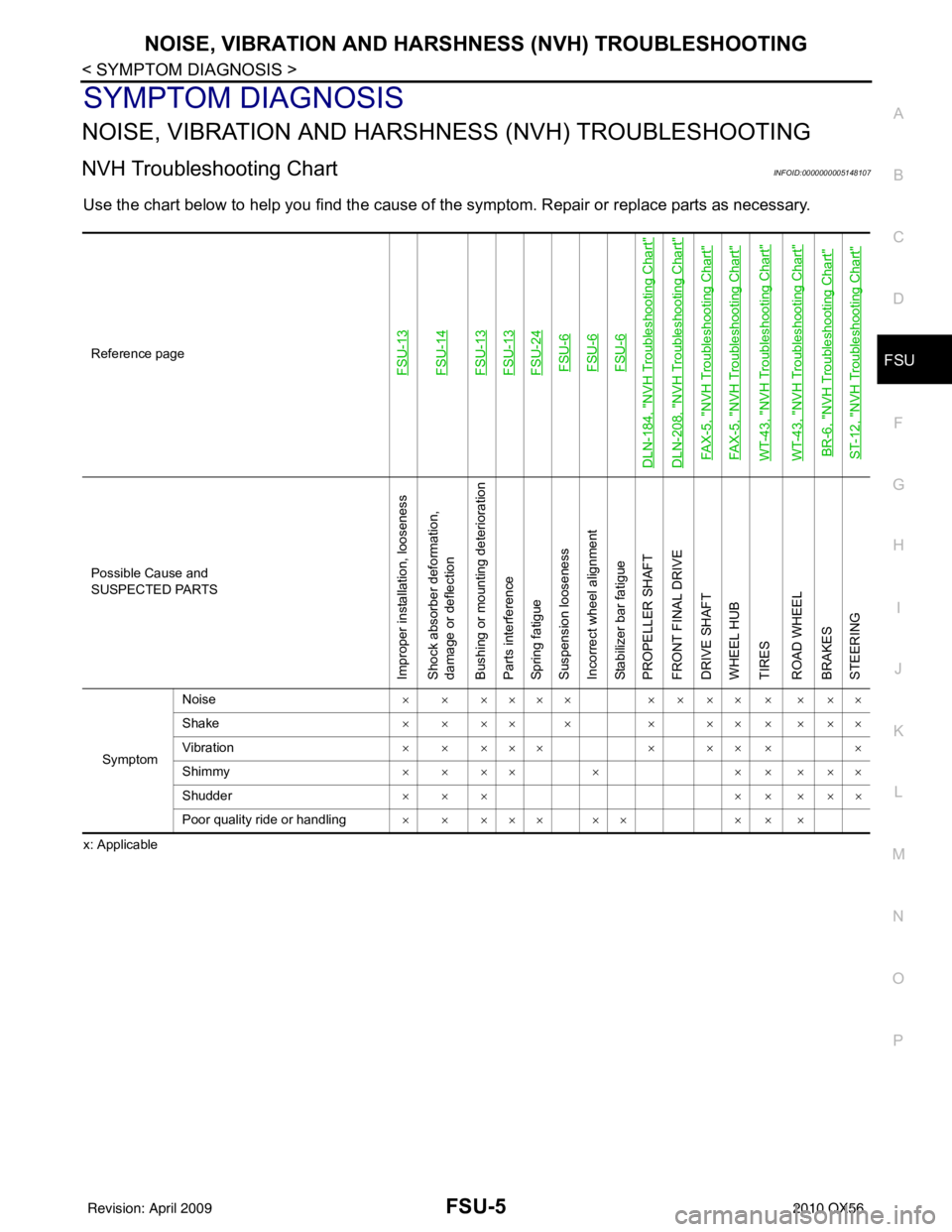
NVH Troubleshooting ChartINFOID:0000000005148107
Use the chart below to help you find the cause of the symptom. Repair or replace parts as necessary.
x: ApplicableReference page
FSU-13FSU-14FSU-13FSU-13FSU-24FSU-6FSU-6FSU-6
DLN-184, "
NVH Troubleshooting Chart
"
DLN-208, "
NVH Troubleshooting Chart
"
FAX-5, "
NVH Troubleshooting Chart
"
FAX-5, "
NVH Troubleshooting Chart
"
WT-43, "
NVH Troubleshooting Chart
"
WT-43, "
NVH Troubleshooting Chart
"
BR-6, "
NVH Troubleshooting Chart
"
ST-12, "
NVH Troubleshooting Chart
"
Possible Cause and
SUSPECTED PARTS
Improper installation, looseness
Shock absorber deformation,
damage or deflection
Bushing or mounting deterioration
Parts interference
Spring fatigue
Suspension looseness
Incorrect wheel alignment
Stabilizer bar fatigue
PROPELLER SHAFT
FRONT FINAL DRIVE
DRIVE SHAFT
WHEEL HUB
TIRES
ROAD WHEEL
BRAKES
STEERING
Symptom
Noise
× × ×××× × × ×× × × ××
Shake × × ×× × × ×× × × ××
Vibration × × ××× × ×× × ×
Shimmy × × ×× × × × × ××
Shudder ××× ×××××
Poor quality ride or handling × × ××× ×× × × ×
Revision: April 20092010 QX56
Page 2205 of 4210
FSU-6
< ON-VEHICLE MAINTENANCE >
ON-VEHICLE SERVICE
ON-VEHICLE MAINTENANCE
ON-VEHICLE SERVICE
Front Suspension PartsINFOID:0000000005148108
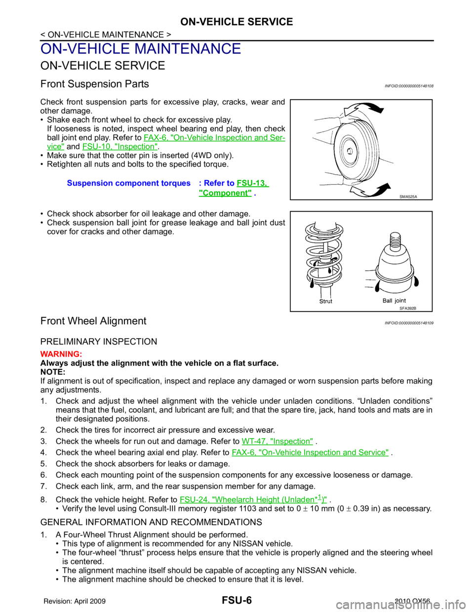
Check front suspension parts for excessive play, cracks, wear and
other damage.
• Shake each front wheel to check for excessive play.If looseness is noted, inspect wheel bearing end play, then check
ball joint end play. Refer to FA X - 6 , "
On-Vehicle Inspection and Ser-
vice" and FSU-10, "Inspection".
• Make sure that the cotter pin is inserted (4WD only).
• Retighten all nuts and bolts to the specified torque.
• Check shock absorber for oil leakage and other damage.
• Check suspension ball joint for grease leakage and ball joint dust cover for cracks and other damage.
Front Wheel AlignmentINFOID:0000000005148109
PRELIMINARY INSPECTION
WARNING:
Always adjust the alignment with the vehicle on a flat surface.
NOTE:
If alignment is out of specificat ion, inspect and replace any damaged or worn suspension parts before making
any adjustments.
1. Check and adjust the wheel alignment with the vehicle under unladen conditions. “Unladen conditions”
means that the fuel, coolant, and lubricant are full; and that the spare tire, jack, hand tools and mats are in
their designated positions.
2. Check the tires for incorrect air pressure and excessive wear.
3. Check the wheels for run out and damage. Refer to WT-47, "
Inspection" .
4. Check the wheel bearing axial end play. Refer to FA X - 6 , "
On-Vehicle Inspection and Service" .
5. Check the shock absorbers for leaks or damage.
6. Check each mounting point of the suspension components for any excessive looseness or damage.
7. Check each link, arm, and the rear suspension member for any damage.
8. Check the vehicle height. Refer to FSU-24, "
Wheelarch Height (Unladen*1)" .
• Verify the level using Consult-III memory register 1103 and set to 0 ± 10 mm (0 ± 0.39 in) as necessary.
GENERAL INFORMATION AND RECOMMENDATIONS
1. A Four-Wheel Thrust Alignment should be performed.
• This type of alignment is recommended for any NISSAN vehicle.
• The four-wheel “thrust” process helps ensure that the vehicle is properly aligned and the steering wheel
is centered.
• The alignment machine itself should be ca pable of accepting any NISSAN vehicle.
• The alignment machine should be checked to ensure that it is level. Suspension component
torques : Refer to FSU-13,
"Component" . SMA525A
SFA392B
Revision: April 20092010 QX56