2010 INFINITI QX56 air filter
[x] Cancel search: air filterPage 2730 of 4210
MA-26
< ON-VEHICLE MAINTENANCE >
CHASSIS AND BODY MAINTENANCE
CHASSIS AND BODY MAINTENANCE
IN-CABIN MICROFILTER
IN-CABIN MICROFILTER : Removal and InstallationINFOID:0000000005403149
REPLACEMENT PROCEDURE
1. Remove the glove box assembly from the instrument panel. Refer to IP-17, "Removal and Installation".
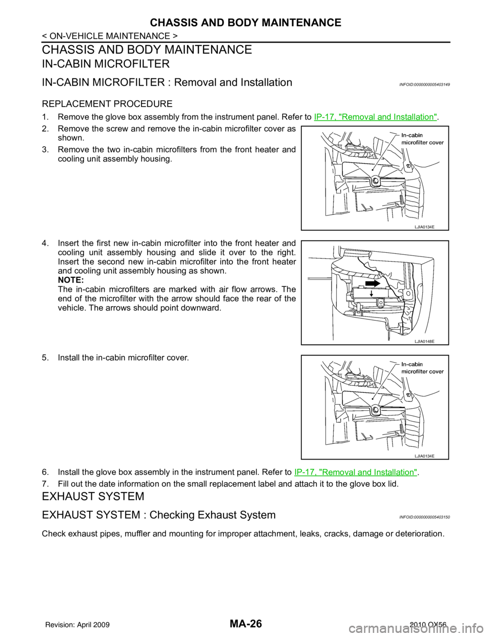
2. Remove the screw and remove the in-cabin microfilter cover as shown.
3. Remove the two in-cabin microf ilters from the front heater and
cooling unit assembly housing.
4. Insert the first new in-cabin micr ofilter into the front heater and
cooling unit assembly housing and slide it over to the right.
Insert the second new in-cabin mi crofilter into the front heater
and cooling unit assembly housing as shown.
NOTE:
The in-cabin microfilters are marked with air flow arrows. The
end of the microfilter with the arro w should face the rear of the
vehicle. The arrows should point downward.
5. Install the in-cabin microfilter cover.
6. Install the glove box assembly in the instrument panel. Refer to IP-17, "
Removal and Installation".
7. Fill out the date information on the small replac ement label and attach it to the glove box lid.
EXHAUST SYSTEM
EXHAUST SYSTEM : Checking Exhaust SystemINFOID:0000000005403150
Check exhaust pipes, muffler and mounting for improper attachment, leaks, cracks, damage or deterioration.
LJIA0134E
LJIA0148E
LJIA0134E
Revision: April 20092010 QX56
Page 3848 of 4210

A/T FLUID COOLERTM-153
< ON-VEHICLE MAINTENANCE >
CEF
G H
I
J
K L
M A
B
TM
N
O P
13. Flush each steel line from the cooler side back toward the A/T by spraying Transmission Cooler Cleaner in a continuous stream for 5 seconds.
14. Blow compressed air regulated to 490 - 883 kPa (5 - 9 kg/cm
2, 71 - 128 psi) through each steel line from
the cooler side back toward the A/T for 10 seconds to force out any remaining fluid.
15. Ensure all debris is removed from the steel cooler lines.
16. Ensure all debris is removed from the banjo bolts and fittings.
17. Perform A/T fluid cooler diagnosis procedure.
A/T FLUID COOLER DIAGNOSIS PROCEDURE
NOTE:
Insufficient cleaning of the cooler inlet hose exte rior may lead to inaccurate debris identification.
1. Position a drain pan under the A/T inlet and outlet fluid cooler tube to cooler hose connection.
2. Clean the exterior and tip of the cooler inlet hose.
3. Put a different color matching mark on each cooler tube to cooler hose connection to aid in assembly. CAUTION:
Use paint to make the matching mark. Do not damage the tubes or hose.
4. Disconnect the fluid cooler inle t and outlet rubber hoses from the
steel cooler tubes.
NOTE:
Replace the cooler hoses if rubber material from the hose
remains on the tube fitting.
5. Insert the extension adapter hose of a can of Transmission Cooler Cleaner (Nissan P/N 999MP-AM006) into the cooler out-
let hose.
CAUTION:
• Wear safety glasses and rubber gloves when spraying the
Transmission Cooler Cleaner.
• Spray cooler cleaner only with adequate ventilation.
• Avoid contact with eyes and skin.
• Do not breath vapors or spray mist.
6. Hold the hose and can as high as possible and spray Transmis- sion Cooler Cleaner in a continuous stream into the cooler outlet
hose until fluid flows out of the cooler inlet hose for 5 seconds.
7. Tie a common white, basket-type coffee filter to the end of the cooler inlet hose.
SCIA3830E
SCIA3831E
SCIA3833E
Revision: April 20092010 QX56
Page 3849 of 4210
TM-154
< ON-VEHICLE MAINTENANCE >
A/T FLUID COOLER
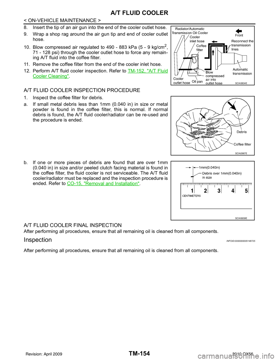
8. Insert the tip of an air gun into the end of the cooler outlet hose.
9. Wrap a shop rag around the air gun tip and end of cooler outlethose.
10. Blow compressed air regulated to 490 - 883 kPa (5 - 9 kg/cm
2,
71 - 128 psi) through the cooler outlet hose to force any remain-
ing A/T fluid into the coffee filter.
11. Remove the coffee filter from the end of the cooler inlet hose.
12. Perform A/T fluid cooler inspection. Refer to TM-152, "
A/T Fluid
Cooler Cleaning".
A/T FLUID COOLER INSPECTION PROCEDURE
1. Inspect the coffee filter for debris.
a. If small metal debris less than 1mm (0.040 in) in size or metal
powder is found in the coffee filter, this is normal. If normal
debris is found, the A/T fluid cooler/radiator can be re-used and
the procedure is ended.
b. If one or more pieces of debris are found that are over 1mm (0.040 in) in size and/or peeled clutch facing material is found in
the coffee filter, the fluid cooler is not serviceable. The A/T fluid
cooler/radiator must be replaced and the inspection procedure is
ended. Refer to CO-15, "
Removal and Installation".
A/T FLUID COOLER FINAL INSPECTION
After performing all procedures, ensure that all remaining oil is cleaned from all components.
InspectionINFOID:0000000005148725
After performing all procedures, ensure that all remaining oil is cleaned from all components.
SCIA3834E
SCIA2967E
SCIA5659E
Revision: April 20092010 QX56
Page 3963 of 4210

VTL-1
VENTILATION, HEATER & AIR CONDITIONER
C
DE
F
G H
J
K L
M
SECTION VTL
A
B
VTL
N
O P
CONTENTS
VENTILATION SYSTEM
PRECAUTION ....... ........................................2
PRECAUTIONS .............................................. .....2
Precaution for Supplemental Restraint System
(SRS) "AIR BAG" and "SEAT BELT PRE-TEN-
SIONER" ............................................................. ......
2
Precaution Necessary for Steering Wheel Rota-
tion After Battery Disconnect ............................... ......
2
Precaution for Working with HFC-134a (R-134a) ......3
Precaution for Procedure without Cowl Top Cover ......3
PREPARATION ............................................4
PREPARATION .............................................. .....4
Commercial Service Tool .................................... ......4
FUNCTION DIAGNOSIS ...............................5
IN-CABIN MICROFILTER .............................. .....5
Description .......................................................... ......5
ON-VEHICLE MAINTENANCE .....................6
IN-CABIN MICROFILTER .............................. .....6
Removal and Installation ...........................................6
ON-VEHICLE REPAIR .... ..............................7
CONTROL UNIT ..................................................7
Removal and Installation ...........................................7
IN-VEHICLE SENSOR ................................... .....9
Removal and Installation ...........................................9
OPTICAL SENSOR ........................................ ....10
Removal and Installation .........................................10
INTAKE SENSOR ..............................................11
Removal and Installation .........................................11
BLOWER MOTOR .......................................... ....12
Component .......................................................... ....12
Removal and Installation .........................................12
VARIABLE BLOWER CONTROL .....................14
Components ............................................................14
Removal and Installation .........................................15
HEATER & COOLING UNIT ASSEMBLY ........16
Component ..............................................................16
Removal and Installation .........................................17
EVAPORATOR .................................................19
Removal and Installation for Front Evaporator ........19
Removal and Installation for Rear Evaporator .........20
EXPANSION VALVE .........................................22
Removal and Installation for Rear Expansion
Valve .................................................................... ....
22
HEATER CORE .................................................23
Component ..............................................................23
Removal and Installation .........................................24
DEFROSTER DOOR MOTOR ..........................26
Removal and Installation .........................................26
INTAKE DOOR MOTOR ...................................27
Removal and Installation .........................................27
MODE DOOR MOTOR ......................................28
Components ............................................................28
Removal and Installation .........................................29
AIR MIX DOOR MOTOR ...................................30
Component ..............................................................30
Removal and Installation .........................................31
DUCTS AND GRILLES .....................................33
Component ..............................................................33
Removal and Installation .........................................36
Revision: April 20092010 QX56
Page 3967 of 4210
IN-CABIN MICROFILTERVTL-5
< FUNCTION DIAGNOSIS >
C
DE
F
G H
J
K L
M A
B
VTL
N
O P
FUNCTION DIAGNOSIS
IN-CABIN MICROFILTER
DescriptionINFOID:0000000005147603
FUNCTION
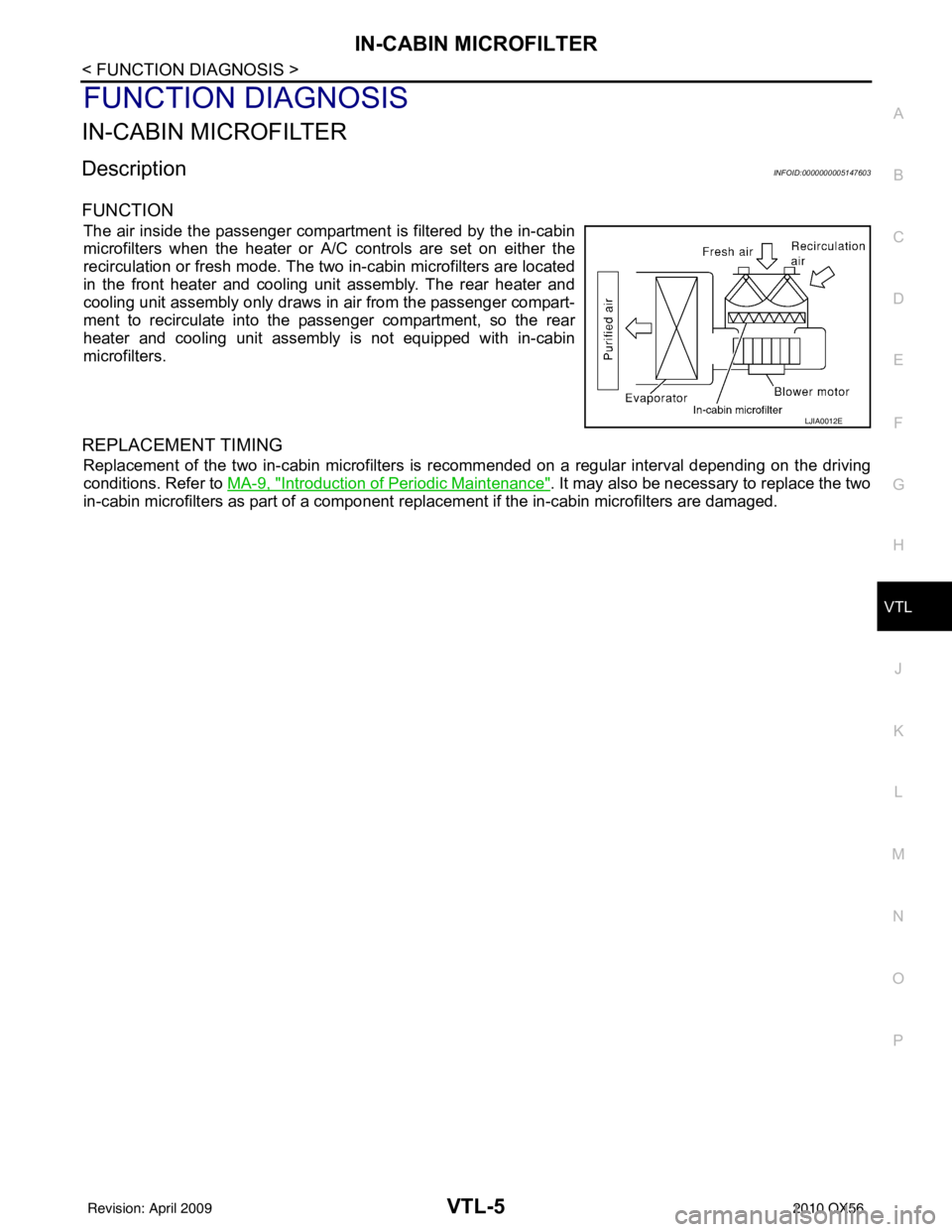
The air inside the passenger compartment is filtered by the in-cabin
microfilters when the heater or A/C controls are set on either the
recirculation or fresh mode. The two in-cabin microfilters are located
in the front heater and cooling unit assembly. The rear heater and
cooling unit assembly only draws in air from the passenger compart-
ment to recirculate into the passenger compartment, so the rear
heater and cooling unit assembly is not equipped with in-cabin
microfilters.
REPLACEMENT TIMING
Replacement of the two in-cabin microfilters is recommended on a regular interval depending on the driving
conditions. Refer to MA-9, "
Introduction of Periodic Maintenance". It may also be necessary to replace the two
in-cabin microfilters as part of a component r eplacement if the in-cabin microfilters are damaged.
LJIA0012E
Revision: April 20092010 QX56
Page 3968 of 4210
VTL-6
< ON-VEHICLE MAINTENANCE >
IN-CABIN MICROFILTER
ON-VEHICLE MAINTENANCE
IN-CABIN MICROFILTER
Removal and InstallationINFOID:0000000005147604
REPLACEMENT PROCEDURE
1. Remove the glove box assembly from the instrument panel. Refer to IP-17, "Removal and Installation".
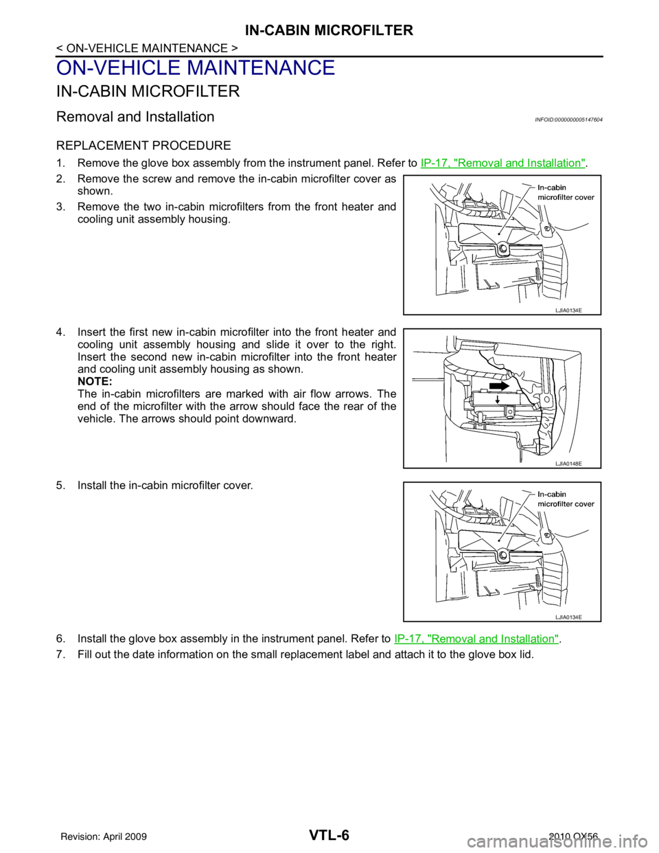
2. Remove the screw and remove the in-cabin microfilter cover as shown.
3. Remove the two in-cabin microf ilters from the front heater and
cooling unit assembly housing.
4. Insert the first new in-cabin micr ofilter into the front heater and
cooling unit assembly housing and slide it over to the right.
Insert the second new in-cabin mi crofilter into the front heater
and cooling unit assembly housing as shown.
NOTE:
The in-cabin microfilters are marked with air flow arrows. The
end of the microfilter with the arro w should face the rear of the
vehicle. The arrows should point downward.
5. Install the in-cabin microfilter cover.
6. Install the glove box assembly in the instrument panel. Refer to IP-17, "
Removal and Installation".
7. Fill out the date information on the small replac ement label and attach it to the glove box lid.
LJIA0134E
LJIA0148E
LJIA0134E
Revision: April 20092010 QX56
Page 3987 of 4210
HEATER COREVTL-25
< ON-VEHICLE REPAIR >
C
DE
F
G H
J
K L
M A
B
VTL
N
O P
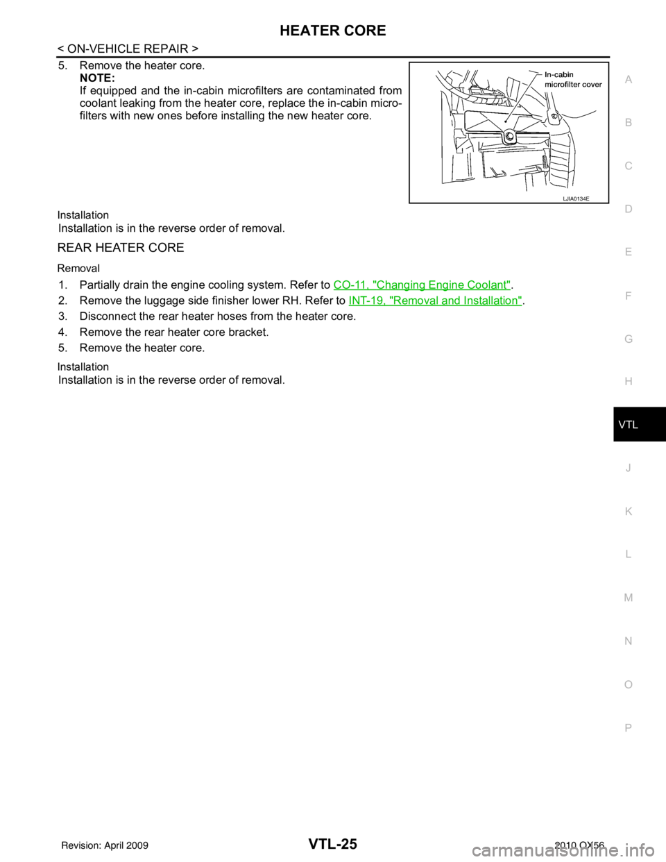
5. Remove the heater core. NOTE:
If equipped and the in-cabin microfilters are contaminated from
coolant leaking from the heater core, replace the in-cabin micro-
filters with new ones before installing the new heater core.
Installation
Installation is in the reverse order of removal.
REAR HEATER CORE
Removal
1. Partially drain the engine cooling system. Refer to CO-11, "Changing Engine Coolant".
2. Remove the luggage side finisher lower RH. Refer to INT-19, "
Removal and Installation".
3. Disconnect the rear heater hoses from the heater core.
4. Remove the rear heater core bracket.
5. Remove the heater core.
Installation
Installation is in the reverse order of removal.
LJIA0134E
Revision: April 20092010 QX56