Page 148 of 4210

ADP-134
< ECU DIAGNOSIS >
DRIVER SEAT CONTROL UNIT
NOTE:
The front seat LH position and pedal adjustment functions (see the following table) operate simultaneously in
the order of priority.
*: In conjunction with sliding the seat, the door mirrors are positioned.
CANCEL OF FAIL-SAFE MODE
The mode is cancelled when the A/T selector lever is shifted to P position from any other position.
DTC IndexINFOID:0000000005147579
*1:
• 0: Current malfunction is present
• 1-39: Displayed if any previous malfunction is present when current condition is normal. The numeral value increases by one at each
IGN ON to OFF cycle from 1 to 39. The counter remains at 39 even if the number of cycles exceeds it. However, the counter is re set
to 1 if any malfunction is detected again, the normal operation is resumed and the ignition switch is turned from OFF to ON. OPERATED PORTION
T2
Seat sliding Approx. 0.1 sec.
Seat reclining Same as above
Seat lifting (Front) Same as above
Seat lifting (Rear) Same as above
Pedal adjust Same as above
Priority Function PriorityFunction
1 Seat sliding, (door mirro r LH/RH)* 4Seat lifter-FR
2 Pedal 5Seat lifter-RR
3 Seat reclining
CONSULT-III
display Timing
*1
Item
Reference page
Current mal-
function Previous mal-
function
CAN COMM CIRCUIT
[U1000] 0
1-39 CAN communication ADP-31
SEAT SLIDE
[B2112]0
1-39 Seat slide motor output ADP-32
SEAT RECLINING
[B2113]0
1-39 Seat reclin ing motor output ADP-33
SEAT LIFTER FRONT
[B2114] 0
1-39 Seat lifting motor front output ADP-36
SEAT LIFTER REAR
[B2115]0
1-39 Seat lifting motor rear output ADP-36
TILT MOTOR
[B2116]0
1-39 Tilt motor output ADP-105
ADJ PEDAL MOTOR
[B2117]0
1-39 Pedal adjusting motor output ADP-36
TILT SENSOR
[B2118]0
1-39 Tilt sensor input ADP-38
ADJ PEDAL SENSOR
[B2120]0
1-39 Pedal adjusting sensor input ADP-36
DETENT SW
[B2126]0
1-39 Park position switch condition ADP-42
UART COMM
[B2128]0
1-39 UART communication ADP-44
Revision: April 20092010 QX56
Page 149 of 4210

AUTOMATIC DRIVE POSITIONER CONTROL UNITADP-135
< ECU DIAGNOSIS >
C
DE
F
G H
I
K L
M A
B
ADP
N
O P
AUTOMATIC DRIVE POSITIONER CONTROL UNIT
Reference ValueINFOID:0000000005147580
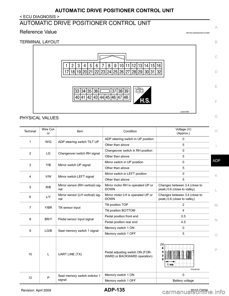
TERMINAL LAYOUT
PHYSICAL VALUES
LIIA2449E
Te r m i n a l Wire Col-
or Item
Condition Voltage (V)
(Approx.)
1 W/G ADP steering switch TILT UP ADP steering switch in UP position
0
Other than above 5
2 LG Changeover switch RH signal Changeover switch in RH position
0
Other than above 5
3 Y/B Mirror switch UP signal Mirror switch in UP position
0
Other than above 5
4 V/W Mirror switch LEFT signal Mirror switch in LEFT position
0
Other than above 5
5R/B Mirror sensor (
RH vertical) sig-
nal Mirror motor RH is operated UP or
DOWN Changes between 3.4 (close to
peak) 0.6 (close to valley)
6L/Y Mirror sensor (L
H vertical) sig-
nal Mirror motor LH is operated UP or
DOWN Changes between 3.4 (close to
peak) 0.6 (close to valley)
7 Y/BR Tilt sensor input Tilt position TOP
2
Tilt position BOTTOM 4
8 BR/Y Pedal sensor input signal Pedal position front end
0.5
Pedal position rear end 4.5
9 LG/B Seat memory switch 1 signal Memory switch 1 ON
0
Memory switch 1 OFF 5
10 L UART LINE (TX) Pedal adjusting switch ON (FOR-
WARD or BACKWARD operation)
12 P Seat memory switch indictor 1
signal Memory switch 1 ON
0
Memory switch 1 OFF Battery voltage
PIIA4813E
Revision: April 20092010 QX56
Page 150 of 4210

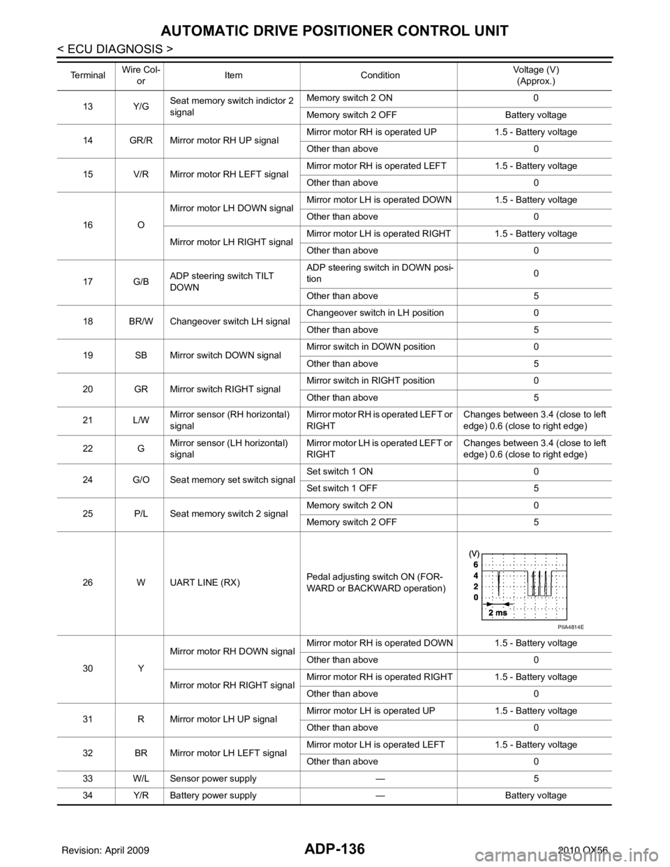
ADP-136
< ECU DIAGNOSIS >
AUTOMATIC DRIVE POSITIONER CONTROL UNIT
13 Y/GSeat memory switch indictor 2
signal Memory switch 2 ON
0
Memory switch 2 OFF Battery voltage
14 GR/R Mirror motor RH UP signal Mirror motor RH is operated UP
1.5 - Battery voltage
Other than above 0
15 V/R Mirror motor RH LEFT signal Mirror motor RH is operated LEFT
1.5 - Battery voltage
Other than above 0
16 O Mirror motor LH
DOWN signal Mirror motor LH is operated DOWN 1.5 - Battery voltage
Other than above
0
Mirror motor LH RIGHT signal Mirror motor LH is operated RIGHT 1.5 - Battery voltage
Other than above
0
17 G/B ADP steering switch TILT
DOWN ADP steering switch in DOWN posi-
tion
0
Other than above 5
18 BR/W Changeover switch LH signal Changeover switch in LH position
0
Other than above 5
19 SB Mirror switch DOWN signal Mirror switch in DOWN position
0
Other than above 5
20 GR Mirror switch RIGHT signal Mirror switch in RIGHT position
0
Other than above 5
21 L/W Mirror sensor (RH horizontal)
signal Mirror motor RH is operated LEFT or
RIGHT Changes between 3.4 (close to left
edge) 0.6 (close to right edge)
22 G Mirror sensor (LH horizontal)
signal Mirror motor LH is operated LEFT or
RIGHT Changes between 3.4 (close to left
edge) 0.6 (close to right edge)
24 G/O Seat memory set switch signal Set switch 1 ON
0
Set switch 1 OFF 5
25 P/L Seat memory switch 2 signal Memory switch 2 ON
0
Memory switch 2 OFF 5
26 W UART LINE (RX) Pedal adjusting switch ON (FOR-
WARD or BACKWARD operation)
30 Y Mirror motor RH DOWN signal
Mirror motor RH is operated DOWN 1.5 - Battery voltage
Other than above
0
Mirror motor RH RIGHT signal Mirror motor RH is operated RIGHT 1.5 - Battery voltage
Other than above
0
31 R Mirror motor LH UP signal Mirror motor LH is operated UP
1.5 - Battery voltage
Other than above 0
32 BR Mirror motor LH LEFT signal Mirror motor LH is operated LEFT
1.5 - Battery voltage
Other than above 0
33 W/L Sensor power supply —5
34 Y/R Battery power supply —Battery voltage
Te r m i n a l
Wire Col-
or Item
Condition Voltage (V)
(Approx.)
PIIA4814E
Revision: April 20092010 QX56
Page 151 of 4210
AUTOMATIC DRIVE POSITIONER CONTROL UNITADP-137
< ECU DIAGNOSIS >
C
DE
F
G H
I
K L
M A
B
ADP
N
O P
35 R Tilt motor UP signal ADP steering switch in UP position Battery voltage
Other than above
0
37 G Pedal adjust motor FORWARD
signal Pedal adjust motor FORWARD op-
eration (Motor operated)
Battery voltage
Other than above 0
39 L/B Battery power supply —Battery voltage
40 B/W Ground —0
41 W/G Sensor ground —0
42 V Tilt motor DOWN signal ADP steering switch in DOWN posi-
tion
Battery voltage
Other than above 0
45 R Pedal adjust motor BACK-
WARD signal Pedal adjust motor BACKWARD op-
eration (Motor operated)
Battery voltage
Other than above 0
48 B Ground —0
Te r m i n a l
Wire Col-
or Item
Condition Voltage (V)
(Approx.)
Revision: April 20092010 QX56
Page 152 of 4210
ADP-138
< ECU DIAGNOSIS >
AUTOMATIC DRIVE POSITIONER CONTROL UNIT
Wiring Diagram
INFOID:0000000005370308
ABJWA0085GB
Revision: April 20092010 QX56
Page 153 of 4210
AUTOMATIC DRIVE POSITIONER CONTROL UNITADP-139
< ECU DIAGNOSIS >
C
DE
F
G H
I
K L
M A
B
ADP
N
O P
ABJWA0086GB
Revision: April 20092010 QX56
Page 154 of 4210
ADP-140
< ECU DIAGNOSIS >
AUTOMATIC DRIVE POSITIONER CONTROL UNIT
ABJWA0087GB
Revision: April 20092010 QX56
Page 155 of 4210
AUTOMATIC DRIVE POSITIONER CONTROL UNITADP-141
< ECU DIAGNOSIS >
C
DE
F
G H
I
K L
M A
B
ADP
N
O P
ABJWA0088GB
Revision: April 20092010 QX56