2010 INFINITI QX56 fuel
[x] Cancel search: fuelPage 2786 of 4210
![INFINITI QX56 2010 Factory Service Manual MWI-24
< FUNCTION DIAGNOSIS >
DIAGNOSIS SYSTEM (METER)
X: Applicable
Display item [Unit]MAIN
SIGNALS SELECTION
FROM MENU Description
SPEED METER [km/h] or [mph] X X Displays the value of vehicle spee INFINITI QX56 2010 Factory Service Manual MWI-24
< FUNCTION DIAGNOSIS >
DIAGNOSIS SYSTEM (METER)
X: Applicable
Display item [Unit]MAIN
SIGNALS SELECTION
FROM MENU Description
SPEED METER [km/h] or [mph] X X Displays the value of vehicle spee](/manual-img/42/57032/w960_57032-2785.png)
MWI-24
< FUNCTION DIAGNOSIS >
DIAGNOSIS SYSTEM (METER)
X: Applicable
Display item [Unit]MAIN
SIGNALS SELECTION
FROM MENU Description
SPEED METER [km/h] or [mph] X X Displays the value of vehicle speed signal.
SPEED OUTPUT [km/h] or [mph] X XDisplays the value of vehicle speed signal, which is transmitted to
each unit with
CAN communication.
TACHO METER [rpm] XX Displays the value of engine speed signal, which is input from ECM.
FUEL METER [lit.] XXDisplays the value, which processes a resistance signal from fuel
gauge.
W TEMP METER [ °C] or [° F] X XDisplays the value of engine coolant temperature signal, which is in-
put from ECM.
ABS W/L [ON/OFF] X Displays [ON/OFF] condition of ABS warning lamp.
VDC/TCS IND [ON/OFF] X Displays [ON/OFF] condition of VDC OFF indicator lamp.
SLIP IND [ON/OFF] X Displays [ON/OFF] condition of SLIP indicator lamp.
BRAKE W/L [ON/OFF] X Displays [ON/OFF] condition of brake warning lamp.*
DOOR W/L [ON/OFF] X Displays [ON/OFF] condition of door warning lamp.
TRUNK W/L [ON/OFF] X Displays [ON/OFF] condition of glass hatch warning lamp.
HI-BEAM IND [ON/OFF] X Displays [ON/OFF] condition of high beam indicator.
TURN IND [ON/OFF] X Displays [ON/OFF] conditio n of turn indicator.
OIL W/L [ON/OFF] X Displays [ON/OFF] condition of oil pressure warning lamp.
C-ENG W/L [ON/OFF] X Displays [ON/OFF] condition of malfunction indicator lamp.
CRUISE IND [ON/OFF] X Displays [ON/OFF] condition of CRUISE indicator.
SET IND [ON/OFF] X Displays [ON/OFF] condition of SET indicator.
AT CHECK W/L [ON/OFF] X Displays [ON/OFF] condition of AT CHECK warning lamp.
FUEL W/L [ON/OFF] XX Displays [ON/OFF] condition of low-fuel warning lamp.
AIR PRES W/L [ON/OFF] X Displays [ON/OFF] condition of tire pressure warning lamp.
KEY G/Y W/L [ON/OFF] X Displays [ON/OFF] condition of key green warning lamp.
KEY R W/L [ON/OFF] X Displays [ON/OFF] condition of key red warning lamp.
KEY KNOB W/L [ON/OFF] X Displays [ON/OFF] condition of key knob warning lamp.
M RANGE SW [ON/OFF] XX Displays [ON/OFF] condition of manual mode range switch.
NM RANGE SW [ON/OFF] XXDisplays [ON/OFF] condition of except for manual mode range
switch.
AT SFT UP SW [ON/OFF] XX Displays [ON/OFF] condition of A/T shift-up switch.
AT SFT DWN SW [ON/OFF] XX Displays [ON/OF F] condition of A/T shift-down switch.
DISTANCE [km] or [mile] XXDisplays the value, which is calculated by vehicle speed signal, fuel
gauge and fuel consumption from ECM.
BUZZER [ON/OFF] XX Displays [ON/ OFF] condition of buzzer.
BRAKE SW [ON/OFF] X Indicates [ON/OFF] condition of parking brake switch.
AT-M GEAR [1, 2, 3, 4] XX Indicates [1, 2, 3, 4] condition of A/T manual mode gear position.
P RANGE IND [ON/OFF] XX Indicates [ON/OFF] condition of A/T shift P range indicator.
R RANGE IND [ON/OFF] XX Indicates [ON/OFF] condition of A/T shift R range indicator.
N RANGE IND [ON/OFF] XX Indicates [ON/OFF] condition of A/T shift N range indicator.
D RANGE IND [ON/OFF] XX Indicates [ON/OFF] condition of A/T shift D range indicator.
4 RANGE IND [ON/OFF] XX Indicates [ON/OFF] condition of A/T shift 4 range indicator.
3 RANGE IND [ON/OFF] XX Indicates [ON/OFF] condition of A/T shift 3 range indicator.
2 RANGE IND [ON/OFF] XX Indicates [ON/OFF] condition of A/T shift 2 range indicator.
1 RANGE IND [ON/OFF] XX Indicates [ON/OFF] condition of A/T shift 1range indicator.
Revision: April 20092010 QX56
Page 2794 of 4210
MWI-32
< COMPONENT DIAGNOSIS >
FUEL LEVEL SENSOR SIGNAL CIRCUIT
FUEL LEVEL SENSOR SIGNAL CIRCUIT
DescriptionINFOID:0000000005146081
The fuel level sensor unit and fuel pump detects the approximate fuel level in the fuel tank and transmits the
fuel level signal to the combination meter.
Component Function CheckINFOID:0000000005146082
1.COMBINATION METER INPUT SIGNAL
1. Select “METER/M&A” on CONSULT-III.
2. Using “FUEL METER” of “DAT A MONITOR”, compare the value of DATA MONITOR with fuel gauge
pointer of combination meter.
Does the data monitor value approximately match the fuel gauge indication?
YES >> Inspection End.
NO >> Replace combination meter. Refer to MWI-100, "
Removal and Installation".
Diagnosis ProcedureINFOID:0000000005146083
Regarding Wiring Diagram information, refer to MWI-41, "Wiring Diagram".
1.CHECK HARNESS CONNECTOR
1. Turn ignition switch OFF.
2. Check combination meter and fuel level sensor uni t terminals (meter-side and harness-side) for poor con-
nection.
Is the inspection result normal?
YES >> GO TO 2
NO >> Repair or replace terminals or connectors.
2.CHECK FUEL LEVEL SENSOR UNIT CIRCUIT
1. Disconnect combination meter connector and fuel level sensor unit connector.
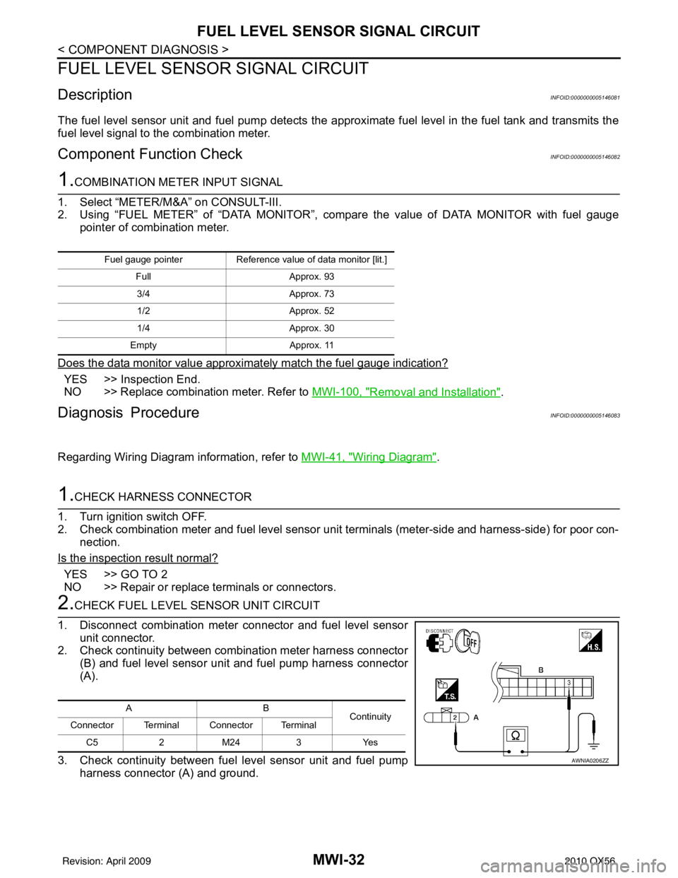
2. Check continuity between combination meter harness connector
(B) and fuel level sensor uni t and fuel pump harness connector
(A).
3. Check continuity between fuel level sensor unit and fuel pump harness connector (A) and ground.
Fuel gauge pointer Reference value of data monitor [lit.]
Full Approx. 93
3/4 Approx. 73
1/2 Approx. 52
1/4 Approx. 30
Empty Approx. 11
AB
Continuity
Connector Terminal Connector Terminal
C5 2 M24 3 Yes
AWNIA0206ZZ
Revision: April 20092010 QX56
Page 2795 of 4210
MWI
FUEL LEVEL SENSOR SIGNAL CIRCUITMWI-33
< COMPONENT DIAGNOSIS >
C
DE
F
G H
I
J
K L
M B A
O P
Is the inspection result normal?
YES >> GO TO 3
NO >> Repair harness or connector.
3.CHECK FUEL LEVEL SENS OR UNIT GROUND CIRCUIT
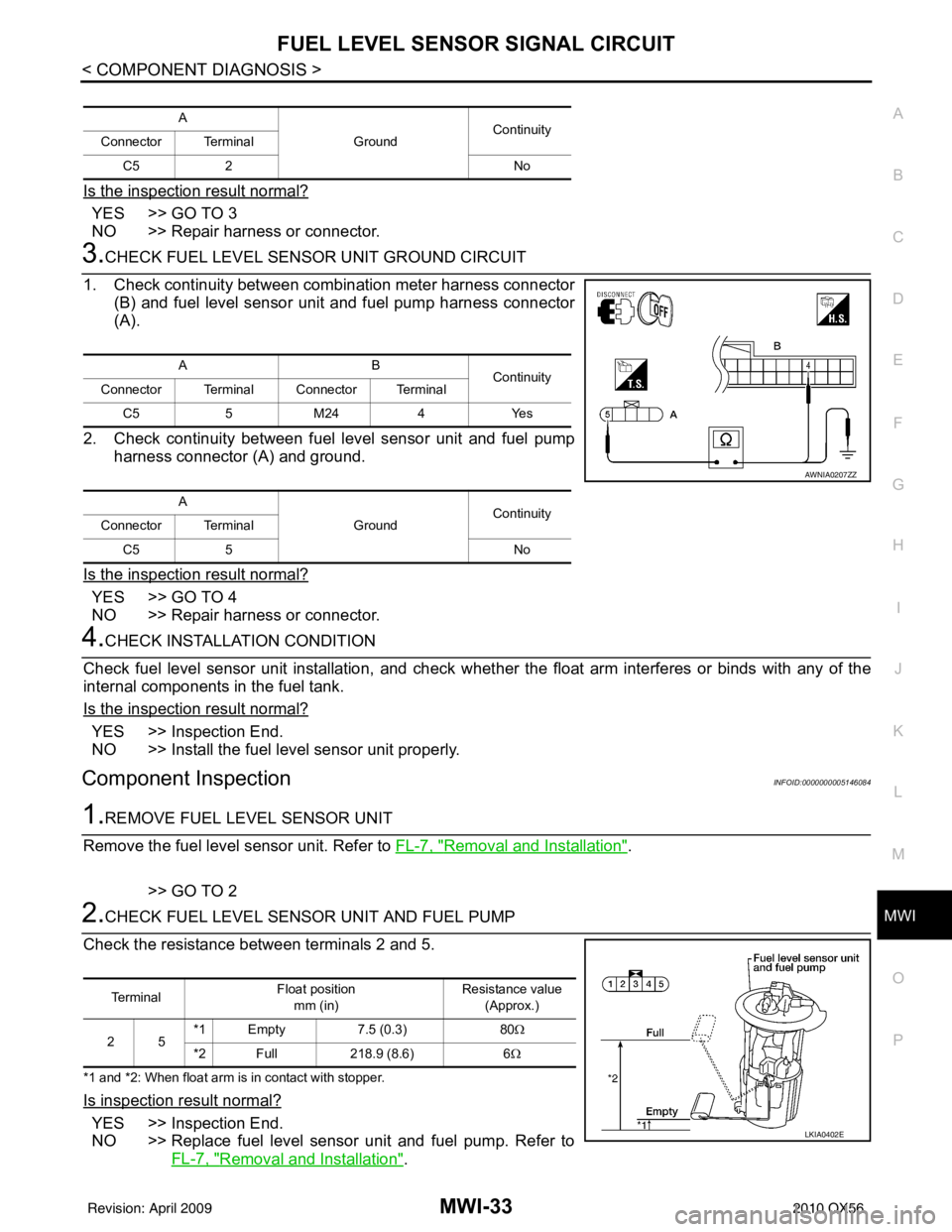
1. Check continuity between combination meter harness connector (B) and fuel level sensor unit and fuel pump harness connector
(A).
2. Check continuity between fuel level sensor unit and fuel pump harness connector (A) and ground.
Is the inspection result normal?
YES >> GO TO 4
NO >> Repair harness or connector.
4.CHECK INSTALLATION CONDITION
Check fuel level sensor unit installation, and check whet her the float arm interferes or binds with any of the
internal components in the fuel tank.
Is the inspection result normal?
YES >> Inspection End.
NO >> Install the fuel level sensor unit properly.
Component InspectionINFOID:0000000005146084
1.REMOVE FUEL LEVEL SENSOR UNIT
Remove the fuel level sensor unit. Refer to FL-7, "
Removal and Installation".
>> GO TO 2
2.CHECK FUEL LEVEL SENSOR UNIT AND FUEL PUMP
Check the resistance between terminals 2 and 5.
*1 and *2: When float arm is in contact with stopper.
Is inspection result normal?
YES >> Inspection End.
NO >> Replace fuel level sensor unit and fuel pump. Refer to FL-7, "
Removal and Installation".
A
GroundContinuity
Connector Terminal
C5 2 No
AB
Continuity
Connector Terminal Connector Terminal
C5 5 M24 4 Yes
A GroundContinuity
Connector Terminal
C5 5 No
AWNIA0207ZZ
Te r m i n a lFloat position
mm (in) Resistance value
(Approx.)
25 *1 Empty 7.5 (0.3) 80
Ω
*2 Full 218.9 (8.6)6Ω
LKIA0402E
Revision: April 20092010 QX56
Page 2801 of 4210
MWI
COMBINATION METERMWI-39
< ECU DIAGNOSIS >
C
DE
F
G H
I
J
K L
M B A
O P
ECU DIAGNOSIS
COMBINATION METER
Reference ValueINFOID:0000000005146098
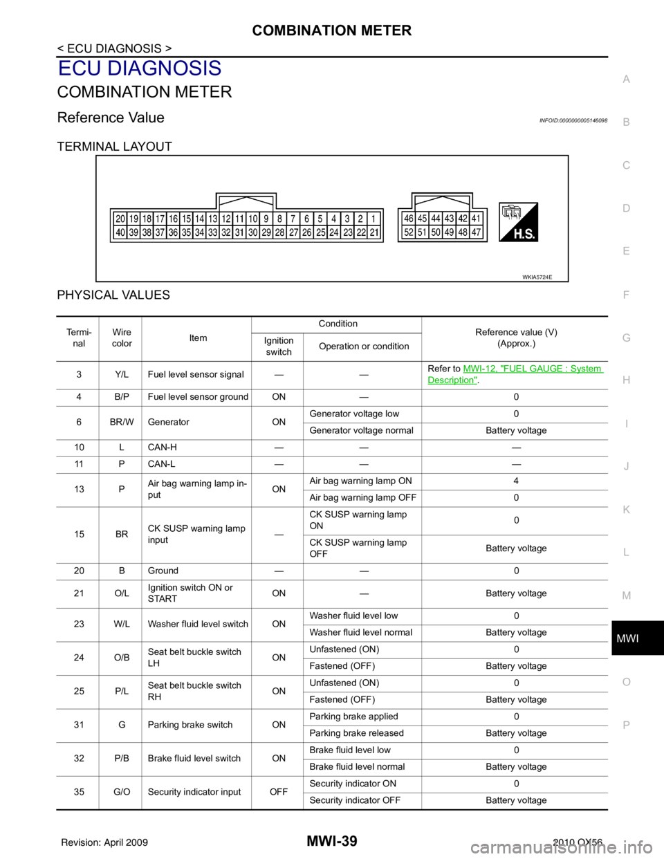
TERMINAL LAYOUT
PHYSICAL VALUES
WKIA5724E
Te r m i - nal Wire
color Item Condition
Reference value (V)
(Approx.)
Ignition
switch Operation or condition
3 Y/L Fuel level sensor signal — —Refer to
MWI-12, "
FUEL GAUGE : System
Description".
4 B/P Fuel level sensor ground ON —0
6 BR/W Generator ONGenerator voltage low
0
Generator voltage normal Battery voltage
10 L CAN-H —— —
11 P C A N - L —— —
13 P Air bag warning lamp in-
put ONAir bag warning lamp ON
4
Air bag warning lamp OFF 0
15 BR CK SUSP warning lamp
input —CK SUSP warning lamp
ON
0
CK SUSP warning lamp
OFF Battery voltage
20 B Ground —— 0
21 O/L Ignition switch ON or
START ON
— Battery voltage
23 W/L Washer fluid level switch ON Washer fluid level low
0
Washer fluid level normal Battery voltage
24 O/B Seat belt buckle switch
LH ONUnfastened (ON)
0
Fastened (OFF) Battery voltage
25 P/L Seat belt buckle switch
RH ONUnfastened (ON)
0
Fastened (OFF) Battery voltage
31 G Parking brake switch ON Parking brake applied
0
Parking brake released Battery voltage
32 P/B Brake fluid level switch ON Brake fluid level low
0
Brake fluid level normal Battery voltage
35 G/O Security indicator input OFF Security indicator ON
0
Security indicator OFF Battery voltage
Revision: April 20092010 QX56
Page 2821 of 4210
MWI
COMBINATION METERMWI-59
< ECU DIAGNOSIS >
C
DE
F
G H
I
J
K L
M B A
O P
DTC IndexINFOID:0000000005146101
NOTE:
Function Specifications
Speedometer
Zero indication.
Tachometer
Fuel gauge
Engine coolant temperature gauge
Engine oil pressure gauge
Voltage gauge
Illumination control
Meter illumination Change to nighttime mode when communication is lost.
Segment LCD Odometer
Freeze current indication.
A/T position Display turns off.
Buzzer Buzzer turns off.
Warning lamp/indicator lamp ABS warning lamp
Lamp turns on when communication is lost.
Brake warning lamp
VDC OFF indicator lamp
SLIP indicator lamp
A/T CHECK warning lamp
Lamp turns off when communication is lost.
Oil pressure/coolant temperature
warning lamp
Light indicator
Malfunction indicator lamp
Master warning lamp
Air bag warning lamp
High beam indicator
Turn signal indicator lamp
CRUISE indicator lamp
Driver and passenger seat belt warn-
ing lamp
Lamp turns off when disconnected.
Charge warning lamp
Security indicator lamp
4WD indicator lamp
ATP indicator lamp
CK SUSP warning lamp
Low tire pressu
re warning lamp Lamp will flash every second for 1 minute and then stay on con-
tinuously thereafter.
CONSULT-III display
MalfunctionReference
page
CAN COMM CIRC
[U1000] Malfunction is detected in CAN communication.
CAUTION:
Even when there is no ma
lfunction on CAN communication system, malfunction may be
misinterpreted when battery has low voltag e (when maintaining 7 - 8 V for about 2 sec-
onds) or 10A fuse [No. 3, located in the fuse block (J/B)] is disconnected. MWI-26
VEHICLE SPEED
CIRC
[B2205]Malfunction is detected when an erroneous speed signal is input.
CAUTION:
Even when there is no malfunction on speed signal system, malfunction may be misin-
terpreted when battery has low voltage (whe
n maintaining 7 - 8 V for about 2 seconds). MWI-27
Revision: April 20092010 QX56
Page 2843 of 4210

MWI
IPDM E/R (INTELLIGENT POWER DISTRIBUTION MODULE ENGINE ROOM)
MWI-81
< ECU DIAGNOSIS >
C
D E
F
G H
I
J
K L
M B A
O P
Te r m i n a l Wire
color Signal name Signal
input/
output Measuring condition
Reference value(Approx.)
Igni-
tion
switch Operation or condition
1 B/Y Battery power supply Input OFF —Battery voltage
2 R Battery power supply Input OFF —Battery voltage
3BRECM relay Output— Ignition switch ON or START
Battery voltage
Ignition switch OFF or ACC 0V
4W/LECM relay Output— Ignition switch ON or START
Battery voltage
Ignition switch OFF or ACC 0V
6L Throttle control motor
relay Output —Ignition switch ON or START
Battery voltage
Ignition switch OFF or ACC 0V
7 W/B ECM relay control Input — Ignition switch ON or START
0V
Ignition switch OFF or ACC Battery voltage
8 R/B Fuse 54 Output —Ignition switch ON or START
Battery voltage
Ignition switch OFF or ACC 0V
10 G Fuse 45
(Canada only) Output ONDaytime light system active
0V
Daytime light system inactive Battery voltage
11 Y/B A/C compressor Output ON or
START A/C switch ON or defrost A/C
switch
Battery voltage
A/C switch OFF or defrost A/C
switch 0V
12 L/W Ignition switch sup-
plied power Input —OFF or ACC
0V
ON or START Battery voltage
13 B/Y Fuel pump relay Output — Ignition switch ON or START
Battery voltage
Ignition switch OFF or ACC 0V
14 Y/R Fuse 49 Output —Ignition switch ON or START
Battery voltage
Ignition switch OFF or ACC 0V
15 LG/B Fuse 50 Output —Ignition switch ON or START
Battery voltage
Ignition switch OFF or ACC 0V
16 G Fuse 51 Output —Ignition switch ON or START
Battery voltage
Ignition switch OFF or ACC 0V
17 W Fuse 55 Output —Ignition switch ON or START
Battery voltage
Ignition switch OFF or ACC 0V
19 W/R Starter motor Output START—Battery voltage
21 BR Ignition switch sup-
plied power
Input —OFF or ACC
0V
START Battery voltage
22 G Battery power supply Output OFF —Battery voltage
23 GR/W Door mirror defogger
output signal Output —When rear defogger switch is
ON
Battery voltage
When raker defogger switch is
OFF 0V
24 L Cooling fan relay Output — Conditions correct for cooling
fan operation
Battery voltage
Conditions not correct for
cooling fan operation 0V
Revision: April 20092010 QX56
Page 2845 of 4210

MWI
IPDM E/R (INTELLIGENT POWER DISTRIBUTION MODULE ENGINE ROOM)
MWI-83
< ECU DIAGNOSIS >
C
D E
F
G H
I
J
K L
M B A
O P
43 L/Y Wiper auto stop signal Input ON or
START Wiper switch OFF, LO, INT Battery voltage
44 BR Daytime light relay
control
(Canada only) Input ONDaytime light system active
0V
Daytime light system inactive Battery voltage
45 G/W Horn relay control Input ON When door locks are operated
using Intelligent Key (OFF
→
ON)* Battery voltage
→ 0V
46 GR Fuel pump relay con-
trol Input —Ignition switch ON or START
0V
Ignition switch OFF or ACC Battery voltage
47 O Throttle control motor
relay control Input —Ignition switch ON or START
0V
Ignition switch OFF or ACC Battery voltage
48 B/R Starter relay (inhibit
switch) Input
ON or
START Selector lever in "P" or "N"
0V
Selector lever any other posi-
tion Battery voltage
49 R/L Trailer tow relay
(With trailer tow)
Illumination
(Without trailer tow) Output ONLighting
switch must
be in the 1st
position OFF
0V
ON Battery voltage
50 W/R Front fog lamp (LH) Output ON or
START Lighting
switch must
be in the 2nd
position
(LOW beam
is ON) and
the front fog
lamp switch OFF
0V
ON Battery voltage
51 W/R Front fog lamp (RH) Output ON or
START Lighting
switch must
be in the 2nd
position
(LOW beam
is ON) and
the front fog
lamp switch OFF
0V
ON Battery voltage
52 L LH low beam head-
lamp
Output — Lighting switch in 2nd position Battery voltage
54 R/Y RH low beam head-
lamp Output — Lighting switch in 2nd position Battery voltage
55 G LH high beam head-
lamp Output —Lighting switch in 2nd position
and placed in HIGH or PASS
position Battery voltage
56 Y
(With
DTRL)
L/W
(Without DTRL) RH high beam head-
lamp
Output —Lighting switch in 2nd position
and placed in HIGH or PASS
position
Battery voltage
57 R/LPa
rking, license, and
tail lamp Output ONLighting
switch 1st po-
sition OFF
0V
ON Battery voltage
59 B Ground Input ——0V
Te r m i n a l
Wire
color Signal name Signal
input/
output Measuring condition
Reference value(Approx.)
Igni-
tion
switch Operation or condition
Revision: April 20092010 QX56
Page 2853 of 4210
MWI
THE FUEL GAUGE POINTER DOES NOT MOVEMWI-91
< SYMPTOM DIAGNOSIS >
C
DE
F
G H
I
J
K L
M B A
O P
SYMPTOM DIAGNOSIS
THE FUEL GAUGE POINTER DOES NOT MOVE
DescriptionINFOID:0000000005146115
Fuel gauge needle will not move from a certain position.
Diagnosis ProcedureINFOID:0000000005146116
1.CHECK COMBINATION METER INPUT SIGNAL
1. Select “METER/M&A” on CONSULT-III.
2. Using “FUEL METER” of “DATA MONITOR”, comp are the monitor value with the fuel gauge reading on
the combination meter. Refer to MWI-32, "
Component Function Check".
Does monitor value match fuel gauge reading?
YES >> GO TO 2
NO >> Replace combination meter. Refer to MWI-100, "
Removal and Installation".
2.CHECK FUEL LEVEL SENSOR SIGNAL CIRCUIT
Check the fuel level sensor signal circuit. Refer to MWI-32, "
DiagnosisProcedure".
Is the inspection result normal?
YES >> GO TO 3
NO >> Repair harness or connector.
3.CHECK FUEL LEVEL SENSOR UNIT
Perform a unit check for the fuel level sensor unit. Refer to MWI-33, "
Component Inspection".
Is the inspection result normal?
YES >> GO TO 4
NO >> Replace fuel level sensor unit. Refer to FL-7, "
Removal and Installation".
4.CHECK FLOAT INTERFERENCE
Check that the float arm does not interfere or bind with any of the components in the fuel tank.
Is the inspection result normal?
YES >> Replace combination meter. Refer to MWI-100, "Removal and Installation".
NO >> Repair or replace malfunctioning parts.
Revision: April 20092010 QX56