2010 INFINITI QX56 fuel
[x] Cancel search: fuelPage 2854 of 4210
MWI-92
< SYMPTOM DIAGNOSIS >
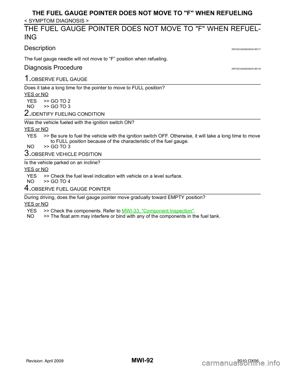
THE FUEL GAUGE POINTER DOES NOT MOVE TO "F" WHEN REFUELING
THE FUEL GAUGE POINTER DOES NO T MOVE TO "F" WHEN REFUEL-
ING
DescriptionINFOID:0000000005146117
The fuel gauge needle will not move to “F” position when refueling.
Diagnosis ProcedureINFOID:0000000005146118
1.OBSERVE FUEL GAUGE
Does it take a long time for the pointer to move to FULL position?
YES or NO
YES >> GO TO 2
NO >> GO TO 3
2.IDENTIFY FUELING CONDITION
Was the vehicle fueled with the ignition switch ON?
YES or NO
YES >> Be sure to fuel the vehicle with the ignition switch OFF. Otherwise, it will take a long time to move to FULL position because of the c haracteristic of the fuel gauge.
NO >> GO TO 3
3.OBSERVE VEHICLE POSITION
Is the vehicle parked on an incline?
YES or NO
YES >> Check the fuel level indication with vehicle on a level surface.
NO >> GO TO 4
4.OBSERVE FUEL GAUGE POINTER
During driving, does the fuel gauge pointer move gradually toward EMPTY position?
YES or NO
YES >> Check the components. Refer to MWI-33, "Component Inspection".
NO >> The float arm may interfere or bind with any of the components in the fuel tank.
Revision: April 20092010 QX56
Page 2881 of 4210
![INFINITI QX56 2010 Factory Service Manual PCS-6
< FUNCTION DIAGNOSIS >[IPDM E/R]
RELAY CONTROL SYSTEM
System Description
INFOID:0000000005146497
IPDM E/R activates the internal cont rol circuit to perform the relay ON-OFF control according to INFINITI QX56 2010 Factory Service Manual PCS-6
< FUNCTION DIAGNOSIS >[IPDM E/R]
RELAY CONTROL SYSTEM
System Description
INFOID:0000000005146497
IPDM E/R activates the internal cont rol circuit to perform the relay ON-OFF control according to](/manual-img/42/57032/w960_57032-2880.png)
PCS-6
< FUNCTION DIAGNOSIS >[IPDM E/R]
RELAY CONTROL SYSTEM
System Description
INFOID:0000000005146497
IPDM E/R activates the internal cont rol circuit to perform the relay ON-OFF control according to the input sig-
nals from various sensors and the request signals received from control units via CAN communication.
CAUTION:
IPDM E/R integrated relays cannot be removed.
Control relay Input/outputTransmit unit Control partReference
page
Front fog lamp relay Front fog lamp request signal BCM (CAN) Front fog lamps EXL-14
• Headlamp LH high relay
• Headlamp RH high relay
• Headlamp low relay• High beam request signal LH
• High beam request signal RH
• Low beam request signal
BCM (CAN)• Headlamp high LH
• Headlamp high RH
• Headlamp low EXL-7
EXL-7
Tail lamp relay
Position light request signal BCM (CAN)•Parking lamps
• License plate lamps
•Tail lamps
• Trailer tow relay
• Illumination system EXL-17
• Front wiper relay
• Front wiper high relay
Front wiper request signal
BCM (CAN) Front wiper motor WW-4
Rear window defogger relay Rear window defogger request signal BCM (CAN) Rear window defogger WW-8
A/C relayA/C request signal •BCM (CAN)
•ECM (CAN)
A/C compressor
HAC-20
Starter relay Ignition switch START signal TCMStarter motor STR-8
Cooling fan relay Cooling fan request signal ECM (CAN) Cooling fan relay EC-36
Heated mirror relayHeated mirror request sign alBCM (CAN) Door mirrors DEF-4
ECM relayECM relay control signal ECM (CAN) ECM relay EC-21
Throttle control motor relay Throttle control moto r control signal ECM (CAN) Throttle control motor re-
layEC-28
Fuel pump relay
Fuel pump request signal ECM (CAN) Fuel pump EC-28
Ignition relayIgnition switch ON signal Ignition switch Ignition relay EC-31
Revision: April 20092010 QX56
Page 2898 of 4210
![INFINITI QX56 2010 Factory Service Manual PCS
IPDM E/R (INTELLIGENT POWER DISTRIBUTION MODULE ENGINE ROOM)
PCS-23
< ECU DIAGNOSIS > [IPDM E/R]
C
D
E
F
G H
I
J
K L
B A
O P
N
Te r m i n a l
Wire
color Signal name Signal
input/
output Measuring INFINITI QX56 2010 Factory Service Manual PCS
IPDM E/R (INTELLIGENT POWER DISTRIBUTION MODULE ENGINE ROOM)
PCS-23
< ECU DIAGNOSIS > [IPDM E/R]
C
D
E
F
G H
I
J
K L
B A
O P
N
Te r m i n a l
Wire
color Signal name Signal
input/
output Measuring](/manual-img/42/57032/w960_57032-2897.png)
PCS
IPDM E/R (INTELLIGENT POWER DISTRIBUTION MODULE ENGINE ROOM)
PCS-23
< ECU DIAGNOSIS > [IPDM E/R]
C
D
E
F
G H
I
J
K L
B A
O P
N
Te r m i n a l
Wire
color Signal name Signal
input/
output Measuring condition
Reference value(Approx.)
Igni-
tion
switch Operation or condition
1 B/Y Battery power supply Input OFF —Battery voltage
2 R Battery power supply Input OFF —Battery voltage
3BRECM relay Output— Ignition switch ON or START
Battery voltage
Ignition switch OFF or ACC 0V
4W/LECM relay Output— Ignition switch ON or START
Battery voltage
Ignition switch OFF or ACC 0V
6L Throttle control motor
relay Output —Ignition switch ON or START
Battery voltage
Ignition switch OFF or ACC 0V
7 W/B ECM relay control Input — Ignition switch ON or START
0V
Ignition switch OFF or ACC Battery voltage
8 R/B Fuse 54 Output —Ignition switch ON or START
Battery voltage
Ignition switch OFF or ACC 0V
10 G Fuse 45
(Canada only) Output ONDaytime light system active
0V
Daytime light system inactive Battery voltage
11 Y/B A/C compressor Output ON or
START A/C switch ON or defrost A/C
switch
Battery voltage
A/C switch OFF or defrost A/C
switch 0V
12 L/W Ignition switch sup-
plied power Input —OFF or ACC
0V
ON or START Battery voltage
13 B/Y Fuel pump relay Output — Ignition switch ON or START
Battery voltage
Ignition switch OFF or ACC 0V
14 Y/R Fuse 49 Output —Ignition switch ON or START
Battery voltage
Ignition switch OFF or ACC 0V
15 LG/B Fuse 50 Output —Ignition switch ON or START
Battery voltage
Ignition switch OFF or ACC 0V
16 G Fuse 51 Output —Ignition switch ON or START
Battery voltage
Ignition switch OFF or ACC 0V
17 W Fuse 55 Output —Ignition switch ON or START
Battery voltage
Ignition switch OFF or ACC 0V
19 W/R Starter motor Output START—Battery voltage
21 BR Ignition switch sup-
plied power
Input —OFF or ACC
0V
START Battery voltage
22 G Battery power supply Output OFF —Battery voltage
23 GR/W Door mirror defogger
output signal Output —When rear defogger switch is
ON
Battery voltage
When raker defogger switch is
OFF 0V
24 L Cooling fan relay Output — Conditions correct for cooling
fan operation
Battery voltage
Conditions not correct for
cooling fan operation 0V
Revision: April 20092010 QX56
Page 2900 of 4210
![INFINITI QX56 2010 Factory Service Manual PCS
IPDM E/R (INTELLIGENT POWER DISTRIBUTION MODULE ENGINE ROOM)
PCS-25
< ECU DIAGNOSIS > [IPDM E/R]
C
D
E
F
G H
I
J
K L
B A
O P
N
43 L/Y Wiper auto stop signal Input
ON or
START Wiper switch OFF, LO INFINITI QX56 2010 Factory Service Manual PCS
IPDM E/R (INTELLIGENT POWER DISTRIBUTION MODULE ENGINE ROOM)
PCS-25
< ECU DIAGNOSIS > [IPDM E/R]
C
D
E
F
G H
I
J
K L
B A
O P
N
43 L/Y Wiper auto stop signal Input
ON or
START Wiper switch OFF, LO](/manual-img/42/57032/w960_57032-2899.png)
PCS
IPDM E/R (INTELLIGENT POWER DISTRIBUTION MODULE ENGINE ROOM)
PCS-25
< ECU DIAGNOSIS > [IPDM E/R]
C
D
E
F
G H
I
J
K L
B A
O P
N
43 L/Y Wiper auto stop signal Input
ON or
START Wiper switch OFF, LO, INT Battery voltage
44 BR Daytime light relay
control
(Canada only) Input ONDaytime light system active
0V
Daytime light system inactive Battery voltage
45 G/W Horn relay control Input ON When door locks are operated
using Intelligent Key (OFF
→
ON)* Battery voltage
→ 0V
46 GR Fuel pump relay con-
trol Input —Ignition switch ON or START
0V
Ignition switch OFF or ACC Battery voltage
47 O Throttle control motor
relay control Input —Ignition switch ON or START
0V
Ignition switch OFF or ACC Battery voltage
48 B/R Starter relay (inhibit
switch) Input
ON or
START Selector lever in "P" or "N"
0V
Selector lever any other posi-
tion Battery voltage
49 R/L Trailer tow relay
(With trailer tow)
Illumination
(Without trailer tow) Output ONLighting
switch must
be in the 1st
position OFF
0V
ON Battery voltage
50 W/R Front fog lamp (LH) Output ON or
START Lighting
switch must
be in the 2nd
position
(LOW beam
is ON) and
the front fog
lamp switch OFF
0V
ON Battery voltage
51 W/R Front fog lamp (RH) Output ON or
START Lighting
switch must
be in the 2nd
position
(LOW beam
is ON) and
the front fog
lamp switch OFF
0V
ON Battery voltage
52 L LH low beam head-
lamp
Output — Lighting switch in 2nd position Battery voltage
54 R/Y RH low beam head-
lamp Output — Lighting switch in 2nd position Battery voltage
55 G LH high beam head-
lamp Output —Lighting switch in 2nd position
and placed in HIGH or PASS
position Battery voltage
56 Y
(With
DTRL)
L/W
(Without DTRL) RH high beam head-
lamp
Output —Lighting switch in 2nd position
and placed in HIGH or PASS
position
Battery voltage
57 R/LPa
rking, license, and
tail lamp Output ONLighting
switch 1st po-
sition OFF
0V
ON Battery voltage
59 B Ground Input ——0V
Te r m i n a l
Wire
color Signal name Signal
input/
output Measuring condition
Reference value(Approx.)
Igni-
tion
switch Operation or condition
Revision: April 20092010 QX56
Page 2959 of 4210
PG
HARNESSPG-49
< COMPONENT DIAGNOSIS >
C
DE
F
G H
I
J
K L
B A
O P
N
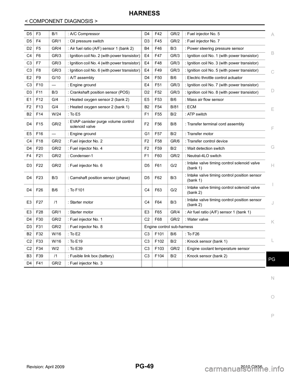
D5 F3 B/1 : A/C Compressor
D4 F42 GR/2 : Fuel injector No. 5
D5 F4 GR/1 : Oil pressure switch D3 F45 GR/2 : Fuel injector No. 7
D2 F5 GR/4 : Air fuel ratio (A/F) sensor 1 (ban k 2) B4 F46 B/3 : Power steering pressure sensor
C4 F6 GR/3 : Ignition coil No. 2 (with power transistor) E4 F47 GR/3 : Ignition coil No. 1 (with power transistor)
C3 F7 GR/3 : Ignition coil No. 4 (with power transistor) E4 F48 GR/3 : Ignition coil No. 3 (with power transistor)
C3 F8 GR/3 : Ignition coil No. 6 (with power transistor) E4 F49 GR/3 : Ignition coil No. 5 (with power transistor)
E2 F9 G/10 : A/T assembly D4 F50 B/6 : Electric throttle control actuator
C3 F10 — : Engine ground E4 F51 GR/3 : Ignition coil No. 7 (with power transistor)
D3 F11 B/3 : Crankshaft position sensor (POS) D2 F52 GR/3 : Ignition coil No. 8 (with power transistor)
E1 F12 G/4 : Heated oxygen sensor 2 (bank 2) E5 F53 B/6 : Mass air flow sensor
F2 F13 G/4 : Heated oxygen sensor 2 (bank 1) B2 F54 B/81 : ECM
B2 F14 W/24 : To E5 F1 F55 B/2 : ATP switch
D4 F15 GR/2 : EVAP canister purge volume control
solenoid valve F2 F56 B/8 : Transfer terminal cord assembly
E5 F16 — : Engine ground G1 F57 B/2 : Transfer motor
C4 F18 GR/2 : Fuel injector No. 2 F2 F58 GR/6 : Transfer control device
D4 F20 GR/2 : Fuel injector No. 4 F2 F59 B/2 : Wait detection switch
F4 F21 GR/2 : Condenser-1 F1 F60 GR/2 : Neutral-4LO switch
D3 F22 GR/2 : Fuel inje ctor No. 6 D5 F61 G/2: Intake valve timing control solenoid valve
(bank 1)
D4 F23 B/3 : Camshaft position sensor (phase) D5 F62 B/3 : Intake valve timing control position sensor
(bank 1)
D4 F26 B/6 : To F101 C4 F63 G/2: Intake valve timing control solenoid valve
(bank 2)
E3 F27 /1 : Starter motor C4 F64 B/3: Intake valve timing control position sensor
(bank 2)
E3 F28 GR/1 : Starter motor E3 F65 GR/4 : Air fuel ratio (A/F) sensor 1 (bank 1)
D4 F30 GR/2 : Fuel injector No. 1 C2 F68 GR/2 : Water valve
D3 F31 GR/2 : Fuel injector No. 8 Engine control sub-harness
B2 F32 W/16 : To E2 C3 F101 B/6 : To F26
C2 F33 W/16 : To E19 C3 F102 B/2 : Knock sensor (bank 1)
C2 F34 W/2 : To E39 C3 F103 GR/2 : Engine coolant temperature sensor
B3 F39 /1 : Fusible link box (battery) C3 F104 B/2 : Knock sensor (bank 2)
D4 F41 GR/2 : Fuel injector No. 3
Revision: April 20092010 QX56
Page 2960 of 4210
PG-50
< COMPONENT DIAGNOSIS >
HARNESS
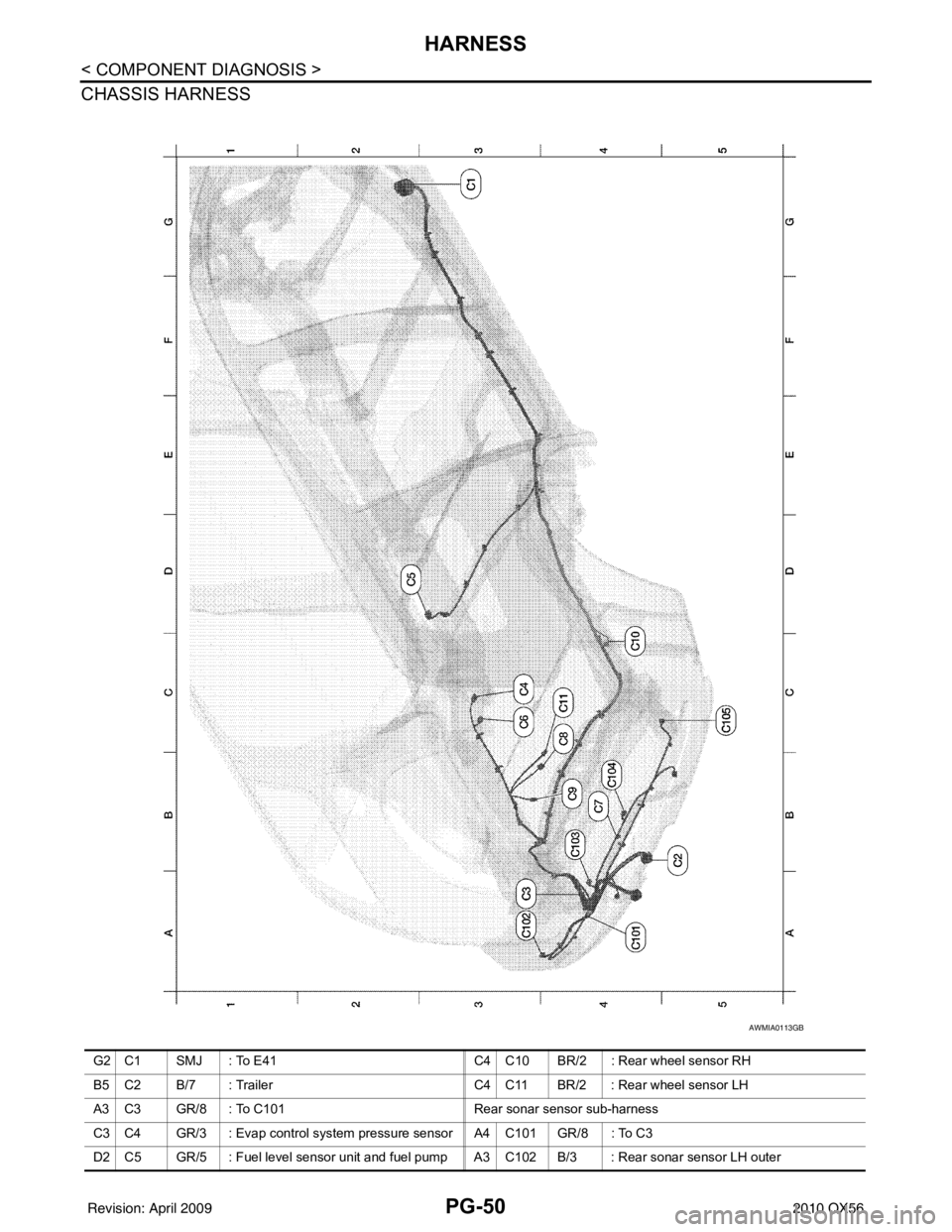
CHASSIS HARNESS
AWMIA0113GB
G2 C1 SMJ : To E41C4 C10 BR/2 : Rear wheel sensor RH
B5 C2 B/7 : Trailer C4 C11 BR/2 : Rear wheel sensor LH
A3 C3 GR/8 : To C101 Rear sonar sensor sub-harness
C3 C4 GR/3 : Evap control system pressure sensor A4 C101 GR/8 : To C3
D2 C5 GR/5 : Fuel level sensor unit and fuel pump A3 C102 B/3 : Rear sonar sensor LH outer
Revision: April 20092010 QX56
Page 3190 of 4210
PRECAUTIONSRSU-3
< PRECAUTION >
C
DF
G H
I
J
K L
M A
B
RSU
N
O P
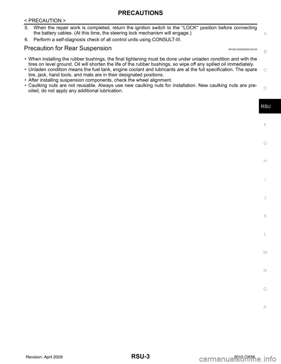
5. When the repair work is completed, return the ignition switch to the ″LOCK ″ position before connecting
the battery cables. (At this time, the steering lock mechanism will engage.)
6. Perform a self-diagnosis check of al l control units using CONSULT-III.
Precaution for Rear SuspensionINFOID:0000000005148126
• When installing the rubber bushings, the final tightening must be done under unladen condition and with the
tires on level ground. Oil will shorten the life of the rubber bushings, so wipe off any spilled oil immediately.
• Unladen condition means the fuel tank, engine coolant and lubricants are at the full specification. The spare
tire, jack, hand tools, and mats are in their designated positions.
• After installing suspension components, check the wheel alignment.
• Caulking nuts are not reusable. Always use new caulking nuts for installation. New caulking nuts are pre- oiled, do not apply any additional lubrication.
Revision: April 20092010 QX56
Page 3193 of 4210
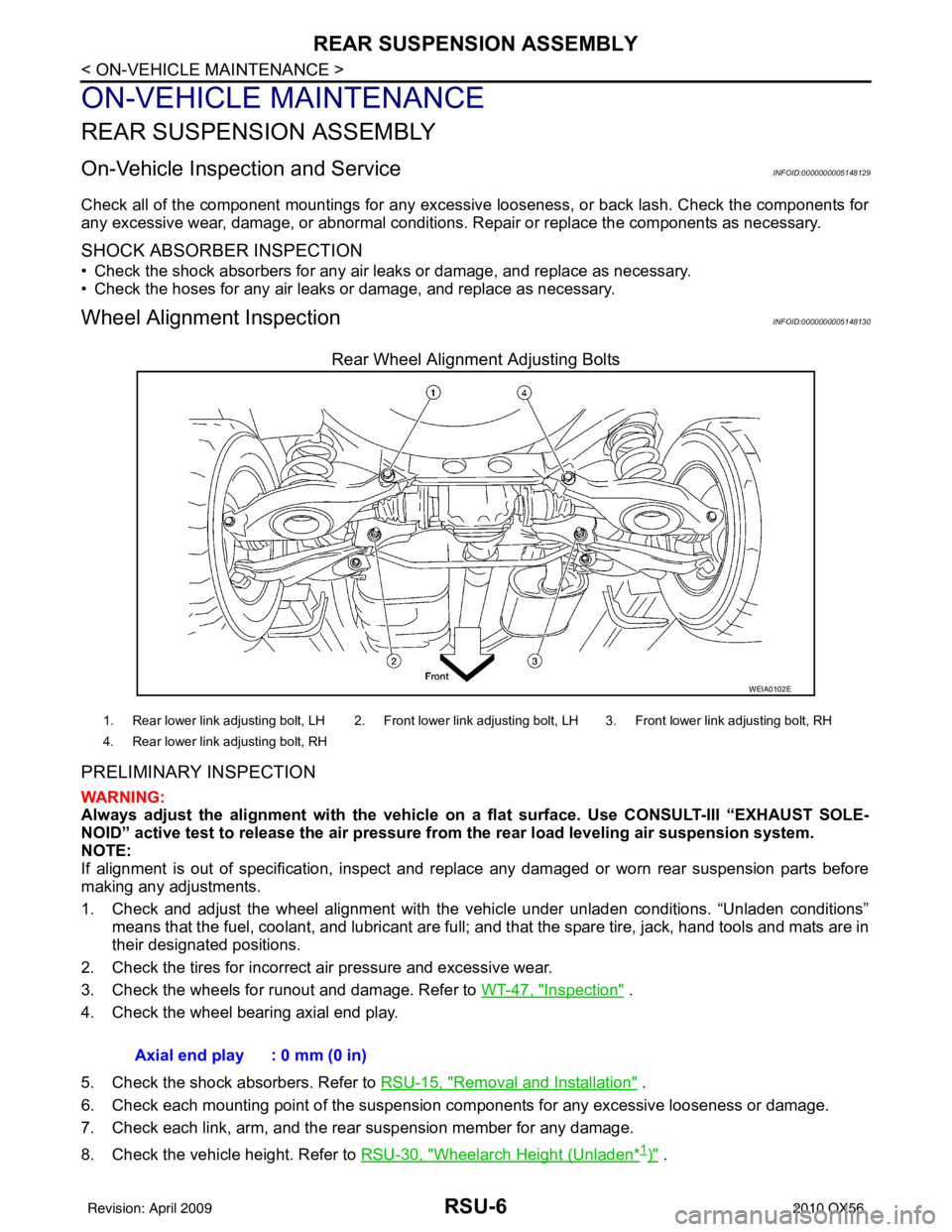
RSU-6
< ON-VEHICLE MAINTENANCE >
REAR SUSPENSION ASSEMBLY
ON-VEHICLE MAINTENANCE
REAR SUSPENSION ASSEMBLY
On-Vehicle Inspection and ServiceINFOID:0000000005148129
Check all of the component mountings for any excessive looseness, or back lash. Check the components for
any excessive wear, damage, or abnormal conditions. Repair or replace the components as necessary.
SHOCK ABSORBER INSPECTION
• Check the shock absorbers for any air leaks or damage, and replace as necessary.
• Check the hoses for any air leaks or damage, and replace as necessary.
Wheel Alignment InspectionINFOID:0000000005148130
Rear Wheel Alignment Adjusting Bolts
PRELIMINARY INSPECTION
WARNING:
Always adjust the alignment with the vehicle on a flat surface. Use CONSULT-III “EXHAUST SOLE-
NOID” active test to release the air pressure from the rear load leveling air suspension system.
NOTE:
If alignment is out of specificat ion, inspect and replace any damaged or worn rear suspension parts before
making any adjustments.
1. Check and adjust the wheel alignment with the vehicle under unladen conditions. “Unladen conditions”
means that the fuel, coolant, and lubricant are full; and that the spare tire, jack, hand tools and mats are in
their designated positions.
2. Check the tires for incorrect air pressure and excessive wear.
3. Check the wheels for runout and damage. Refer to WT-47, "
Inspection" .
4. Check the wheel bearing axial end play.
5. Check the shock absorbers. Refer to RSU-15, "
Removal and Installation" .
6. Check each mounting point of the suspension components for any excessive looseness or damage.
7. Check each link, arm, and the rear suspension member for any damage.
8. Check the vehicle height. Refer to RSU-30, "
Wheelarch Height (Unladen*1)" .
WEIA0102E
1. Rear lower link adjusting bolt, LH 2. Front lower link adjusting bolt, LH 3. Front lower link adjusting bolt, RH
4. Rear lower link adjusting bolt, RH
Axial end play : 0 mm (0 in)
Revision: April 20092010 QX56