Page 2081 of 4210
TRAILER TOWEXL-105
< COMPONENT DIAGNOSIS >
C
DE
F
G H
I
J
K
M A
B
EXL
N
O P
ABLIA1455GB
Revision: April 20092010 QX56
Page 2103 of 4210

IPDM E/R (INTELLIGENT POWER DISTRIBUTION MODULE ENGINE ROOM)
EXL-127
< ECU DIAGNOSIS >
C
D E
F
G H
I
J
K
M A
B
EXL
N
O P
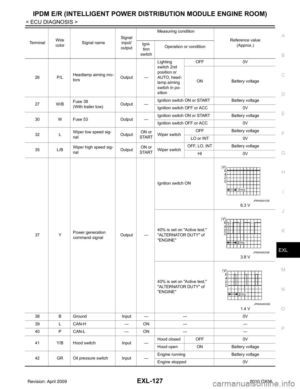
26 P/L Headlamp aiming mo-
tors
Output —Lighting
switch 2nd
position or
AUTO, head-
lamp aiming
switch in po-
sition OFF
0V
ON Battery voltage
27 W/B Fuse 38
(With trailer tow)
Output —Ignition switch ON or START
Battery voltage
Ignition switch OFF or ACC 0V
30 W Fuse 53 Output —Ignition switch ON or START
Battery voltage
Ignition switch OFF or ACC 0V
32 L Wiper low speed sig-
nal
OutputON or
START Wiper switch OFF
Battery voltage
LO or INT 0V
35 L/B Wiper high speed sig-
nal
OutputON or
START Wiper switch OFF, LO, INT Battery voltage
HI 0V
37 Y Power generation
command signal Output —Ignition switch ON
6.3 V
40% is set on "Active test,"
"ALTERNATOR DUTY" of
"ENGINE" 3.8 V
40% is set on "Active test,"
"ALTERNATOR DUTY" of
"ENGINE" 1.4 V
38 B Ground Input ——0V
39 L CAN-H — ON— —
40 P CAN-L — ON— —
41 Y/B Hood switch Input —Hood closed OFF
0V
Hood open ON Battery voltage
42 GR Oil pressure switch Input — Engine running
Battery voltage
Engine stopped 0V
Te r m i n a l
Wire
color Signal name Signal
input/
output Measuring condition
Reference value(Approx.)
Igni-
tion
switch Operation or condition
JPMIA0001GB
JPMIA0002GB
JPMIA0003GB
Revision: April 20092010 QX56
Page 2104 of 4210

EXL-128
< ECU DIAGNOSIS >
IPDM E/R (INTELLIGENT POWER DISTRIBUTION MODULE ENGINE ROOM)
43 L/Y Wiper auto stop signal Input ON or
START Wiper switch OFF, LO, INT Battery voltage
44 BR Daytime light relay
control
(Canada only) Input ONDaytime light system active
0V
Daytime light system inactive Battery voltage
45 G/W Horn relay control Input ON When door locks are operated
using Intelligent Key (OFF
→
ON)* Battery voltage
→ 0V
46 GR Fuel pump relay con-
trol Input —Ignition switch ON or START
0V
Ignition switch OFF or ACC Battery voltage
47 O Throttle control motor
relay control Input —Ignition switch ON or START
0V
Ignition switch OFF or ACC Battery voltage
48 B/R Starter relay (inhibit
switch) Input
ON or
START Selector lever in "P" or "N"
0V
Selector lever any other posi-
tion Battery voltage
49 R/L Trailer tow relay
(With trailer tow)
Illumination
(Without trailer tow) Output ONLighting
switch must
be in the 1st
position OFF
0V
ON Battery voltage
50 W/R Front fog lamp (LH) Output ON or
START Lighting
switch must
be in the 2nd
position
(LOW beam
is ON) and
the front fog
lamp switch OFF
0V
ON Battery voltage
51 W/R Front fog lamp (RH) Output ON or
START Lighting
switch must
be in the 2nd
position
(LOW beam
is ON) and
the front fog
lamp switch OFF
0V
ON Battery voltage
52 L LH low beam head-
lamp
Output — Lighting switch in 2nd position Battery voltage
54 R/Y RH low beam head-
lamp Output — Lighting switch in 2nd position Battery voltage
55 G LH high beam head-
lamp Output —Lighting switch in 2nd position
and placed in HIGH or PASS
position Battery voltage
56 Y
(With
DTRL)
L/W
(Without DTRL) RH high beam head-
lamp
Output —Lighting switch in 2nd position
and placed in HIGH or PASS
position
Battery voltage
57 R/LPa
rking, license, and
tail lamp Output ONLighting
switch 1st po-
sition OFF
0V
ON Battery voltage
59 B Ground Input ——0V
Te r m i n a l
Wire
color Signal name Signal
input/
output Measuring condition
Reference value(Approx.)
Igni-
tion
switch Operation or condition
Revision: April 20092010 QX56
Page 2105 of 4210
IPDM E/R (INTELLIGENT POWER DISTRIBUTION MODULE ENGINE ROOM)
EXL-129
< ECU DIAGNOSIS >
C
D E
F
G H
I
J
K
M A
B
EXL
N
O P
*: When horn reminder is ON 60 B/W
Rear window defog-
ger relay
OutputON or
START Rear defogger switch ON
Battery voltage
Rear defogger switch OFF 0V
61 BR Fuse 32
(With trailer tow) Output OFF
—Battery voltage
Te r m i n a l
Wire
color Signal name Signal
input/
output Measuring condition
Reference value(Approx.)
Igni-
tion
switch Operation or condition
Revision: April 20092010 QX56
Page 2121 of 4210
ADJUSTMENT AND INSPECTIONEXL-145
< ON-VEHICLE REPAIR >
C
DE
F
G H
I
J
K
M A
B
EXL
N
O P
ON-VEHICLE REPAIR
ADJUSTMENT AND INSPECTION
HEADLAMP
HEADLAMP : Aiming AdjustmentINFOID:0000000005146696
NOTE:
• For details, refer to the regulations in your area.
• If vehicle front body has been repaired and /or the headlamp assembly has been replaced, check headlamp
aiming.
HEADLAMP AIMING
NOTE:
• Before performing aiming adjustment, check the following:
- Ensure all tires are inflated to correct pressure.
- Place vehicle and screen on level surface.
- Ensure there is no load in vehicle other than the driver (or equivalent weight placed in driver's position). Coolant and engine oil filled to correct level, and fuel tank full.
- Confirm spare tire, jack and tools are properly stowed.
- Aim each headlamp individually and ensure other headlamp beam pattern is blocked from screen.
- Use adjusting screw to perform aiming adjustment
WKIA1859E
Revision: April 20092010 QX56
Page 2130 of 4210
EXL-154
< REMOVAL AND INSTALLATION >
LIGHTING & TURN SIGNAL SWITCH
LIGHTING & TURN SIGNAL SWITCH
Removal and InstallationINFOID:0000000005146704
REMOVAL
1. Remove steering column cover.
2. While pressing tabs, pull lighting and turn signal switch toward
driver door and disconnect from the base.
INSTALLATION
Installation is in the reverse order of removal.
LKIA0013E
Revision: April 20092010 QX56
Page 2151 of 4210

EXT-16
< SERVICE INFORMATION >
REAR BUMPER
REMOVAL
1. Remove the rear combination lamps LH and RH. Refer to EXL-158, "Removal and Installation".
2. Remove the rear fascia assembly screws under the rear combination lamps LH and RH.
3. Remove the quarter panel trim covers LH and RH.
4. Disconnect the sonar sensor harness c onnector under the rear fascia assembly.
5. Release the retainer clips on both sides of the rear fascia assembly with a 1/4 turn and top S clips and remove the fascia assembly.
6. Detach the I-key antenna from the energy absorber.
7. Remove the energy absorber.
8. Remove the reinforcement assembly.
9. Remove the nuts and remove the retainer assembly. • Remove the S clips from the retainer assembly.
10. Disconnect the sonar sensors from the sonar sensor retainers.
11. Remove the sonar sensors and harness from the rear fascia assembly. • Disconnect the sonar sensors from the harness.
• Remove the sonar sensor retainers from the rear fascia assembly.
12. Remove the bolts on each side of the tow hitch and remove the tow hitch.
13. Remove the drafter duct from under the LH quarter pane, if necessary.
INSTALLATION
Installation is in the reverse order of removal.
10. Rear fascia assembly 11. Sonar sensor retainer12. Reinforcement assembly
13. Tow hitch 14. Quarter panel trim cover RH
Revision: April 20092010 QX56
Page 2178 of 4210

FAX-12
< DISASSEMBLY AND ASSEMBLY >
DRIVE SHAFT
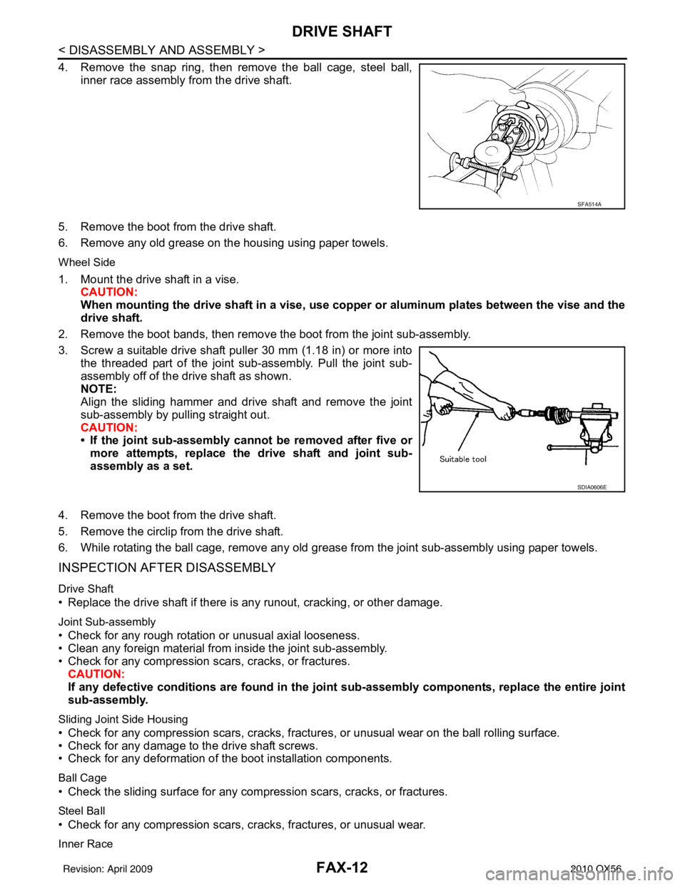
4. Remove the snap ring, then remove the ball cage, steel ball,inner race assembly from the drive shaft.
5. Remove the boot from the drive shaft.
6. Remove any old grease on the housing using paper towels.
Wheel Side
1. Mount the drive shaft in a vise. CAUTION:
When mounting the drive shaft in a vise, use copp er or aluminum plates between the vise and the
drive shaft.
2. Remove the boot bands, then remove the boot from the joint sub-assembly.
3. Screw a suitable drive shaft puller 30 mm (1.18 in) or more into the threaded part of the joint sub-assembly. Pull the joint sub-
assembly off of the drive shaft as shown.
NOTE:
Align the sliding hammer and drive shaft and remove the joint
sub-assembly by pulling straight out.
CAUTION:
• If the joint sub-assembly cannot be removed after five ormore attempts, replace the drive shaft and joint sub-
assembly as a set.
4. Remove the boot from the drive shaft.
5. Remove the circlip from the drive shaft.
6. While rotating the ball cage, remove any old grease from the joint sub-assembly using paper towels.
INSPECTION AFTER DISASSEMBLY
Drive Shaft
• Replace the drive shaft if there is any runout, cracking, or other damage.
Joint Sub-assembly
• Check for any rough rotation or unusual axial looseness.
• Clean any foreign material from inside the joint sub-assembly.
• Check for any compression scars, cracks, or fractures.
CAUTION:
If any defective conditions are found in the joint sub-assembly comp onents, replace the entire joint
sub-assembly.
Sliding Joint Side Housing
• Check for any compression scars, cracks, fracture s, or unusual wear on the ball rolling surface.
• Check for any damage to the drive shaft screws.
• Check for any deformation of the boot installation components.
Ball Cage
• Check the sliding surface for any compression scars, cracks, or fractures.
Steel Ball
• Check for any compression scars, cr acks, fractures, or unusual wear.
Inner Race
SFA514A
SDIA0606E
Revision: April 20092010 QX56