2010 INFINITI QX56 ad blue
[x] Cancel search: ad bluePage 1283 of 4210
![INFINITI QX56 2010 Factory Service Manual SERVICE DATA AND SPECIFICATIONS (SDS)DLN-201
< SERVICE DATA AND SPECIFICATIONS (SDS) [PROPELLER SHAFT: 2S1410]
C
EF
G H
I
J
K L
M A
B
DLN
N
O P
SERVICE DATA AND SPECIFICATIONS (SDS)
SERVICE DATA AND INFINITI QX56 2010 Factory Service Manual SERVICE DATA AND SPECIFICATIONS (SDS)DLN-201
< SERVICE DATA AND SPECIFICATIONS (SDS) [PROPELLER SHAFT: 2S1410]
C
EF
G H
I
J
K L
M A
B
DLN
N
O P
SERVICE DATA AND SPECIFICATIONS (SDS)
SERVICE DATA AND](/manual-img/42/57032/w960_57032-1282.png)
SERVICE DATA AND SPECIFICATIONS (SDS)DLN-201
< SERVICE DATA AND SPECIFICATIONS (SDS) [PROPELLER SHAFT: 2S1410]
C
EF
G H
I
J
K L
M A
B
DLN
N
O P
SERVICE DATA AND SPECIFICATIONS (SDS)
SERVICE DATA AND SPECIFICATIONS (SDS)
General SpecificationINFOID:0000000005148910
Propeller Shaft Runout
Unit: mm (in)
Propeller Shaft Joint Flex Effort
Unit: N·m (kg-m, in-lb)
Journal Axial Play
Unit: mm (in)
Snap RingINFOID:0000000005148911
Model (2WD) Unit: mm (in)
*Always check with the Parts Department for the latest parts information.
Model (4WD)
Unit: mm (in)
Applied model2WD
4WD
VK56DE A/T
Propeller shaft model 2S1410
Number of joints 2
Coupling method with rear final drive Flange type
Coupling method with transfer Sleeve type
Shaft length (Spider to spider) 1637.1 (44.35)1156.8 (45.54)
Shaft outer diameter 127.60 (5.02)102.46 (4.03)
Item Limit
Propeller shaft runout 1.02 (0.0402) or less
ItemLimit
Propeller shaft joint flex effort 2.26 (0.23, 20) or less
ItemLimit
Journal axial play 0.02 (0.0008) or less
ThicknessColorPart Number*
1.600 - 1.638 (0.0630 - 0.0645) Black37146-EA500
1.549 - 1.588 (0.0610 - 0.0625) Black37147-EA500
1.524 - 1.562 (0.0600 - 0.0615) Black37148-EA500
1.499 - 1.537 (0.0590 - 0.0605) Black37149-EA500
Thickness ColorPart Number*
1.99 (0.0783) White37146-C9400
2.02 (0.0795) Yellow37147-C9400
2.05 (0.0807) Red37148-C9400
2.08 (0.0819) Green37149-C9400
2.11 (0.0831) Blue37150-C9400
Revision: April 20092010 QX56
Page 1891 of 4210
EM-40
< ON-VEHICLE REPAIR >
FUEL INJECTOR AND FUEL TUBE
FUEL INJECTOR AND FUEL TUBE
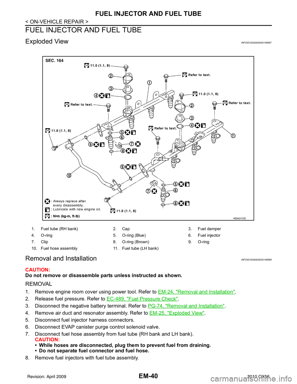
Exploded ViewINFOID:0000000005148997
Removal and InstallationINFOID:0000000005148998
CAUTION:
Do not remove or disassemble parts unless instructed as shown.
REMOVAL
1. Remove engine room cover using power tool. Refer to EM-24, "Removal and Installation".
2. Release fuel pressure. Refer to EC-489, "
Fuel Pressure Check".
3. Disconnect the negative battery terminal. Refer to PG-74, "
Removal and Installation".
4. Remove air duct and resonator assembly. Refer to EM-25, "
Exploded View".
5. Disconnect fuel injector harness connectors.
6. Disconnect EVAP canister purge control solenoid valve.
7. Disconnect fuel hose assembly from fuel tube (RH bank and LH bank). CAUTION:
• While hoses are disconnected, plug th em to prevent fuel from draining.
• Do not separate fuel co nnector and fuel hose.
8. Remove fuel injectors with fuel tube assembly.
1. Fuel tube (RH bank) 2. Cap3. Fuel damper
4. O-ring 5. O-ring (Blue)6. Fuel injector
7. Clip 8. O-ring (Brown)9. O-ring
10. Fuel hose assembly 11. Fuel tube (LH bank)
KBIA2472E
Revision: April 20092010 QX56
Page 1892 of 4210

FUEL INJECTOR AND FUEL TUBEEM-41
< ON-VEHICLE REPAIR >
C
DE
F
G H
I
J
K L
M A
EM
NP
O
9. Remove fuel injector from fuel tube.
a. Spread open to remove clip.
b. Remove fuel injector from the
fuel tube by pulling straight out.
CAUTION:
• Be careful with remaining fuel that may leak out from fuel
tube.
• Do not damage injector nozzles during removal.
• Do not bump or drop fuel injectors.
• Do not disassemble fuel injectors.
10. Remove fuel damper from each fuel tube.
INSTALLATION
1. Install fuel damper to each fuel tube.
a. Apply engine oil to O-ring and set it into the cap of fuel tube. CAUTION:
• Handle O-ring with bare hands. Never wear gloves.
• Lubricate O-ring with new engine oil.
• Do not clean O-ring with solvent.
• Make sure that O-ring and its mating part are free of for- eign material.
• When installing O-ring, be car eful not to scratch it with
tool or fingernails. Also be careful not to twist or stretch
O-ring.
b. Make sure that backup spacer is in the O-ring connecting sur- face of fuel damper.
NOTE:
Backup spacer is fuel damper assembly part.
c. Insert fuel damper until it seats on fuel tube. CAUTION:
• Insert straight, making sure that the axis is lined up.
• Do not pressure-fit with excessive force.
d. Install cap, and then tighten bolts evenly by turns. • After tightening bolts, make sure that there is no gap between cap and fuel tube.
2. Install O-rings to fuel injector paying attention to the items below. CAUTION:
• Upper and lower O-ring are different.
• Handle O-ring with bare hands. Never wear gloves.
KBIA2506E
Reference value :130 N (13.3 kg, 29.2 lb)
Fuel tube side : Blue
Nozzle side : Brown
KBIA2473E
Revision: April 20092010 QX56
Page 1926 of 4210
CYLINDER HEADEM-75
< ON-VEHICLE REPAIR >
C
DE
F
G H
I
J
K L
M A
EM
NP
O
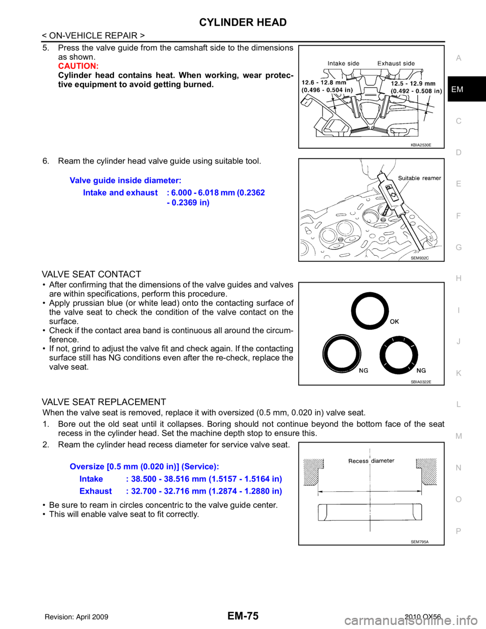
5. Press the valve guide from the camshaft side to the dimensions
as shown.
CAUTION:
Cylinder head contains heat . When working, wear protec-
tive equipment to avo id getting burned.
6. Ream the cylinder head valve guide using suitable tool.
VALVE SEAT CONTACT
• After confirming that the dimensions of the valve guides and valves are within specifications, perform this procedure.
• Apply prussian blue (or white lead) onto the contacting surface of the valve seat to check the condition of the valve contact on the
surface.
• Check if the contact area band is continuous all around the circum- ference.
• If not, grind to adjust the valve fi t and check again. If the contacting
surface still has NG conditions even after the re-check, replace the
valve seat.
VALVE SEAT REPLACEMENT
When the valve seat is removed, replace it with oversized (0.5 mm, 0.020 in) valve seat.
1. Bore out the old seat until it collapses. Boring should not continue beyond the bottom face of the seat recess in the cylinder head. Set the machine depth stop to ensure this.
2. Ream the cylinder head recess diameter for service valve seat.
• Be sure to ream in circles concentric to the valve guide center.
• This will enable valve seat to fit correctly.
KBIA2530E
Valve guide inside diameter:
Intake and exhaust : 6.000 - 6.018 mm (0.2362 - 0.2369 in)
SEM932C
SBIA0322E
Oversize [0.5 mm (0.020 in)] (Service):
Intake : 38.500 - 38.516 mm (1.5157 - 1.5164 in)
Exhaust : 32.700 - 32.716 mm (1.2874 - 1.2880 in)
SEM795A
Revision: April 20092010 QX56
Page 1957 of 4210
EM-106
< DISASSEMBLY AND ASSEMBLY >
HOW TO SELECT PISTON AND BEARING
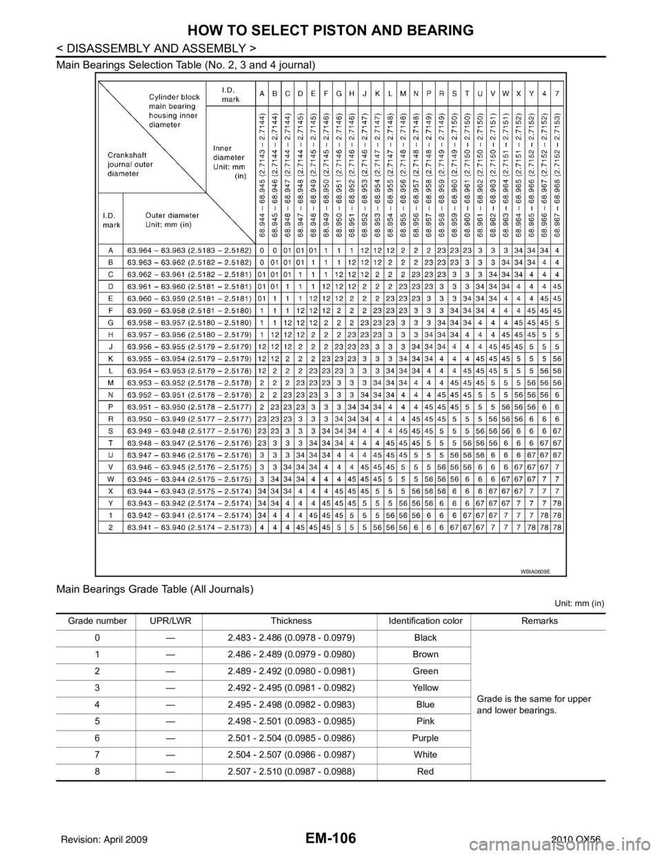
Main Bearings Selection Table (No. 2, 3 and 4 journal)
Main Bearings Grade Table (All Journals)
Unit: mm (in)
WBIA0609E
Grade number UPR/LWRThickness Identification color Remarks
0 —2.483 - 2.486 (0.0978 - 0.0979) Black
Grade is the same for upper
and lower bearings.
1
—2.486 - 2.489 (0.0979 - 0.0980) Brown
2 —2.489 - 2.492 (0.0980 - 0.0981) Green
3 —2.492 - 2.495 (0.0981 - 0.0982) Yellow
4 —2.495 - 2.498 (0.0982 - 0.0983) Blue
5 —2.498 - 2.501 (0.0983 - 0.0985) Pink
6 —2.501 - 2.504 (0.0985 - 0.0986) Purple
7 —2.504 - 2.507 (0.0986 - 0.0987) White
8 —2.507 - 2.510 (0.0987 - 0.0988) Red
Revision: April 20092010 QX56
Page 1958 of 4210
HOW TO SELECT PISTON AND BEARINGEM-107
< DISASSEMBLY AND ASSEMBLY >
C
DE
F
G H
I
J
K L
M A
EM
NP
O
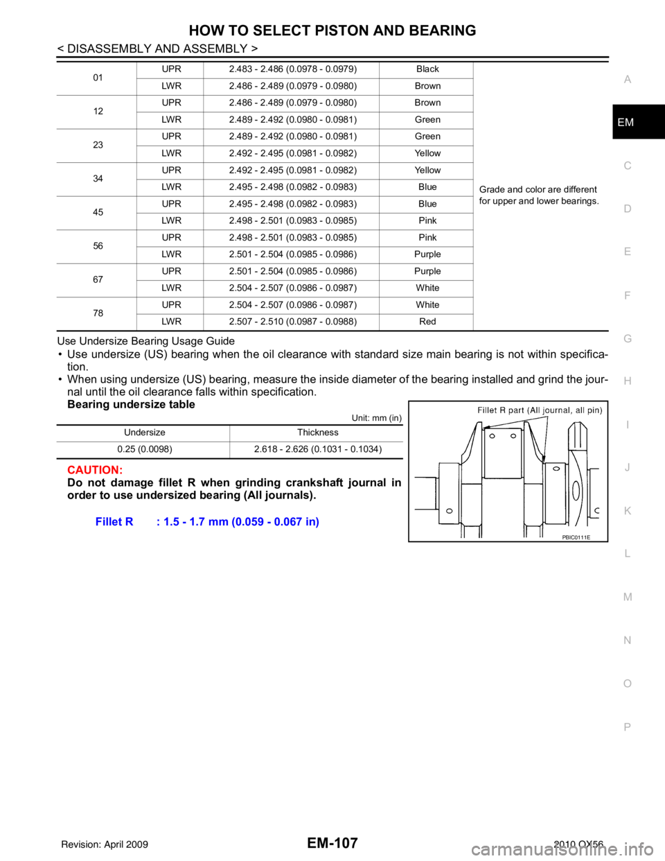
Use Undersize Bearing Usage Guide
• Use undersize (US) bearing when the oil clearance with
standard size main bearing is not within specifica-
tion.
• When using undersize (US) bearing, measure the inside di ameter of the bearing installed and grind the jour-
nal until the oil clearance falls within specification.
Bearing undersize table
Unit: mm (in)
CAUTION:
Do not damage fillet R when grinding crankshaft journal in
order to use undersized bearing (All journals).
01 UPR
2.483 - 2.486 (0.0978 - 0.0979) Black
Grade and color are different
for upper and lower bearings.
LWR
2.486 - 2.489 (0.0979 - 0.0980) Brown
12 UPR
2.486 - 2.489 (0.0979 - 0.0980) Brown
LWR 2.489 - 2.492 (0.0980 - 0.0981) Green
23 UPR
2.489 - 2.492 (0.0980 - 0.0981) Green
LWR 2.492 - 2.495 (0.0981 - 0.0982) Yellow
34 UPR
2.492 - 2.495 (0.0981 - 0.0982) Yellow
LWR 2.495 - 2.498 (0.0982 - 0.0983) Blue
45 UPR
2.495 - 2.498 (0.0982 - 0.0983) Blue
LWR 2.498 - 2.501 (0.0983 - 0.0985) Pink
56 UPR
2.498 - 2.501 (0.0983 - 0.0985) Pink
LWR 2.501 - 2.504 (0.0985 - 0.0986) Purple
67 UPR
2.501 - 2.504 (0.0985 - 0.0986) Purple
LWR 2.504 - 2.507 (0.0986 - 0.0987) White
78 UPR
2.504 - 2.507 (0.0986 - 0.0987) White
LWR 2.507 - 2.510 (0.0987 - 0.0988) Red
UndersizeThickness
0.25 (0.0098) 2.618 - 2.626 (0.1031 - 0.1034)
Fillet R : 1.5 - 1.7 mm (0.059 - 0.067 in)
PBIC0111E
Revision: April 20092010 QX56
Page 1968 of 4210
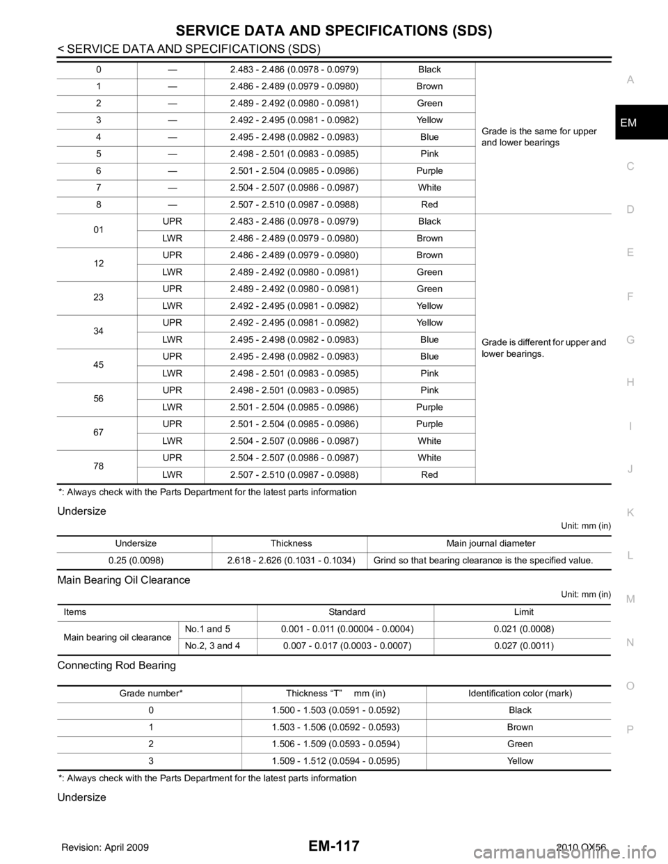
SERVICE DATA AND SPECIFICATIONS (SDS)EM-117
< SERVICE DATA AND SPECIFICATIONS (SDS)
C
DE
F
G H
I
J
K L
M A
EM
NP
O
*: Always check with the Parts Department for the latest parts information
Undersize
Unit: mm (in)
Main Bearing Oil Clearance
Unit: mm (in)
Connecting Rod Bearing
*: Always check with the Parts Department for the latest parts information
Undersize
0
—2.483 - 2.486 (0.0978 - 0.0979) Black
Grade is the same for upper
and lower bearings
1
—2.486 - 2.489 (0.0979 - 0.0980) Brown
2 —2.489 - 2.492 (0.0980 - 0.0981) Green
3 —2.492 - 2.495 (0.0981 - 0.0982) Yellow
4 —2.495 - 2.498 (0.0982 - 0.0983) Blue
5 —2.498 - 2.501 (0.0983 - 0.0985) Pink
6 —2.501 - 2.504 (0.0985 - 0.0986) Purple
7 —2.504 - 2.507 (0.0986 - 0.0987) White
8 —2.507 - 2.510 (0.0987 - 0.0988) Red
01 UPR
2.483 - 2.486 (0.0978 - 0.0979) Black
Grade is different for upper and
lower bearings.
LWR
2.486 - 2.489 (0.0979 - 0.0980) Brown
12 UPR
2.486 - 2.489 (0.0979 - 0.0980) Brown
LWR 2.489 - 2.492 (0.0980 - 0.0981) Green
23 UPR
2.489 - 2.492 (0.0980 - 0.0981) Green
LWR 2.492 - 2.495 (0.0981 - 0.0982) Yellow
34 UPR
2.492 - 2.495 (0.0981 - 0.0982) Yellow
LWR 2.495 - 2.498 (0.0982 - 0.0983) Blue
45 UPR
2.495 - 2.498 (0.0982 - 0.0983) Blue
LWR 2.498 - 2.501 (0.0983 - 0.0985) Pink
56 UPR
2.498 - 2.501 (0.0983 - 0.0985) Pink
LWR 2.501 - 2.504 (0.0985 - 0.0986) Purple
67 UPR
2.501 - 2.504 (0.0985 - 0.0986) Purple
LWR 2.504 - 2.507 (0.0986 - 0.0987) White
78 UPR
2.504 - 2.507 (0.0986 - 0.0987) White
LWR 2.507 - 2.510 (0.0987 - 0.0988) Red
UndersizeThickness Main journal diameter
0.25 (0.0098) 2.618 - 2.626 (0.1031 - 0.1034) Grind so that bearing clearance is the specified value.
Items StandardLimit
Main bearing oil clearance No.1 and 5
0.001 - 0.011 (0.00004 - 0.0004) 0.021 (0.0008)
No.2, 3 and 4 0.007 - 0.017 (0.0003 - 0.0007) 0.027 (0.0011)
Grade number*Thickness “T” mm (in) Identification color (mark)
0 1.500 - 1.503 (0.0591 - 0.0592) Black
1 1.503 - 1.506 (0.0592 - 0.0593) Brown
2 1.506 - 1.509 (0.0593 - 0.0594) Green
3 1.509 - 1.512 (0.0594 - 0.0595) Yellow
Revision: April 20092010 QX56
Page 2234 of 4210
HOW TO READ WIRING DIAGRAMSGI-11
< HOW TO USE THIS MANUAL >
C
DE
F
G H
I
J
K L
M B
GI
N
O P
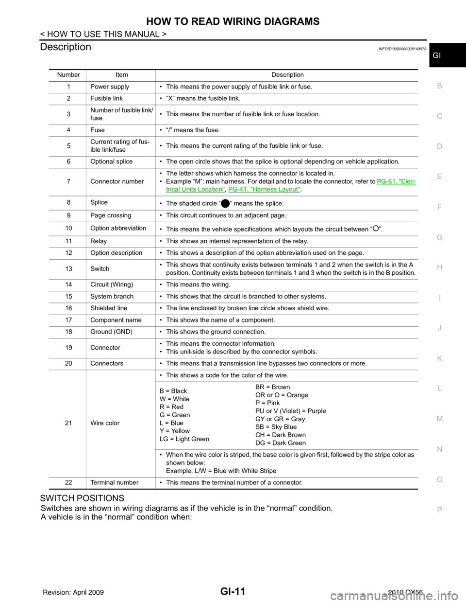
DescriptionINFOID:0000000005149578
SWITCH POSITIONS
Switches are shown in wiring diagrams as if the vehicle is in the “normal” condition.
A vehicle is in the “normal” condition when:
Number Item Description
1 Power supply • This means the power supply of fusible link or fuse.
2 Fusible link • “X” means the fusible link.
3 Number of fusible link/
fuse • This means the number of fusible link or fuse location.
4 Fuse • “/” means the fuse.
5 Current rating of fus-
ible link/fuse • This means the current rating of the fusible link or fuse.
6 Optional splice • The open circle shows that the splice is optional depending on vehicle application.
7 Connector number • The letter shows which harness the connector is located in.
• Example “M”: main harness. For detail and to locate the connector, refer to
PG-61, "
Elec-
trical Units Location", PG-41, "Harness Layout".
8Splice • The shaded circle “ ” means the splice.
9 Page crossing • This circuit continues to an adjacent page.
10 Option abbreviation • This means the vehicle specifications which layouts the circuit between “ ”.
11 Relay • This shows an internal representation of the relay.
12 Option description • This shows a description of the option abbreviation used on the page.
13 Switch • This shows that continuity exists between terminals 1 and 2 when the switch is in the A
position. Continuity exists between terminals 1 and 3 when the switch is in the B position.
14 Circuit (Wiring) • This means the wiring.
15 System branch • This shows that the circuit is branched to other systems.
16 Shielded line • The line enclosed by broken line circle shows shield wire.
17 Component name • This shows the name of a component.
18 Ground (GND) • This shows the ground connection.
19 Connector • This means the connector information.
• This unit-side is described by the connector symbols.
20 Connectors • This means that a transmission line bypasses two connectors or more.
21 Wire color • This shows a code for the color of the wire.
B = Black
W = White
R = Red
G = Green
L = Blue
Y = Yellow
LG = Light Green BR = Brown
OR or O = Orange
P = Pink
PU or V (Violet) = Purple
GY or GR = Gray
SB = Sky Blue
CH = Dark Brown
DG = Dark Green
• When the wire color is striped, the base color is given first, followed by the stripe color as shown below:
Example: L/W = Blue with White Stripe
22 Terminal number • This means the terminal number of a connector.
Revision: April 20092010 QX56