Page 3035 of 4210
PWC-50
< COMPONENT DIAGNOSIS >
REAR POWER VENT WINDOW RELAY (CLOSE) CHECK
1. Disconnect rear power vent window switch.
2. Check continuity between rear power vent window relay
(CLOSE) connector M89 terminal 2 and rear power vent window
switch M95 terminal 4.
Is the inspection result normal?
YES >> Replace rear power vent window switch.
NO >> Repair or replace harness. 2 - 4
: Continuity should exist.
LIIA1569E
Revision: April 20092010 QX56
Page 3036 of 4210

POWER WINDOW MAIN SWITCHPWC-51
< ECU DIAGNOSIS >
C
DE
F
G H
I
J
L
M A
B
PWC
N
O P
ECU DIAGNOSIS
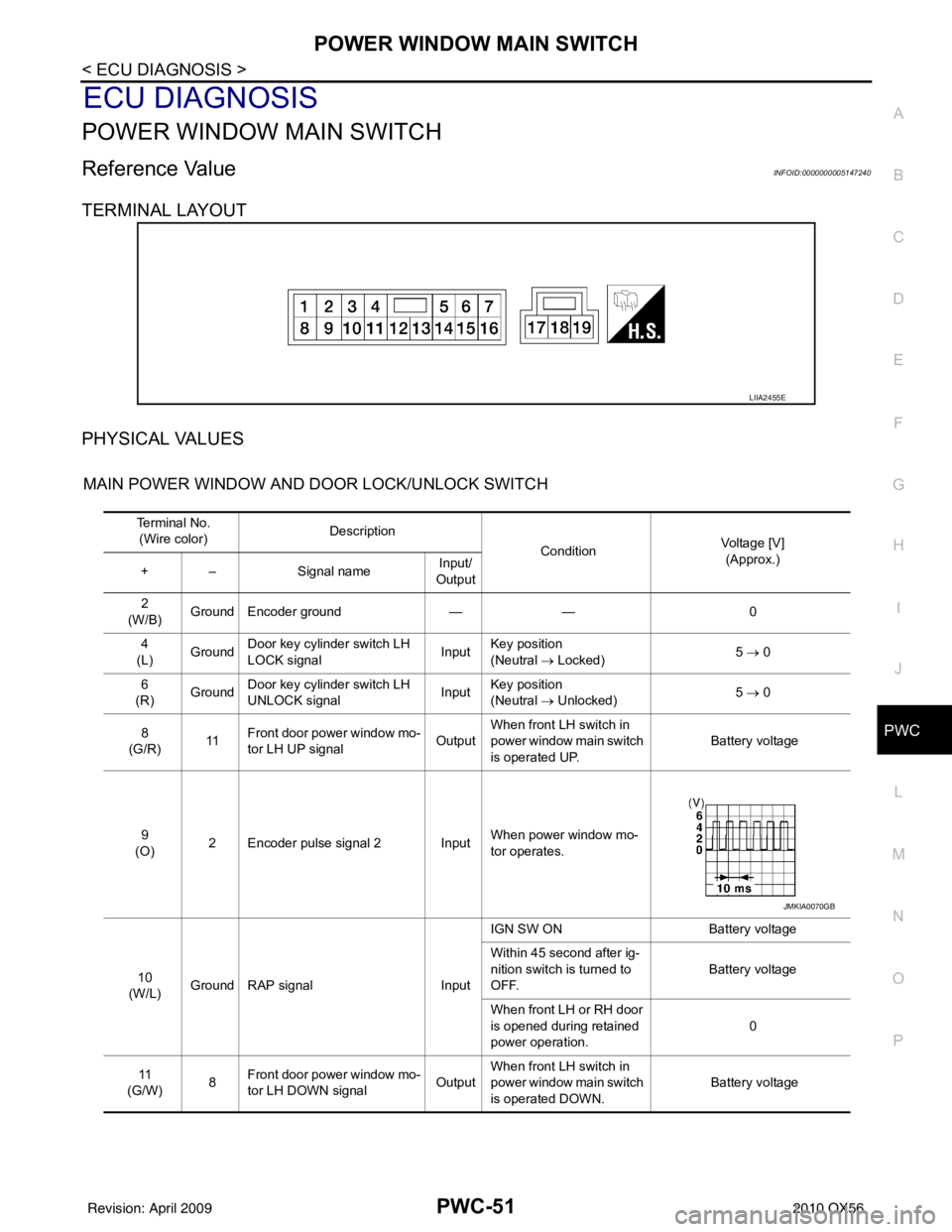
POWER WINDOW MAIN SWITCH
Reference Value INFOID:0000000005147240
TERMINAL LAYOUT
PHYSICAL VALUES
MAIN POWER WINDOW AND DOOR LOCK/UNLOCK SWITCH
LIIA2455E
Te r m i n a l N o . (Wire color) Description
ConditionVoltage [V]
(Approx.)
+ – Signal name Input/
Output
2
(W/B) Ground Encoder ground
—— 0
4
(L) Ground
Door key cylinder switch LH
LOCK signal Input
Key position
(Neutral
→ Locked) 5
→ 0
6
(R) Ground Door key cylinder switch LH
UNLOCK signal InputKey position
(Neutral
→ Unlocked) 5
→ 0
8
(G/R) 11Front door power window mo-
tor LH UP signal OutputWhen front LH switch in
power window main switch
is operated UP. Battery voltage
9
(O) 2 Encoder pulse signal 2 Input When power window mo-
tor operates.
10
(W/L) Ground RAP signal
InputIGN SW ON
Battery voltage
Within 45 second after ig-
nition switch is turned to
OFF. Battery voltage
When front LH or RH door
is opened during retained
power operation. 0
11
(G/W) 8
Front door power window mo-
tor LH DOWN signal OutputWhen front LH switch in
power window main switch
is operated DOWN. Battery voltage
JMKIA0070GB
Revision: April 20092010 QX56
Page 3037 of 4210
PWC-52
< ECU DIAGNOSIS >
POWER WINDOW MAIN SWITCH
13
(G/Y) 2 Encoder pulse signal 1 Input When power window mo-
tor operates.
14
(LG/W) Ground Power window serial link Input/
Output IGN SW ON or power win-
dow timer operating.
15
(BR) Ground Encoder power supply Output When ignition switch ON or
power window timer oper-
ates.10
17
(B) Ground Ground
—— 0
19
(W/R) Ground Battery power supply
Input— Battery voltage
Te r m i n a l N o .
(Wire color) Description
ConditionVoltage [V]
(Approx.)
+ – Signal name Input/
Output
JMKIA0070GB
JPMIA0013GB
Revision: April 20092010 QX56
Page 3038 of 4210
POWER WINDOW MAIN SWITCHPWC-53
< ECU DIAGNOSIS >
C
DE
F
G H
I
J
L
M A
B
PWC
N
O P
Wiring DiagramINFOID:0000000005147241
ABKWA0485GB
Revision: April 20092010 QX56
Page 3039 of 4210
PWC-54
< ECU DIAGNOSIS >
POWER WINDOW MAIN SWITCH
ABKWA0453GB
Revision: April 20092010 QX56
Page 3040 of 4210
POWER WINDOW MAIN SWITCHPWC-55
< ECU DIAGNOSIS >
C
DE
F
G H
I
J
L
M A
B
PWC
N
O P
ABKIA1340GB
Revision: April 20092010 QX56
Page 3041 of 4210
PWC-56
< ECU DIAGNOSIS >
POWER WINDOW MAIN SWITCH
AAKIA0104GB
Revision: April 20092010 QX56
Page 3042 of 4210
POWER WINDOW MAIN SWITCHPWC-57
< ECU DIAGNOSIS >
C
DE
F
G H
I
J
L
M A
B
PWC
N
O P
ABKIA1341GB
Revision: April 20092010 QX56