2010 INFINITI QX56 window
[x] Cancel search: windowPage 3008 of 4210
ENCODERPWC-23
< COMPONENT DIAGNOSIS >
C
DE
F
G H
I
J
L
M A
B
PWC
N
O P
ENCODER
DRIVER SIDE
DRIVER SIDE : DescriptionINFOID:0000000005147197
Detects condition of the front power window motor LH operation and transmits to main power window and door
lock/unlock switch as pulse signal.
DRIVER SIDE : Componen t Function CheckINFOID:0000000005147198
1. CHECK ENCODER OPERATION
Does front door glass LH perform AUTO open/close operation normally when operating main power window
and door lock/unlock switch?
Is the inspection result normal?
YES >> Encoder operation is OK.
NO >> Refer to PWC-23, "
DRIVER SIDE : Diagnosis Procedure".
DRIVER SIDE : Diag nosis ProcedureINFOID:0000000005147199
Regarding Wiring Diagram information, refer to PWC-53, "Wiring Diagram".
1. CHECK ENCODER OPERATION
1. Turn ignition switch ON.
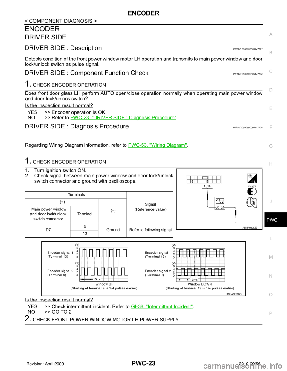
2. Check signal between main power window and door lock/unlock switch connector and ground with oscilloscope.
Is the inspection result normal?
YES >> Check intermittent incident. Refer to GI-38, "Intermittent Incident".
NO >> GO TO 2
2. CHECK FRONT POWER WINDOW MOTOR LH POWER SUPPLY
Te r m i n a l s
Signal
(Reference value)
(+)
(–)
Main power window
and door lock/unlock
switch connector Te r m i n a l
D7 9
Ground Refer to following signal
13
ALKIA0295ZZ
JMKIA0220GB
Revision: April 20092010 QX56
Page 3009 of 4210
PWC-24
< COMPONENT DIAGNOSIS >
ENCODER
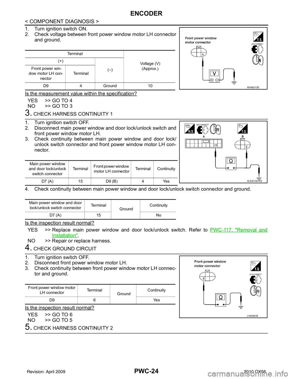
1. Turn ignition switch ON.
2. Check voltage between front power window motor LH connectorand ground.
Is the measurement value within the specification?
YES >> GO TO 4
NO >> GO TO 3
3. CHECK HARNESS CONTINUITY 1
1. Turn ignition switch OFF.
2. Disconnect main power window and door lock/unlock switch and front power window motor LH.
3. Check continuity between main power window and door lock/ unlock switch connector and front power window motor LH con-
nector.
4. Check continuity between main power window and door lock/unlock switch connector and ground.
Is the inspection result normal?
YES >> Replace main power window and door lock/unlock switch. Refer to PWC-117, "Removal and
Installation".
NO >> Repair or replace harness.
4. CHECK GROUND CIRCUIT
1. Turn ignition switch OFF.
2. Disconnect front power window motor LH.
3. Check continuity between front power window motor LH connec- tor and ground.
Is the inspection result normal?
YES >> GO TO 6
NO >> GO TO 5
5. CHECK HARNESS CONTINUITY 2
Te r m i n a l Voltage (V)(Approx.)
(+)
(–)
Front power win-
dow motor LH con- nector Te r m i n a l
D9 4Ground 10
WIIA0513E
Main power window
and door lock/unlock switch connector Te r m i n a l
Front power window
motor LH connector Terminal Continuity
D7 (A) 15 D9 (B) 4 Yes
Main power window and door lock/unlock switch connector Te r m i n a l
Ground Continuity
D7 (A) 15 No
ALKIA1021ZZ
Front power window motor
LH connector Terminal
Ground Continuity
D9 6 Yes
LIIA0923E
Revision: April 20092010 QX56
Page 3010 of 4210
ENCODERPWC-25
< COMPONENT DIAGNOSIS >
C
DE
F
G H
I
J
L
M A
B
PWC
N
O P
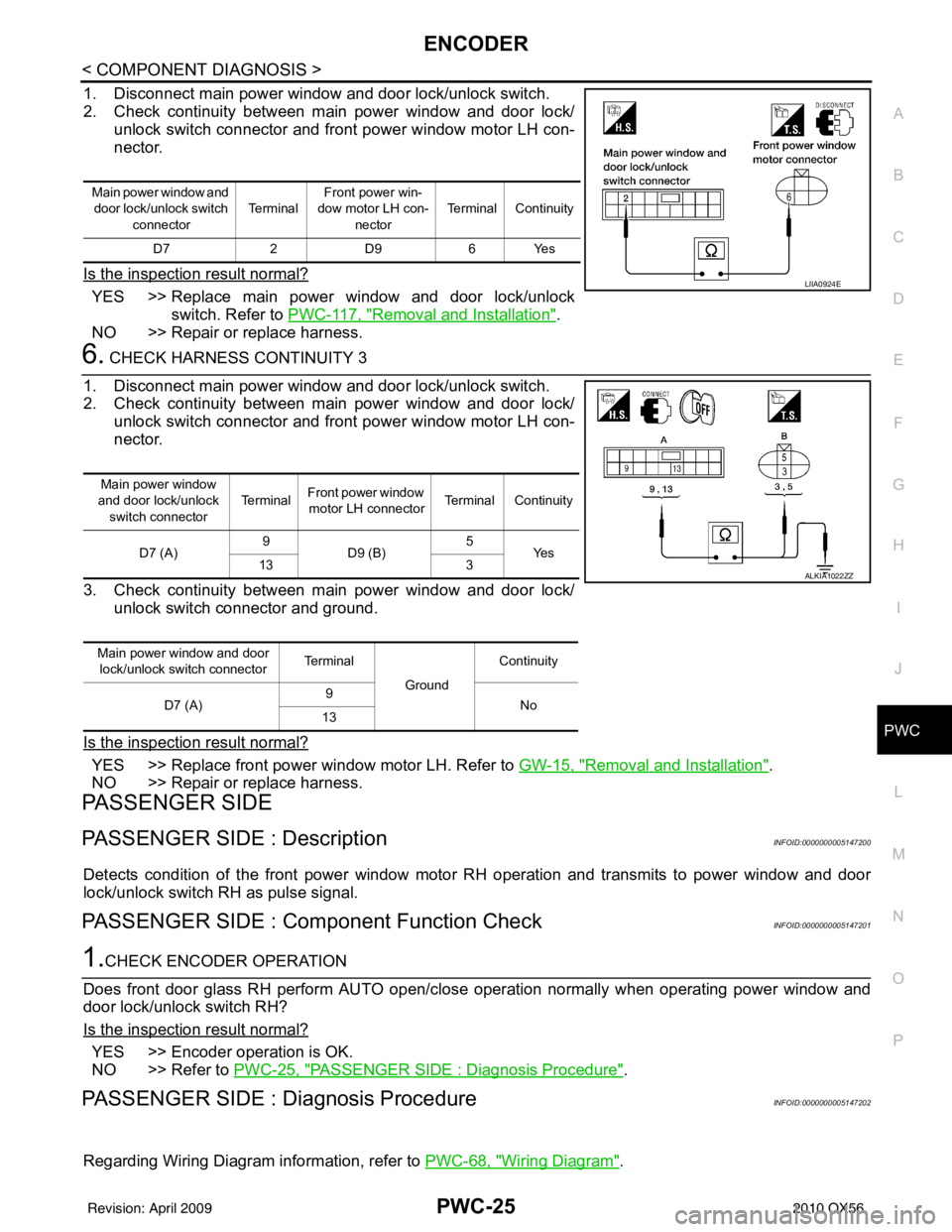
1. Disconnect main power window and door lock/unlock switch.
2. Check continuity between main power window and door lock/ unlock switch connector and front power window motor LH con-
nector.
Is the inspection result normal?
YES >> Replace main power window and door lock/unlock switch. Refer to PWC-117, "
Removal and Installation".
NO >> Repair or replace harness.
6. CHECK HARNESS CONTINUITY 3
1. Disconnect main power window and door lock/unlock switch.
2. Check continuity between main power window and door lock/ unlock switch connector and front power window motor LH con-
nector.
3. Check continuity between main power window and door lock/ unlock switch connector and ground.
Is the inspection result normal?
YES >> Replace front power wi ndow motor LH. Refer to GW-15, "Removal and Installation".
NO >> Repair or replace harness.
PASSENGER SIDE
PASSENGER SIDE : DescriptionINFOID:0000000005147200
Detects condition of the front power window motor RH operation and transmits to power window and door
lock/unlock switch RH as pulse signal.
PASSENGER SIDE : Comp onent Function CheckINFOID:0000000005147201
1.CHECK ENCODER OPERATION
Does front door glass RH perform AUTO open/close operation normally when operating power window and
door lock/unlock switch RH?
Is the inspection result normal?
YES >> Encoder operation is OK.
NO >> Refer to PWC-25, "
PASSENGER SIDE : Diagnosis Procedure".
PASSENGER SIDE : Dia gnosis ProcedureINFOID:0000000005147202
Regarding Wiring Diagram information, refer to PWC-68, "Wiring Diagram".
Main power window and
door lock/unlock switch
connector Te r m i n a l
Front power win-
dow motor LH con-
nector Terminal Continuity
D7 2 D9 6 Yes
LIIA0924E
Main power window
and door lock/unlock switch connector Te r m i n a l
Front power window
motor LH connector Terminal Continuity
D7 (A) 9
D9 (B) 5
Ye s
13 3
Main power window and door lock/unlock switch connector Te r m i n a l
GroundContinuity
D7 (A) 9
No
13
ALKIA1022ZZ
Revision: April 20092010 QX56
Page 3011 of 4210
PWC-26
< COMPONENT DIAGNOSIS >
ENCODER
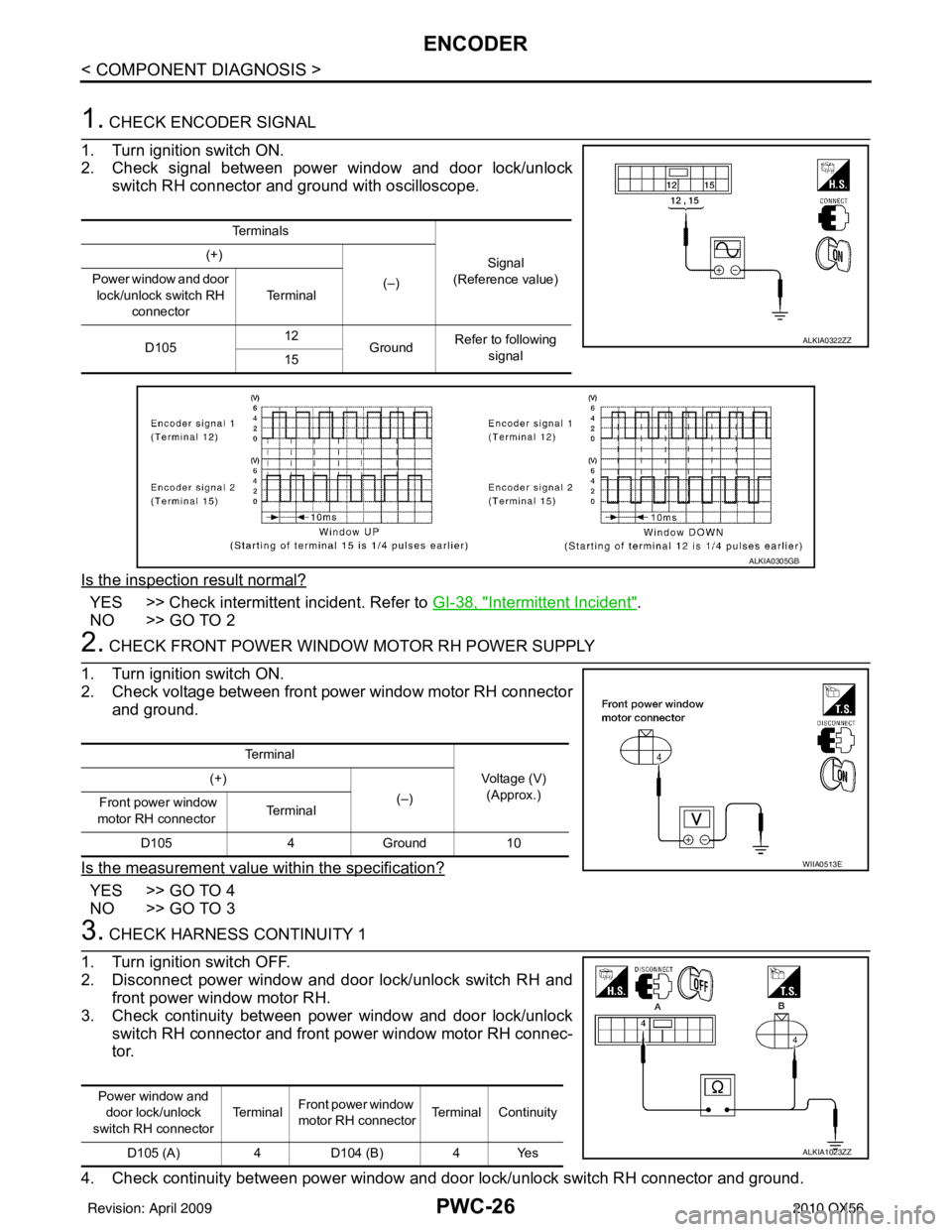
1. CHECK ENCODER SIGNAL
1. Turn ignition switch ON.
2. Check signal between power window and door lock/unlock switch RH connector and ground with oscilloscope.
Is the inspection result normal?
YES >> Check intermittent incident. Refer to GI-38, "Intermittent Incident".
NO >> GO TO 2
2. CHECK FRONT POWER WINDOW MOTOR RH POWER SUPPLY
1. Turn ignition switch ON.
2. Check voltage between front power window motor RH connector and ground.
Is the measurement value within the specification?
YES >> GO TO 4
NO >> GO TO 3
3. CHECK HARNESS CONTINUITY 1
1. Turn ignition switch OFF.
2. Disconnect power window and door lock/unlock switch RH and front power window motor RH.
3. Check continuity between power window and door lock/unlock switch RH connector and front power window motor RH connec-
tor.
4. Check continuity between power window and door lock/unlock switch RH connector and ground.
Te r m i n a l s
Signal
(Reference value)
(+)
(–)
Power window and door
lock/unlock switch RH connector Te r m i n a l
D105 12
Ground Refer to following
signal
15
ALKIA0322ZZ
ALKIA0305GB
Te r m i n a l
Voltage (V)(Approx.)
(+)
(–)
Front power window
motor RH connector Te r m i n a l
D105 4Ground 10
WIIA0513E
Power window and
door lock/unlock
switch RH connector Te r m i n a l
Front power window
motor RH connector Terminal Continuity
D105 (A) 4D104 (B) 4 Yes
ALKIA1023ZZ
Revision: April 20092010 QX56
Page 3012 of 4210
ENCODERPWC-27
< COMPONENT DIAGNOSIS >
C
DE
F
G H
I
J
L
M A
B
PWC
N
O P
Is the inspection result normal?
YES >> Replace power window and door lock/unlock switch RH. Refer to PWC-118, "Removal and Instal-
lation".
NO >> Repair or replace harness.
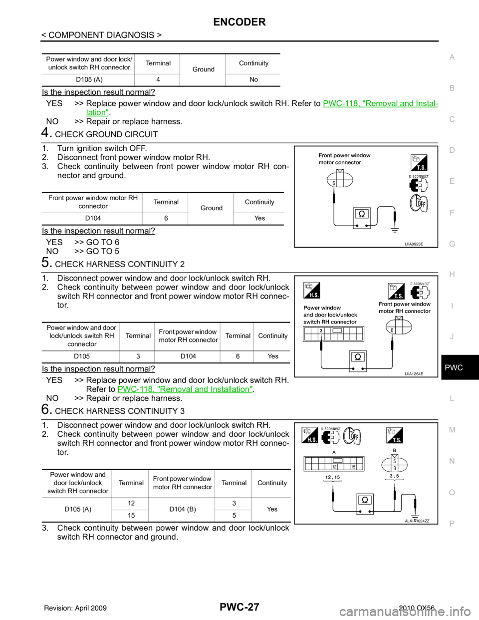
4. CHECK GROUND CIRCUIT
1. Turn ignition switch OFF.
2. Disconnect front power window motor RH.
3. Check continuity between front power window motor RH con- nector and ground.
Is the inspection result normal?
YES >> GO TO 6
NO >> GO TO 5
5. CHECK HARNESS CONTINUITY 2
1. Disconnect power window and door lock/unlock switch RH.
2. Check continuity between power window and door lock/unlock switch RH connector and front power window motor RH connec-
tor.
Is the inspection result normal?
YES >> Replace power window and door lock/unlock switch RH. Refer to PWC-118, "
Removal and Installation".
NO >> Repair or replace harness.
6. CHECK HARNESS CONTINUITY 3
1. Disconnect power window and door lock/unlock switch RH.
2. Check continuity between power window and door lock/unlock switch RH connector and front power window motor RH connec-
tor.
3. Check continuity between power window and door lock/unlock switch RH connector and ground.
Power window and door lock/
unlock switch RH connector Te r m i n a l
GroundContinuity
D105 (A) 4 No
Front power window motor RH
connector Terminal
GroundContinuity
D104 6 Yes
LIIA0923E
Power window and door
lock/unlock switch RH connector Te r m i n a l
Front power window
motor RH connector Terminal Continuity
D105 3D104 6 Yes
LIIA1264E
Power window and
door lock/unlock
switch RH connector Te r m i n a l
Front power window
motor RH connector Terminal Continuity
D105 (A) 12
D104 (B) 3
Ye s
15 5
ALKIA1024ZZ
Revision: April 20092010 QX56
Page 3013 of 4210
PWC-28
< COMPONENT DIAGNOSIS >
ENCODER
Is the inspection result normal?
YES >> Replace front power window motor RH. Refer to GW-15, "Removal and Installation".
NO >> Repair or replace harness.
REAR LH
REAR LH : DescriptionINFOID:0000000005147203
Detects condition of the front power window motor LH operation and transmits to main power window and door
lock/unlock switch as pulse signal.
REAR LH : Componen t Function CheckINFOID:0000000005147204
1. CHECK ENCODER OPERATION
Does front door glass LH perform AUTO open/close operation normally when operating main power window
and door lock/unlock switch?
Is the inspection result normal?
YES >> Encoder operation is OK.
NO >> Refer to PWC-31, "
REAR RH : Diagnosis Procedure".
REAR LH : Diagnosis ProcedureINFOID:0000000005147205
Regarding Wiring Diagram information, refer to PWC-53, "Wiring Diagram".
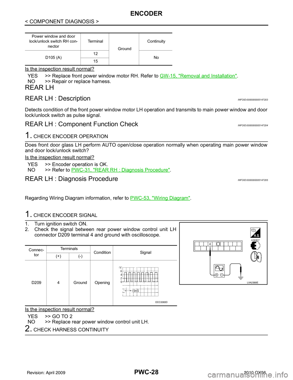
1. CHECK ENCODER SIGNAL
1. Turn ignition switch ON.
2. Check the signal between rear power window control unit LH connector D209 terminal 4 and ground with oscilloscope.
Is the inspection result normal?
YES >> GO TO 2
NO >> Replace rear power window control unit LH.
2. CHECK HARNESS CONTINUITY
Power window and door
lock/unlock switch RH con-
nector Te r m i n a l
GroundContinuity
D105 (A) 12
No
15
Connec-
tor Te r m i n a l s
Condition Signal
(+) (-)
D209 4 Ground Opening
LIIA2368E
OCC3383D
Revision: April 20092010 QX56
Page 3014 of 4210
ENCODERPWC-29
< COMPONENT DIAGNOSIS >
C
DE
F
G H
I
J
L
M A
B
PWC
N
O P
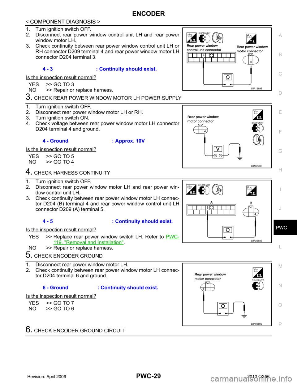
1. Turn ignition switch OFF.
2. Disconnect rear power window control unit LH and rear power window motor LH.
3. Check continuity between rear power window control unit LH or RH connector D209 terminal 4 and rear power window motor LH
connector D204 terminal 3.
Is the inspection result normal?
YES >> GO TO 3
NO >> Repair or replace harness.
3. CHECK REAR POWER WINDOW MOTOR LH POWER SUPPLY
1. Turn ignition switch OFF.
2. Disconnect rear power window motor LH or RH.
3. Turn ignition switch ON.
4. Check voltage between rear power window motor LH connector D204 terminal 4 and ground.
Is the inspection result normal?
YES >> GO TO 5
NO >> GO TO 4
4. CHECK HARNESS CONTINUITY
1. Turn ignition switch OFF.
2. Disconnect rear power window motor LH and rear power win- dow control unit LH.
3. Check continuity between rear power window motor LH connec- tor D204 (B) terminal 4 and rear power window control unit LH
connector D209 (A) terminal 5.
Is the inspection result normal?
YES >> Replace rear power window switch LH. Refer to PWC-
119, "Removal and Installation".
NO >> Repair or replace harness.
5. CHECK ENCODER GROUND
1. Disconnect rear power window motor LH.
2. Check continuity between rear power window motor LH connec- tor D204 terminal 6 and ground.
Is the inspection result normal?
YES >> GO TO 7
NO >> GO TO 6
6. CHECK ENCODER GROUND CIRCUIT 4 - 3
: Continuity should exist.
LIIA1389E
4 - Ground : Approx. 10V
LIIA0378E
4 - 5 : Continuity should exist.
LIIA2358E
6 - Ground: Continuity should exist.
LIIA0380E
Revision: April 20092010 QX56
Page 3015 of 4210
PWC-30
< COMPONENT DIAGNOSIS >
ENCODER
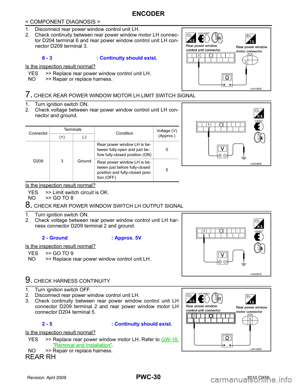
1. Disconnect rear power window control unit LH.
2. Check continuity between rear power window motor LH connec-tor D204 terminal 6 and rear power window control unit LH con-
nector D209 terminal 3.
Is the inspection result normal?
YES >> Replace rear power window control unit LH.
NO >> Repair or replace harness.
7. CHECK REAR POWER WINDOW MO TOR LH LIMIT SWITCH SIGNAL
1. Turn ignition switch ON.
2. Check voltage between rear power window control unit LH con- nector and ground.
Is the inspection result normal?
YES >> Limit switch circuit is OK.
NO >> GO TO 8
8. CHECK REAR POWER WINDOW SWITCH LH OUTPUT SIGNAL
1. Turn ignition switch ON.
2. Check voltage between rear power window control unit LH har- ness connector D209 terminal 2 and ground.
Is the inspection result normal?
YES >> GO TO 9
NO >> Replace rear power window control unit LH.
9. CHECK HARNESS CONTINUITY
1. Turn ignition switch OFF.
2. Disconnect rear power window control unit LH.
3. Check continuity between rear power window control unit LH connector D209 terminal 2 and rear power window motor LH
connector D204 terminal 5.
Is the inspection result normal?
YES >> Replace rear power window motor LH. Refer to GW-18,
"Removal and Installation".
NO >> Repair or replace harness.
REAR RH
6 - 3 : Continuity should exist.
LIIA1383E
ConnectorTe r m i n a l s
Condition Voltage (V)
(Approx.)
(+) (-)
D209 3 Ground Rear power window LH is be-
tween fully-open and just be-
fore fully-close
d position (ON) 0
Rear power window LH is be-
tween just before fully-closed
position and fully-closed posi-
tion (OFF) 5
LIIA2366E
2 - Ground
: Approx. 5V
LIIA2367E
2 - 5: Continuity should exist.
LIIA1385E
Revision: April 20092010 QX56