Page 3103 of 4210
PWC-118
< ON-VEHICLE REPAIR >
FRONT POWER WINDOW SWITCH
FRONT POWER WINDOW SWITCH
Removal and InstallationINFOID:0000000005147266
REMOVAL
1. Remove the front power window switch finisher (2) from the frontdoor finisher RH. Refer to INT-11, "
Removal and Installation".
: Pawl
2. Using a suitable tool (A), release the tabs and remove the front power window switch (1).
INSTALLATION
Installation is in the reverse order of removal.
ALKIA0857ZZ
Revision: April 20092010 QX56
Page 3104 of 4210
REAR POWER WINDOW SWITCHPWC-119
< ON-VEHICLE REPAIR >
C
DE
F
G H
I
J
L
M A
B
PWC
N
O P
REAR POWER WINDOW SWITCH
Removal and InstallationINFOID:0000000005147267
REMOVAL
1. Remove the rear power window switch finisher (1) from the rear door finisher. Refer to INT-11, "
Removal and Installation".
2. Using a suitable tool (A), release the tabs and remove the rear power window switch (2).
INSTALLATION
Installation is in the reverse order of removal.
ALKIA0860ZZ
Revision: April 20092010 QX56
Page 3105 of 4210
PWC-120
< ON-VEHICLE REPAIR >
REAR POWER VENT WINDOW SWITCH
REAR POWER VENT WINDOW SWITCH
Removal and InstallationINFOID:0000000005268493
REMOVAL
1. Remove the instrument lower panel LH, refer to IP-14, "Removal and Installation".
2. Using a suitable tool, release the upper and lower tabs , then remove the rear power vent window switch.
INSTALLATION
Installation is in the reverse order of removal.
1. Rear power vent window switch 2. Instrument lower panel LH Tab
ALKIA1619ZZ
Revision: April 20092010 QX56
Page 3136 of 4210

RF-8
< FUNCTION DIAGNOSIS >
DIAGNOSIS SYSTEM (BCM)
DIAGNOSIS SYSTEM (BCM)
COMMON ITEM
COMMON ITEM : CONSULT-III Function (BCM - COMMON ITEM)INFOID:0000000005370295
APPLICATION ITEM
CONSULT-III performs the following functions via CAN communication with BCM.
SYSTEM APPLICATION
BCM can perform the following functions for each system.
NOTE:
It can perform the diagnosis modes except the following for all sub system selection items.
RETAINED PWR
Diagnosis mode Function Description
WORK SUPPORT Changes the setting for each system function.
SELF-DIAG RESULTS Displays the diagnosis results judged by BCM. Refer to RF-31, "
DTCIndex".
CAN DIAG SUPPORT MNTR Monitors the reception status of CAN communication viewed from BCM.
DATA MONITOR The BCM input/output signals are displayed.
ACTIVE TEST The signals used to activate each device are forcibly supplied from BCM.
ECU IDENTIFICATION The BCM part number is displayed.
CONFIGURATION • Enables to read and save the vehicle specification.
• Enables to write the vehicle specification when replacing BCM.
System
Sub system selection item Diagnosis mode
WORK SUPPORT DATA MONITOR ACTIVE TEST
BCM BCM ×
Door lock DOOR LOCK ×××
Rear window defogger REAR DEFOGGER ×
Warning chime BUZZER ××
Interior room lamp timer INT LAMP ×××
Remote keyless entry system MULTI REMOTE ENT ××
Exterior lamp HEAD LAMP ×××
Wiper and washer WIPER ×××
Turn signal and hazard warning lamps FLASHER ××
Air conditioner AIR CONDITONER ×
Intelligent Key system INTELLIGENT KEY ×
Combination switch COMB SW ×
Immobilizer IMMU ××
Interior room lamp battery saver BATTERY SAVER ×××
Back door open TRUNK ××
RAP (retained accessory power) RETAINED PWR ×××
Signal buffer system SIGNAL BUFFER ××
TPMS (tire pressure monitoring sys-
tem) AIR PRESSURE MONITOR
×××
Vehicle security system THEFT ALM ×××
Panic alarm system PANIC ALARM ×
Revision: April 20092010 QX56
Page 3137 of 4210

DIAGNOSIS SYSTEM (BCM)RF-9
< FUNCTION DIAGNOSIS >
C
DE
F
G H
I
J
L
M A
B
RF
N
O P
RETAINED PWR : CONSULT-III Function (BCM - RETAINED PWR)INFOID:0000000005370296
DATA MONITOR
ACTIVE TEST
WORK SUPPORT
Monitor Item [Unit] Description
IGN ON SW [ON/OFF] Indicates condition of ignition switch.
DOOR SW-DR [ON/OFF] Indicates condition of front door switch LH.
DOOR SW-AS [ON/OFF] Indicates condition of front door switch RH.
Test Item Description
RETAINED PWR This test is able to supply RAP signal (powe
r) from BCM (body control module) to power window
system and power sunroof system (if equipped). Those systems can be operated when turning on
“RETAINED PWR” on CONSULT-III screen even if the ignition switch is turned OFF.
NOTE:
During this test, CONSULT-III can be operated with ignition switch in OFF position. “RETAINED
PWR” should be turned “ON” or “OFF” on CONSULT-III screen when ignition switch is ON. Then
turn ignition switch OFF to check retained power operation. CONSULT-III might be stuck if “RE-
TAINED PWR” is turned “ON” or “OFF” on CONSULT-III screen when ignition switch is OFF.
Work item Description
RETAINED PWR SET RAP signal’s power supply period can be changed by mode setting. Selects RAP signal’s power
supply period between three steps
• MODE1 (45 sec.)/MODE2 (OFF)/MODE 3 (2 min.).
Revision: April 20092010 QX56
Page 3150 of 4210

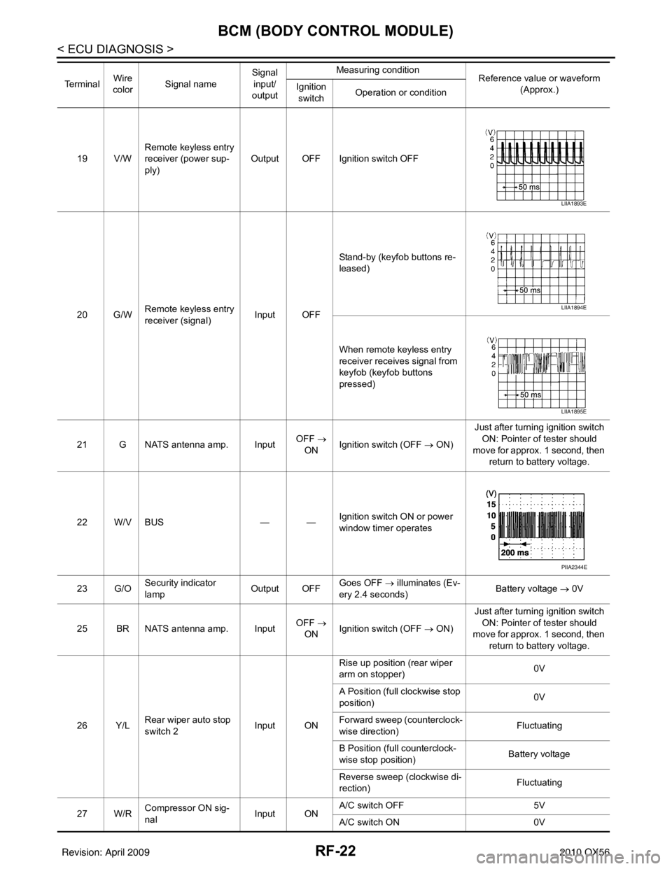
RF-22
< ECU DIAGNOSIS >
BCM (BODY CONTROL MODULE)
19 V/WRemote keyless entry
receiver (power sup-
ply) Output OFF Ignition switch OFF
20 G/W Remote keyless entry
receiver (signal) Input OFFStand-by (keyfob buttons re-
leased)
When remote keyless entry
receiver receives signal from
keyfob (keyfob buttons
pressed)
21 G NATS antenna amp. Input OFF
→
ON Ignition switch (OFF
→ ON)Just after turning ignition switch
ON: Pointer of tester should
move for approx. 1 second, then return to battery voltage.
22 W/V BUS — —Ignition switch ON or power
window timer operates
23 G/O Security indicator
lamp Output OFF
Goes OFF
→ illuminates (Ev-
ery 2.4 seconds) Battery voltage
→ 0V
25 BR NATS antenna amp. Input OFF
→
ON Ignition switch (OFF
→ ON)Just after turning ignition switch
ON: Pointer of tester should
move for approx. 1 second, then return to battery voltage.
26 Y/L Rear wiper auto stop
switch 2 Input ONRise up position (rear wiper
arm on stopper)
0V
A Position (full clockwise stop
position) 0V
Forward sweep (counterclock-
wise direction) Fluctuating
B Position (full counterclock-
wise stop position) Battery voltage
Reverse sweep (clockwise di-
rection) Fluctuating
27 W/R Compressor ON sig-
nal Input ONA/C switch OFF
5V
A/C switch ON 0V
Te r m i n a l
Wire
color Signal name Signal
input/
output Measuring condition
Reference value or waveform
(Approx.)
Ignition
switch Operation or condition
LIIA1893E
LIIA1894E
LIIA1895E
PIIA2344E
Revision: April 20092010 QX56
Page 3153 of 4210

BCM (BODY CONTROL MODULE)RF-25
< ECU DIAGNOSIS >
C
DE
F
G H
I
J
L
M A
B
RF
N
O P
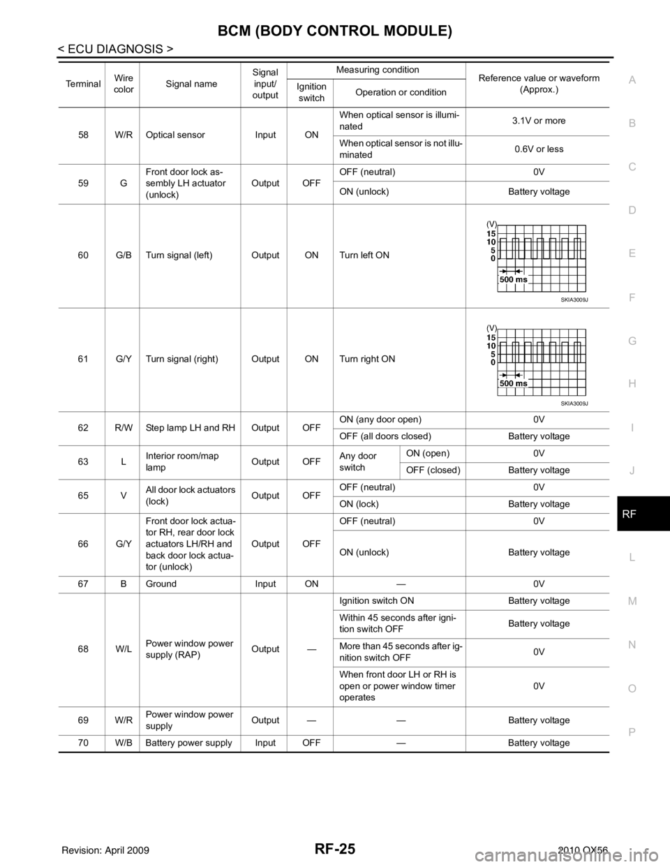
58 W/R Optical sensor Input ONWhen optical sensor is illumi-
nated
3.1V or more
When optical sensor is not illu-
minated 0.6V or less
59 G Front door lock as-
sembly LH actuator
(unlock) Output OFF
OFF (neutral)
0V
ON (unlock) Battery voltage
60 G/B Turn signal (left) Output ON Turn left ON
61 G/Y Turn signal (right) Output ON Turn right ON
62 R/W Step lamp LH and RH Output OFF ON (any door open)
0V
OFF (all doors closed) Battery voltage
63 L Interior room/map
lamp Output OFFAny door
switchON (open)
0V
OFF (closed) Battery voltage
65 V All door lock actuators
(lock) Output OFFOFF (neutral)
0V
ON (lock) Battery voltage
66 G/Y Front door lock actua-
tor RH, rear door lock
actuators LH/RH and
back door lock actua-
tor (unlock) Output OFF
OFF (neutral)
0V
ON (unlock) Battery voltage
67 B Ground Input ON—0V
68 W/L Power window power
supply (RAP) Output —Ignition switch ON
Battery voltage
Within 45 seconds after igni-
tion switch OFF Battery voltage
More than 45 seconds after ig-
nition switch OFF 0V
When front door LH or RH is
open or power window timer
operates 0V
69 W/R Power window power
supply
Output —
—Battery voltage
70 W/B Battery power supply Input OFF —Battery voltage
Te r m i n a l
Wire
color Signal name Signal
input/
output Measuring condition
Reference value or waveform
(Approx.)
Ignition
switch Operation or condition
SKIA3009J
SKIA3009J
Revision: April 20092010 QX56
Page 3358 of 4210
![INFINITI QX56 2010 Factory Service Manual PRE-INSPECTION FOR DIAGNOSTICSEC-7
< BASIC INSPECTION > [WITH INTELLIGENT KEY SYSTEM]
C
D
E
F
G H
I
J
L
M A
B
SEC
N
O P
PRE-INSPECTION FOR DIAGNOSTIC
Basic InspectionINFOID:0000000005147151
The engine INFINITI QX56 2010 Factory Service Manual PRE-INSPECTION FOR DIAGNOSTICSEC-7
< BASIC INSPECTION > [WITH INTELLIGENT KEY SYSTEM]
C
D
E
F
G H
I
J
L
M A
B
SEC
N
O P
PRE-INSPECTION FOR DIAGNOSTIC
Basic InspectionINFOID:0000000005147151
The engine](/manual-img/42/57032/w960_57032-3357.png)
PRE-INSPECTION FOR DIAGNOSTICSEC-7
< BASIC INSPECTION > [WITH INTELLIGENT KEY SYSTEM]
C
D
E
F
G H
I
J
L
M A
B
SEC
N
O P
PRE-INSPECTION FOR DIAGNOSTIC
Basic InspectionINFOID:0000000005147151
The engine start function, door lock function, power di stribution system and NATS-IVIS/NVIS in the Intelligent
Key system are closely related to each other regarding control. Narrow down the functional area in question
by performing basic inspection to i dentify which function is malfunctioning. The vehicle security function can
operate only when the door lock and power distribution system are operating normally. Therefore, it is easy to
identify any factor unique to the vehicle security system by performing the vehicle security operation check
after basic inspection.
1.CHECK DOOR LOCK OPERATION
Check the door lock for normal operation with the Intelligent Key controller and door request switch.
Successful door lock operation with the Intelligent Key and request SW indicates that the remote keyless entry
receiver and inside key antenna required for engine start are functioning normally.
Identify the malfunctioning point by referring to the DLK section if the door cannot be unlocked.
Can the door be locked with the Intelligent Key and door request switch?
YES >> GO TO 2.
NO >> Refer to DLK-210, "
Symptom Table".
2.CHECK ENGINE STARTING
Check that the engine starts when operating the Intelligent Key.
Does the engine start?
YES >> GO TO 3.
NO >> Refer to SEC-115, "
Symptom Table".
3.CHECK STEERING LOCKING
Does the steering lock when operating door switch after switching the power supply from ON position (or ACC
position) to LOCK position?
If door switch is malfunctioning, BC M cannot lock the steering. If BCM does not detect DTC, steering lock unit
is normal.
Does steering lock?
YES >> GO TO 4.
NO >> Refer to DLK-71, "
ComponentFunctionCheck".
4.CHECK IGNITION KNOB SWITCH OPERATION
Press ignition knob to check switch operation.
Does the combination meter display any message?
YES >> GO TO 5.
NO >> Refer to SEC-53, "
Ignition Knob Switch Check".
5.CHECK VEHICLE SECURITY SYSTEM
Check the vehicle security system for normal operation.
The vehicle security function can operate only when t he door lock and power distribution functions are operat-
ing normally.
Therefore, it is easy to identify any factor unique to the vehicle security by performing the vehicle security
operation check after this basic inspection.
>> Go to SEC-7, "
Vehicle Security Operation Check".
Vehicle Security Operation CheckINFOID:0000000005147152
1.INSPECTION START
Turn ignition switch “OFF”.
NOTE:
Before starting operation check, open front windows.
>> GO TO 2.
Revision: April 20092010 QX56