Page 3062 of 4210
FRONT POWER WINDOW SWITCHPWC-77
< ECU DIAGNOSIS >
C
DE
F
G H
I
J
L
M A
B
PWC
N
O P
ABKIA1441GB
Revision: April 20092010 QX56
Page 3063 of 4210
PWC-78
< ECU DIAGNOSIS >
FRONT POWER WINDOW SWITCH
ABKIA0016GB
Revision: April 20092010 QX56
Page 3064 of 4210
FRONT POWER WINDOW SWITCHPWC-79
< ECU DIAGNOSIS >
C
DE
F
G H
I
J
L
M A
B
PWC
N
O P
Fail SafeINFOID:0000000005147245
FAIL-SAFE CONTROL
Switches to fail-safe control when malfunction is detected in encoder signal that detects up/down speed and
direction of door glass. Switches to fail-safe cont rol when error beyond regulation value is detected between
the fully closed position and the actual position of the glass.
ABKIA0172GB
Revision: April 20092010 QX56
Page 3065 of 4210

PWC-80
< ECU DIAGNOSIS >
FRONT POWER WINDOW SWITCH
It changes to condition before initialization and the following functions do not operate when switched to fail-
safe control.
• Auto-up operation
• Anti-pinch function
• Retained power function
Perform initial operation to recover when switched to fa il-safe mode. However, it switches back to fail-safe
control when malfunction is found in power window switch or in motor.
Error Error condition
Pulse sensor malfunction When only one side of pulse signal is being detected for more than the specified value.
Both pulse sensors mal-
function When both pulse signals have not been detected for more than the specified value during glass open/
close operation.
Pulse direction malfunction When the pulse signal that is detected during glass open/close operation detects the opposite condition
of power window motor operating direction.
Glass recognition position
malfunction 1 When it detects the error between glass fully closed position in power window switch memory and actual
fully closed position during glass open/close operation is more than the specified value.
Glass recognition position
malfunction 2 When it detects pulse count more than the value of glass full stroke during glass open/close operation.
Malfunction of not yet up-
dated closed position of
glass When glass open/close operation is continuously performed without fully closing more than the specified
value (approximately 10 strokes).
Revision: April 20092010 QX56
Page 3071 of 4210

PWC-86
< ECU DIAGNOSIS >
BCM (BODY CONTROL MODULE)
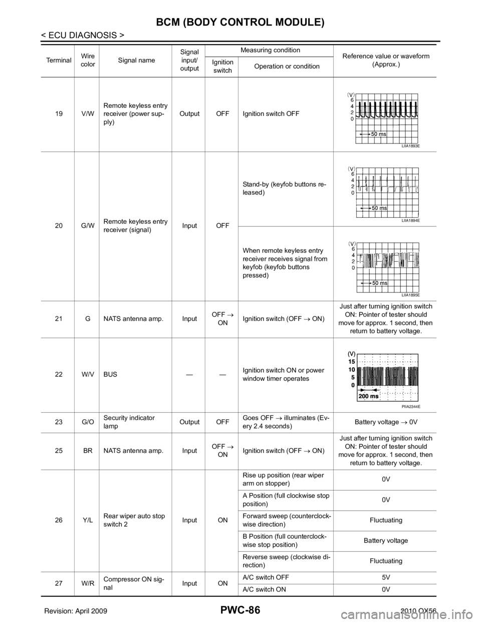
19 V/WRemote keyless entry
receiver (power sup-
ply) Output OFF Ignition switch OFF
20 G/W Remote keyless entry
receiver (signal) Input OFFStand-by (keyfob buttons re-
leased)
When remote keyless entry
receiver receives signal from
keyfob (keyfob buttons
pressed)
21 G NATS antenna amp. Input OFF
→
ON Ignition switch (OFF
→ ON)Just after turning ignition switch
ON: Pointer of tester should
move for approx. 1 second, then return to battery voltage.
22 W/V BUS — —Ignition switch ON or power
window timer operates
23 G/O Security indicator
lamp Output OFF
Goes OFF
→ illuminates (Ev-
ery 2.4 seconds) Battery voltage
→ 0V
25 BR NATS antenna amp. Input OFF
→
ON Ignition switch (OFF
→ ON)Just after turning ignition switch
ON: Pointer of tester should
move for approx. 1 second, then return to battery voltage.
26 Y/L Rear wiper auto stop
switch 2 Input ONRise up position (rear wiper
arm on stopper)
0V
A Position (full clockwise stop
position) 0V
Forward sweep (counterclock-
wise direction) Fluctuating
B Position (full counterclock-
wise stop position) Battery voltage
Reverse sweep (clockwise di-
rection) Fluctuating
27 W/R Compressor ON sig-
nal Input ONA/C switch OFF
5V
A/C switch ON 0V
Te r m i n a l
Wire
color Signal name Signal
input/
output Measuring condition
Reference value or waveform
(Approx.)
Ignition
switch Operation or condition
LIIA1893E
LIIA1894E
LIIA1895E
PIIA2344E
Revision: April 20092010 QX56
Page 3074 of 4210

BCM (BODY CONTROL MODULE)PWC-89
< ECU DIAGNOSIS >
C
DE
F
G H
I
J
L
M A
B
PWC
N
O P
58 W/R Optical sensor Input ONWhen optical sensor is illumi-
nated
3.1V or more
When optical sensor is not illu-
minated 0.6V or less
59 G Front door lock as-
sembly LH actuator
(unlock) Output OFF
OFF (neutral)
0V
ON (unlock) Battery voltage
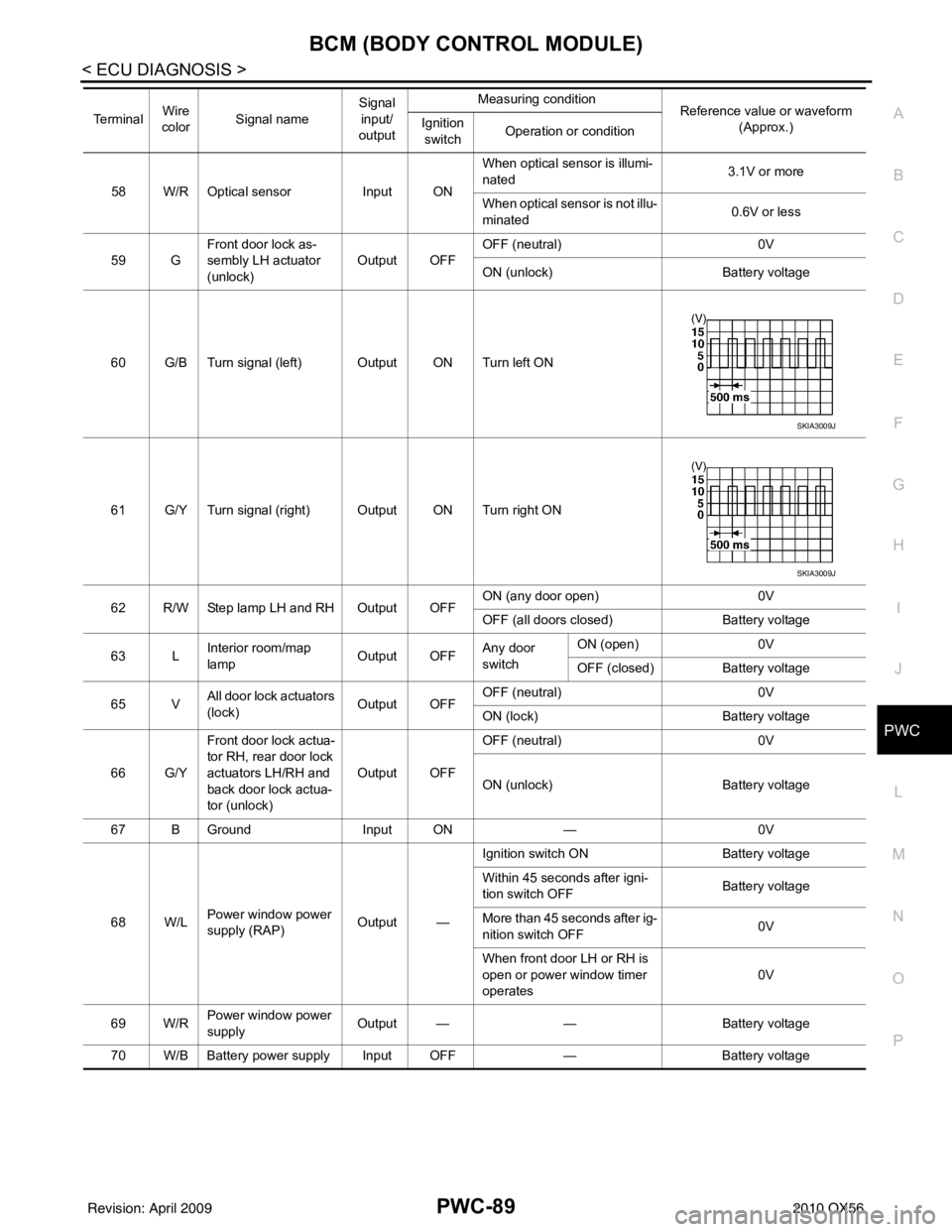
60 G/B Turn signal (left) Output ON Turn left ON
61 G/Y Turn signal (right) Output ON Turn right ON
62 R/W Step lamp LH and RH Output OFF ON (any door open)
0V
OFF (all doors closed) Battery voltage
63 L Interior room/map
lamp Output OFFAny door
switchON (open)
0V
OFF (closed) Battery voltage
65 V All door lock actuators
(lock) Output OFFOFF (neutral)
0V
ON (lock) Battery voltage
66 G/Y Front door lock actua-
tor RH, rear door lock
actuators LH/RH and
back door lock actua-
tor (unlock) Output OFF
OFF (neutral)
0V
ON (unlock) Battery voltage
67 B Ground Input ON—0V
68 W/L Power window power
supply (RAP) Output —Ignition switch ON
Battery voltage
Within 45 seconds after igni-
tion switch OFF Battery voltage
More than 45 seconds after ig-
nition switch OFF 0V
When front door LH or RH is
open or power window timer
operates 0V
69 W/R Power window power
supply
Output —
—Battery voltage
70 W/B Battery power supply Input OFF —Battery voltage
Te r m i n a l
Wire
color Signal name Signal
input/
output Measuring condition
Reference value or waveform
(Approx.)
Ignition
switch Operation or condition
SKIA3009J
SKIA3009J
Revision: April 20092010 QX56
Page 3082 of 4210

NONE OF THE POWER WINDOWS CAN BE OPERATED USING ANY SWITCH
PWC-97
< SYMPTOM DIAGNOSIS >
C
D E
F
G H
I
J
L
M A
B
PWC
N
O P
SYMPTOM DIAGNOSIS
NONE OF THE POWER WINDOWS CAN BE OPERATED USING ANY
SWITCH
Diagnosis ProcedureINFOID:0000000005147246
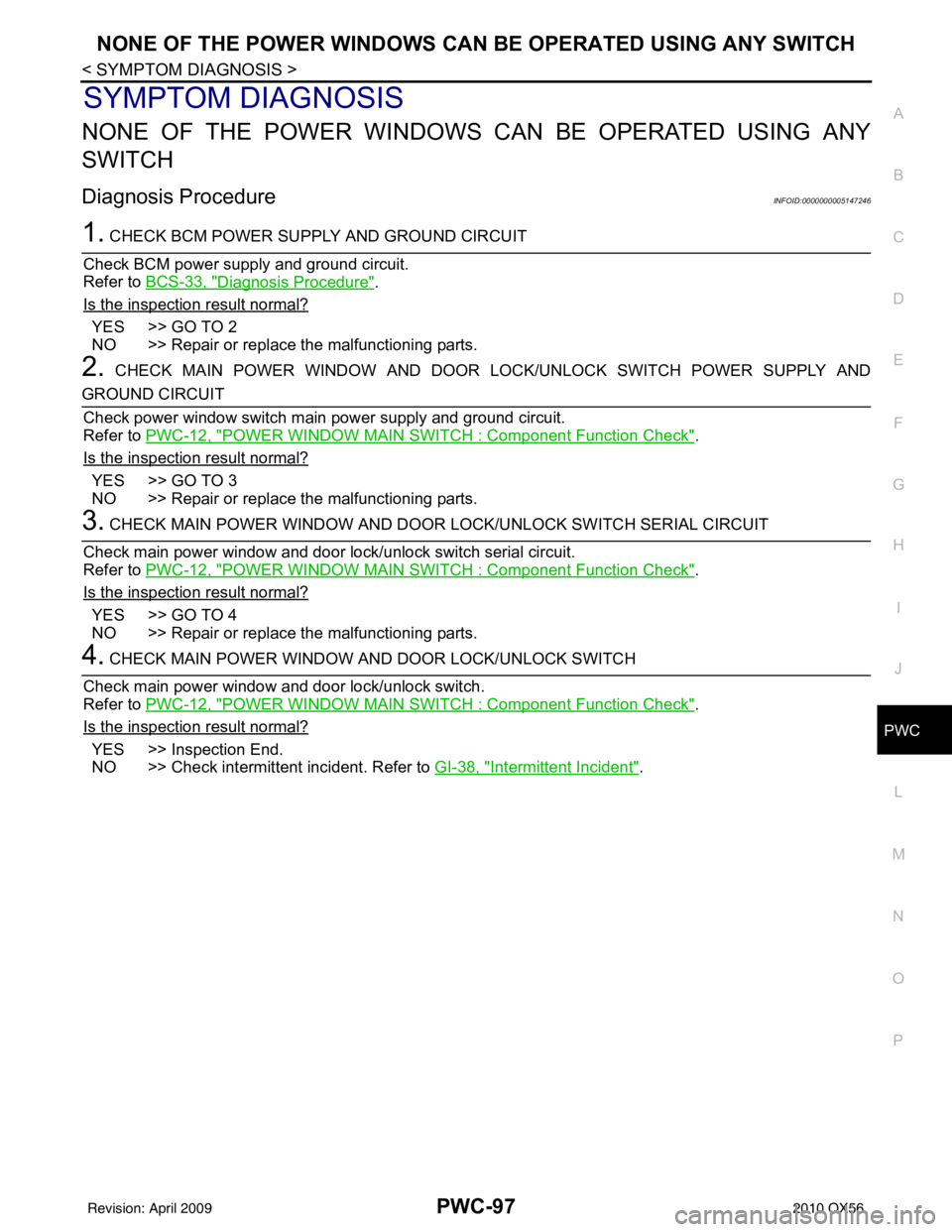
1. CHECK BCM POWER SUPPLY AND GROUND CIRCUIT
Check BCM power supply and ground circuit.
Refer to BCS-33, "
Diagnosis Procedure".
Is the inspection result normal?
YES >> GO TO 2
NO >> Repair or replace the malfunctioning parts.
2. CHECK MAIN POWER WINDOW AND DOOR LOCK/UNLOCK SWITCH POWER SUPPLY AND
GROUND CIRCUIT
Check power window switch main power supply and ground circuit.
Refer to PWC-12, "
POWER WINDOW MAIN SWITCH : Component Function Check".
Is the inspection result normal?
YES >> GO TO 3
NO >> Repair or replace the malfunctioning parts.
3. CHECK MAIN POWER WINDOW AND DOOR LOCK/UNLOCK SWITCH SERIAL CIRCUIT
Check main power window and door lock/unlock switch serial circuit.
Refer to PWC-12, "
POWER WINDOW MAIN SWITCH : Component Function Check".
Is the inspection result normal?
YES >> GO TO 4
NO >> Repair or replace the malfunctioning parts.
4. CHECK MAIN POWER WINDOW A ND DOOR LOCK/UNLOCK SWITCH
Check main power window and door lock/unlock switch.
Refer to PWC-12, "
POWER WINDOW MAIN SWITCH : Component Function Check".
Is the inspection result normal?
YES >> Inspection End.
NO >> Check intermittent incident. Refer to GI-38, "
Intermittent Incident".
Revision: April 20092010 QX56
Page 3083 of 4210
PWC-98
< SYMPTOM DIAGNOSIS >
DRIVER SIDE POWER WINDOW ALONE DOES NOT OPERATE
DRIVER SIDE POWER WINDOW ALONE DOES NOT OPERATE
Diagnosis ProcedureINFOID:0000000005147247
1. CHECK FRONT POWER WINDOW MOTOR LH
Check front power window motor LH.
Refer to PWC-17, "
DRIVER SIDE : Component Function Check".
Is the inspection result normal?
YES >> Inspection End.
NO >> Check intermittent incident. Refer to GI-38, "
Intermittent Incident".
Revision: April 20092010 QX56