2010 INFINITI QX56 windows
[x] Cancel search: windowsPage 2988 of 4210

PWC-3
C
DE
F
G H
I
J
L
M A
B
PWC
N
O P
ANTI-PINCH SYSTEM DOES NOT OPERATE
NORMALLY (PASSENGER SIDE) ................ ..
103
Diagnosis Procedure ........................................... ..103
ANTI-PINCH SYSTEM DOES NOT OPERATE
NORMALLY (REAR LH SIDE) .........................
104
Diagnosis Procedure ........................................... ..104
ANTI-PINCH SYSTEM DOES NOT OPERATE
NORMALLY (REAR RH SIDE) ........................
105
Diagnosis Procedure ........................................... ..105
AUTO OPERATION DOES NOT OPERATE
BUT MANUAL OPERATES NORMALLY
(DRIVER SIDE) .................................................
106
Diagnosis Procedure .............................................106
AUTO OPERATION DOES NOT OPERATE
BUT MANUAL OPERATES NORMALLY
(PASSENGER SIDE) ...................................... ..
107
Diagnosis Procedure ........................................... ..107
AUTO OPERATION DOES NOT OPERATE
BUT MANUAL OPERATES NORMALLY
(REAR LH SIDE) ..............................................
108
Diagnosis Procedure ........................................... ..108
AUTO OPERATION DOES NOT OPERATE
BUT MANUAL OPERATES NORMALLY
(REAR RH SIDE) ..............................................
109
Diagnosis Procedure ........................................... ..109
POWER WINDOW RETAINED POWER OP-
ERATION DOES NOT OPERATE PROPERLY
..
110
Diagnosis Procedure ........................................... ..110
DOES NOT OPERATE BY KEY CYLINDER
SWITCH ...........................................................
111
Diagnosis Procedure ........................................... ..111
KEYLESS POWER WINDOW DOWN DOES
NOT OPERATE ...............................................
112
Diagnosis Procedure .............................................112
POWER WINDOW LOCK SWITCH DOES
NOT FUNCTION ..............................................
113
Diagnosis Procedure .............................................113
REAR POWER VENT WINDOWS DO NOT
OPERATE .......................................................
114
Diagnosis Procedure .............................................114
PRECAUTION ............................................115
PRECAUTIONS ...............................................115
Precaution for Supplemental Restraint System
(SRS) "AIR BAG" and "SEAT BELT PRE-TEN-
SIONER" ............................................................. ..
115
Precaution Necessary for Steering Wheel Rota-
tion After Battery Disconnect .................................
115
ON-VEHICLE REPAIR ...............................117
POWER WINDOW MAIN SWITCH .................117
Removal and Installation ..................................... ..117
FRONT POWER WINDOW SWITCH ..............118
Removal and Installation .......................................118
REAR POWER WINDOW SWITCH ................119
Removal and Installation .......................................119
REAR POWER VENT WINDOW SWITCH .....120
Removal and Installation .......................................120
Revision: April 20092010 QX56
Page 2991 of 4210

PWC-6
< FUNCTION DIAGNOSIS >
POWER WINDOW SYSTEM
REAR POWER WINDOW CONTROL
INPUT/OUTPUT SIGNAL CHART
POWER WINDOW OPERATION
• Power window system is operable during the retained power operation timer after turning ignition switch ON
and OFF.
• Main power window and door lock/unlock switch can open/close all windows.
• Power window and door lock unlock switch RH & rear power window switches LH and RH can open/close the corresponding windows.
REAR POWER VENT WINDOW OPERATION
• Rear power vent window system is operable during the retained power operation timer after turning ignitionswitch ON and OFF.
• Rear power vent window switch can open/close the rear power vent window LH and RH.
POWER WINDOW AUTO-OPERATION
• AUTO UP/DOWN operation can be performed when main power window and door lock/unlock switch or
power window and door lock/unlock switch RH turns to AUTO.
• Main power window and door lock/unlock switch controls rear power window LH/RH auto-operation.
• Encoder continues detecting the movement of power window motor and transmits to front power window
switch LH/RH or rear power window control unit LH/RH as the encoder pulse signal while power window
motor is operating.
• Front power window switch LH/RH or rear power window control unit LH/RH reads the changes of encoder signal and stops AUTO operation when door glass is at fully opened/closed position.
• Power window motor is operable in case encoder is malfunctioning.
RETAINED POWER OPERATION
• Retained power operation is an additional power supply function that enables power window system to oper-
ate during the 45 seconds even when ignition switch is turned OFF
Retained power function cancel conditions
• Front door CLOSE (door switch OFF) →OPEN (door switch ON).
• When ignition switch is ON.
• When timer time passes. (45 seconds)
POWER WINDOW LOCK
The power window lock is designed to lock operation of all windows except for front door window LH.
When in the lock position, the power window lock signal is transmitted to power window and door lock/unlock
switch RH and rear power window control unit LH/RH by power window serial link. This prevents the power
window motor from operating.
Item Input signal to front power window
switch Front power window switch
function Actuator
Power window and
door lock/unlock
switch RH Front power window motor RH UP/
DOWN signal
Power window control Front power window motor RH
Encoder Encoder pulse signal
BCM RAP signal
Item Input signal to front power window
switch Front power window switch
function Actuator
Main power window
and door lock/un-
lock switch Rear power window motor LH/RH UP/
DOWN signal
Power window control Rear power window motor LH/RH
Rear power window
switch LH/RH
Rear power window motor LH/RH UP/
DOWN signal
Rear power window
control unit LH/RH Rear power window
motor control LH
RH UP/DOWN signal
Encoder Encoder pulse signal
BCM Power window serial link signal
Revision: April 20092010 QX56
Page 2992 of 4210
POWER WINDOW SYSTEMPWC-7
< FUNCTION DIAGNOSIS >
C
DE
F
G H
I
J
L
M A
B
PWC
N
O P
ANTI-PINCH OPERATION
• Pinch foreign material in the door glass during AUTO-U P operation, and it is the anti-pinch function that low-
ers the door glass 150 mm (5.91 in) or 2 seconds when detected.
• Encoder continues detecting the movement of power window motor and transmits to power window switch
as the encoder pulse signal while power window motor is operating.
• Resistance is applied to the power window motor rotation that changes the frequency of encoder pulse sig-
nal if foreign material is trapped in the door glass.
• Front power window switch LH/RH and rear power window control unit LH/RH controls to lower the window glass for 150 mm (5.91 in) or 2 seconds after it detects encoder pulse signal frequency change.
OPERATION CONDITION
• When all door glass AUTO-UP operation is performed ( anti-pinch function does not operate just before the
door glass closes and is fully closed)
NOTE:
Depending on environment and driving conditions, if a similar impact or load is applied to the door glass, it
may lower.
KEY CYLINDER SWITCH OPERATION
Hold the door key cylinder to the LOCK or UNLOCK dire ction for more than 1 second to OPEN or CLOSE front
power windows when ignition switch is OFF. In addition, it stops when key position is moved to NEUTRAL
when operating.
OPERATION CONDITION
• Ignition switch OFF
• Hold door key cylinder to LOCK position for more than 1 second to perform CLOSE operation of the door glass.
• Hold door key cylinder to UNLOCK position for more than 1 second to perform OPEN operation of the door glass.
KEYLESS POWER WINDOW DOWN OPERATION
Front power windows open when the unlock button on Intelligent Key is activated and kept pressed for more
than 3
(NOTE) seconds with the ignition switch OFF. The windows keep opening if the unlock button is continu-
ously pressed.
The power window opening stops when the following operations are performed:
• When the unlock button is kept pressed more than 15 seconds.
• When the ignition switch is turned ON while the power window opening is operated.
• When the unlock button is released.
While retained power operation is activated, ke yless power window down function cannot be operated.
NOTE:
Keyless power window down operation mode can be changed by “PW DOWN SET” mode in “WORK SUP-
PORT”. Refer to DLK-56, "
CONSULT-III Function (INTELLIGENT KEY)".
NOTE:
Use CONSULT-III to change settings.
MODE1 (3sec)/MODE2 (OFF)/MODE3 (5sec)
Revision: April 20092010 QX56
Page 3030 of 4210
REAR POWER VENT WINDOW MOTOR LH CIRCUIT CHECK
PWC-45
< COMPONENT DIAGNOSIS >
C
D E
F
G H
I
J
L
M A
B
PWC
N
O P
REAR POWER VENT WINDOW MOTOR LH CIRCUIT CHECK
DescriptionINFOID:0000000005147228
Rear power vent windows OPEN/CLOSE by receiving the signal from rear power vent window switch.
Diagnosis ProcedureINFOID:0000000005147229
Regarding Wiring Diagram information, refer to PWC-53, "Wiring Diagram".
1. CHECK REAR POWER VENT WINDOW LH SIGNAL
1. Turn ignition switch OFF.
2. Disconnect rear power vent window motor LH.
3. Turn ignition switch ON.
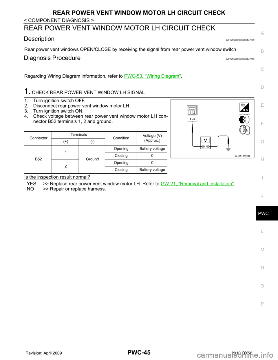
4. Check voltage between rear power vent window motor LH con- nector B52 terminals 1, 2 and ground.
Is the inspection result normal?
YES >> Replace rear power vent window motor LH. Refer to GW-21, "Removal and Installation".
NO >> Repair or replace harness.
Connector Te r m i n a l s
ConditionVoltage (V)
(Approx.)
(+) (-)
B52 1
Ground Opening Battery voltage
Closing 0
2 Opening
0
Closing Battery voltage
ALKIA1037GB
Revision: April 20092010 QX56
Page 3031 of 4210
PWC-46
< COMPONENT DIAGNOSIS >
REAR POWER VENT WINDOW MOTOR RH CIRCUIT CHECK
REAR POWER VENT WINDOW MOTOR RH CIRCUIT CHECK
DescriptionINFOID:0000000005147230
Rear power vent windows OPEN/CLOSE by receiving the signal from rear power vent window switch.
Diagnosis ProcedureINFOID:0000000005147231
Regarding Wiring Diagram information, refer to PWC-53, "Wiring Diagram".
1.CHECK REAR POWER VENT WINDOW SWITCH RH SIGNAL
1. Turn ignition switch OFF.
2. Disconnect rear power vent window motor RH.
3. Turn ignition switch ON.
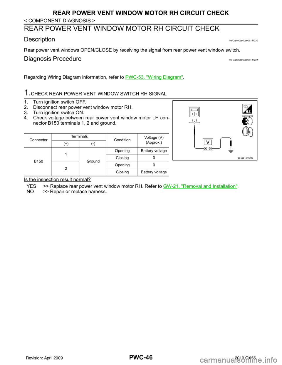
4. Check voltage between rear power vent window motor LH con- nector B150 terminals 1, 2 and ground.
Is the inspection result normal?
YES >> Replace rear power vent window motor RH. Refer to GW-21, "Removal and Installation".
NO >> Repair or replace harness.
Connector Te r m i n a l s
ConditionVoltage (V)
(Approx.)
(+) (-)
B150 1
Ground Opening Battery voltage
Closing 0
2 Opening
0
Closing Battery voltage
ALKIA1037GB
Revision: April 20092010 QX56
Page 3032 of 4210
REAR POWER VENT WINDOW RELAY (OPEN) CHECK
PWC-47
< COMPONENT DIAGNOSIS >
C
D E
F
G H
I
J
L
M A
B
PWC
N
O P
REAR POWER VENT WINDOW RELAY (OPEN) CHECK
DescriptionINFOID:0000000005147232
Rear power vent windows OPEN/CLOSE by receiving the signal from rear power vent window switch.
Diagnosis ProcedureINFOID:0000000005147233
Regarding Wiring Diagram information, refer to PWC-53, "Wiring Diagram".
1.CHECK REAR POWER VENT WINDOW RELAY (OPEN) POWER SUPPLY CIRCUIT
1. Turn ignition switch OFF.
2. Disconnect rear power vent window relay (OPEN).
3. Turn ignition switch ON.
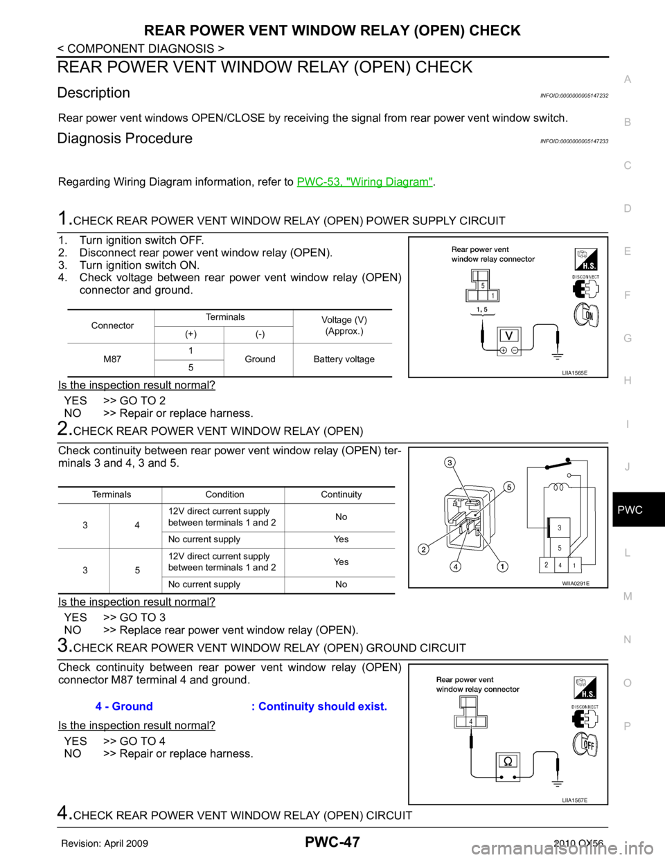
4. Check voltage between rear power vent window relay (OPEN) connector and ground.
Is the inspection result normal?
YES >> GO TO 2
NO >> Repair or replace harness.
2.CHECK REAR POWER VENT WINDOW RELAY (OPEN)
Check continuity between rear power vent window relay (OPEN) ter-
minals 3 and 4, 3 and 5.
Is the inspection result normal?
YES >> GO TO 3
NO >> Replace rear power vent window relay (OPEN).
3.CHECK REAR POWER VENT WINDOW RELAY (OPEN) GROUND CIRCUIT
Check continuity between rear power vent window relay (OPEN)
connector M87 terminal 4 and ground.
Is the inspection result normal?
YES >> GO TO 4
NO >> Repair or replace harness.
4.CHECK REAR POWER VENT WI NDOW RELAY (OPEN) CIRCUIT
ConnectorTe r m i n a l s
Voltage (V)
(Approx.)
(+) (-)
M87 1
Ground Battery voltage
5
LIIA1565E
Terminals Condition Continuity
34 12V direct current supply
between terminals 1 and 2
No
No current supply Yes
35 12V direct current supply
between terminals 1 and 2
Ye s
No current supply No
WIIA0291E
4 - Ground: Continuity should exist.
LIIA1567E
Revision: April 20092010 QX56
Page 3034 of 4210
REAR POWER VENT WINDOW RELAY (CLOSE) CHECKPWC-49
< COMPONENT DIAGNOSIS >
C
DE
F
G H
I
J
L
M A
B
PWC
N
O P
REAR POWER VENT WINDOW RELAY (CLOSE) CHECK
DescriptionINFOID:0000000005147234
Rear power vent windows OPEN/CLOSE by receiving the signal from rear power vent window switch.
Diagnosis ProcedureINFOID:0000000005147235
Regarding Wiring Diagram information, refer to PWC-53, "Wiring Diagram".
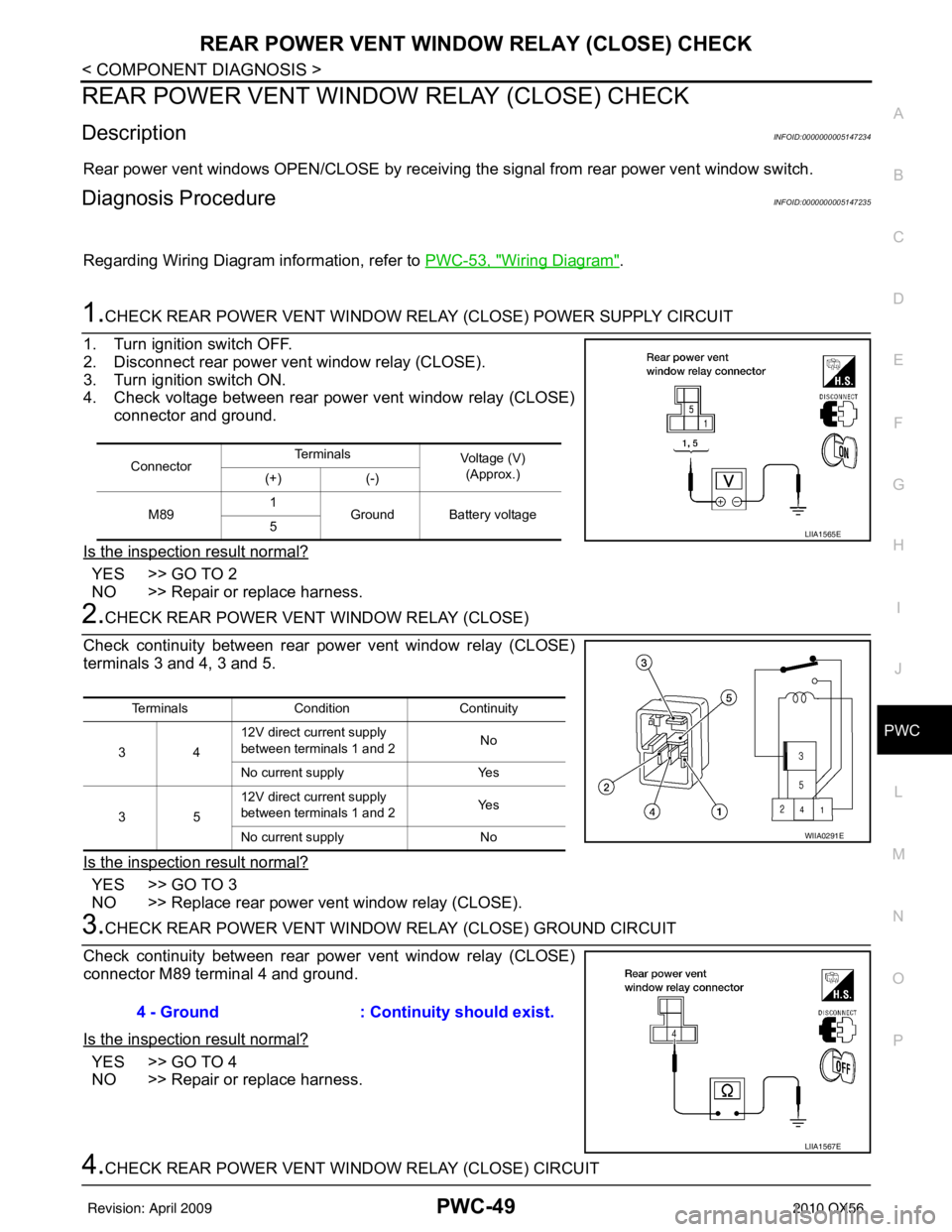
1.CHECK REAR POWER VENT WINDOW RELAY (CLOSE) POWER SUPPLY CIRCUIT
1. Turn ignition switch OFF.
2. Disconnect rear power vent window relay (CLOSE).
3. Turn ignition switch ON.
4. Check voltage between rear power vent window relay (CLOSE) connector and ground.
Is the inspection result normal?
YES >> GO TO 2
NO >> Repair or replace harness.
2.CHECK REAR POWER VENT WINDOW RELAY (CLOSE)
Check continuity between rear pow er vent window relay (CLOSE)
terminals 3 and 4, 3 and 5.
Is the inspection result normal?
YES >> GO TO 3
NO >> Replace rear power vent window relay (CLOSE).
3.CHECK REAR POWER VENT WINDOW RELAY (CLOSE) GROUND CIRCUIT
Check continuity between rear pow er vent window relay (CLOSE)
connector M89 terminal 4 and ground.
Is the inspection result normal?
YES >> GO TO 4
NO >> Repair or replace harness.
4.CHECK REAR POWER VENT WI NDOW RELAY (CLOSE) CIRCUIT
ConnectorTe r m i n a l s
Voltage (V)
(Approx.)
(+) (-)
M89 1
Ground Battery voltage
5
LIIA1565E
Terminals Condition Continuity
34 12V direct current supply
between terminals 1 and 2
No
No current supply Yes
35 12V direct current supply
between terminals 1 and 2
Ye s
No current supply No
WIIA0291E
4 - Ground: Continuity should exist.
LIIA1567E
Revision: April 20092010 QX56
Page 3082 of 4210
NONE OF THE POWER WINDOWS CAN BE OPERATED USING ANY SWITCH
PWC-97
< SYMPTOM DIAGNOSIS >
C
D E
F
G H
I
J
L
M A
B
PWC
N
O P
SYMPTOM DIAGNOSIS
NONE OF THE POWER WINDOWS CAN BE OPERATED USING ANY
SWITCH
Diagnosis ProcedureINFOID:0000000005147246
1. CHECK BCM POWER SUPPLY AND GROUND CIRCUIT
Check BCM power supply and ground circuit.
Refer to BCS-33, "
Diagnosis Procedure".
Is the inspection result normal?
YES >> GO TO 2
NO >> Repair or replace the malfunctioning parts.
2. CHECK MAIN POWER WINDOW AND DOOR LOCK/UNLOCK SWITCH POWER SUPPLY AND
GROUND CIRCUIT
Check power window switch main power supply and ground circuit.
Refer to PWC-12, "
POWER WINDOW MAIN SWITCH : Component Function Check".
Is the inspection result normal?
YES >> GO TO 3
NO >> Repair or replace the malfunctioning parts.
3. CHECK MAIN POWER WINDOW AND DOOR LOCK/UNLOCK SWITCH SERIAL CIRCUIT
Check main power window and door lock/unlock switch serial circuit.
Refer to PWC-12, "
POWER WINDOW MAIN SWITCH : Component Function Check".
Is the inspection result normal?
YES >> GO TO 4
NO >> Repair or replace the malfunctioning parts.
4. CHECK MAIN POWER WINDOW A ND DOOR LOCK/UNLOCK SWITCH
Check main power window and door lock/unlock switch.
Refer to PWC-12, "
POWER WINDOW MAIN SWITCH : Component Function Check".
Is the inspection result normal?
YES >> Inspection End.
NO >> Check intermittent incident. Refer to GI-38, "
Intermittent Incident".
Revision: April 20092010 QX56