2010 INFINITI QX56 Ignition switch
[x] Cancel search: Ignition switchPage 3478 of 4210
SN-6
< FUNCTION DIAGNOSIS >
REAR SONAR SYSTEM
FUNCTION DIAGNOSIS
REAR SONAR SYSTEM
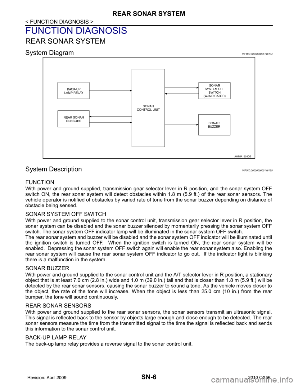
System DiagramINFOID:0000000005146184
System DescriptionINFOID:0000000005146185
FUNCTION
With power and ground supplied, transmission gear selector lever in R position, and the sonar system OFF
switch ON, the rear sonar system will detect obstacles withi n 1.8 m (5.9 ft.) of the rear sonar sensors. The
vehicle operator is notified of obstacles by varied rate of tone from the sonar buzzer depending on distance of
obstacle being sensed.
SONAR SYSTEM OFF SWITCH
With power and ground supplied to the sonar control unit, transmission gear selector lever in R position, the
sonar system can be disabled and the sonar buzzer silenced by momentarily pressing the sonar system OFF
switch. The sonar system OFF indicator lamp will be illuminated in the sonar system OFF switch.
The rear sonar system and buzzer will be disabled and t he sonar system OFF indicator will be illuminated until
the ignition switch is turned OFF. When the ignition switch is turned ON, the rear sonar system will be
enabled. Depressing the sonar system OFF switch again will enable the rear sonar system also. Enabling the
rear sonar system will cause the rear sonar system OFF i ndicator to go out. If the indicator light is blinking
there is a malfunction in the system.
SONAR BUZZER
With power and ground supplied to the sonar control unit and the A/T selector lever in R position, a stationary
object that is at least 7.0 cm (2.8 in.) wide and 1.0 m (39. 0 in.) tall and that is closer than 1.8 m (5.9 ft.) will be
detected by the rear sonar sensors, causing the sonar buzzer to sound a tone. As the vehicle moves closer to
the object, the rate of the tone will increase. When the object is less than 25.0 cm (10 in.) from the rear
bumper, the tone will sound continuously.
REAR SONAR SENSORS
With power and ground supplied to the rear sonar sens ors, the sonar sensors transmit an ultrasonic signal.
This signal is reflected back to the sensor by objects large enough and close enough to be detected. The rear
sonar sensors measure the time from the transmitted si gnal to the time the signal is reflected back and sends
this information to the sonar control unit.
BACK-UP LAMP RELAY
The back-up lamp relay provides a reverse signal to the sonar control unit.
AWNIA1905GB
Revision: April 20092010 QX56
Page 3480 of 4210
SN-8
< FUNCTION DIAGNOSIS >
REAR SONAR SYSTEM
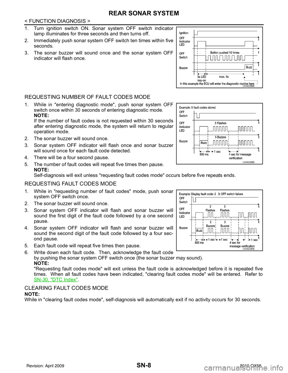
1. Turn ignition switch ON. Sonar system OFF switch indicatorlamp illuminates for three seconds and then turns off.
2. Immediately push sonar system OFF switch ten times within five
seconds.
3. The sonar buzzer will sound once and the sonar system OFF indicator will flash once.
REQUESTING NUMBER OF FAULT CODES MODE
1. While in "entering diagnostic mode", push sonar system OFF
switch once within 30 seconds of entering diagnostic mode.
NOTE:
If the number of fault codes is not requested within 30 seconds
after entering diagnostic mode, the system will return to regular
operation mode.
2. The sonar buzzer will sound once.
3. Sonar system OFF indicator will flash once and sonar buzzer will sound once for each fault code detected.
4. There will be a four second pause.
5. The number of fault codes will repeat five times then pause. NOTE:
Self-diagnosis will exit unless "requesting faul t codes mode" occurs before five repeats ends.
REQUESTING FAULT CODES MODE
1. While in "requesting number of fault codes" mode, push sonar
system OFF switch once.
2. The sonar buzzer will sound once.
3. Sonar system OFF indicator will flash and sonar buzzer will sound the first digit of the fault code followed by a one second
pause.
4. Sonar system OFF indicator will flash and sonar buzzer will sound the second digit of the fault code followed by a four sec-
ond pause.
5. Each fault code will repeat five times then pause.
6. Write down each fault code. Then, acknowledge the fault code by pushing the sonar system OFF switch once (the sonar buzzer may sound).
NOTE:
"Requesting fault codes mode" will exit unless the f ault code is acknowledged before it is repeated five
times. When all fault codes have been indicated, "clearing fault codes mode" will be entered. Refer to
SN-30, "
DTC Index".
CLEARING FAULT CODES MODE
NOTE:
While in "clearing fault codes mode", self-diagnosis will automatically exit if no activity occurs for 30 seconds.
LKIA0389E
LKIA0388E
LKIA0390E
Revision: April 20092010 QX56
Page 3482 of 4210
SN-10
< FUNCTION DIAGNOSIS >
FRONT AND REAR SONAR SYSTEM
FRONT AND REAR SONAR SYSTEM
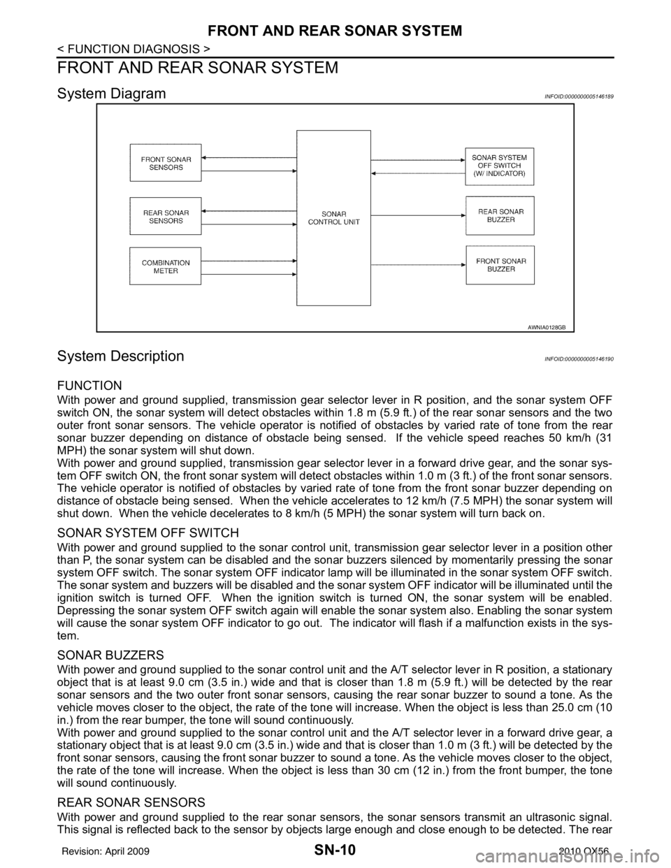
System DiagramINFOID:0000000005146189
System DescriptionINFOID:0000000005146190
FUNCTION
With power and ground supplied, transmission gear selector lever in R position, and the sonar system OFF
switch ON, the sonar system will detect obstacles within 1.8 m (5.9 ft.) of the rear sonar sensors and the two
outer front sonar sensors. The vehicle operator is notif ied of obstacles by varied rate of tone from the rear
sonar buzzer depending on distance of obstacle being sens ed. If the vehicle speed reaches 50 km/h (31
MPH) the sonar syst em will shut down.
With power and ground supplied, transmission gear selector lever in a forward drive gear, and the sonar sys-
tem OFF switch ON, the front sonar system will detect obstacles within 1.0 m (3 ft.) of the front sonar sensors.
The vehicle operator is notified of obstacles by varied rate of tone from the front sonar buzzer depending on
distance of obstacle being sensed. When the vehicle accelerates to 12 km/h (7.5 MPH) the sonar system will
shut down. When the vehicle decelerates to 8 km/h (5 MPH) the sonar system will turn back on.
SONAR SYSTEM OFF SWITCH
With power and ground supplied to the sonar control unit, transmission gear selector lever in a position other
than P, the sonar system can be di sabled and the sonar buzzers silenced by momentarily pressing the sonar
system OFF switch. The sonar system OFF indicator lamp will be illuminated in the sonar system OFF switch.
The sonar system and buzzers will be di sabled and the sonar system OFF indicator will be illuminated until the
ignition switch is turned OFF. When the ignition switch is turned ON, the sonar system will be enabled.
Depressing the sonar system OFF switch again will enabl e the sonar system also. Enabling the sonar system
will cause the sonar system OFF indicator to go out. The indicator will flash if a malfunction exists in the sys-
tem.
SONAR BUZZERS
With power and ground supplied to the sonar control unit and the A/T selector lever in R position, a stationary
object that is at least 9.0 cm (3.5 in.) wide and that is closer than 1.8 m (5.9 ft.) will be detected by the rear
sonar sensors and the two outer front sonar sensors, causing the rear sonar buzzer to sound a tone. As the
vehicle moves closer to the object, the rate of the tone will increase. When the object is less than 25.0 cm (10
in.) from the rear bumper, the tone will sound continuously.
With power and ground supplied to the sonar control unit and the A/T selector lever in a forward drive gear, a
stationary object that is at least 9.0 cm (3.5 in.) wide and that is closer than 1.0 m (3 ft.) will be detected by the
front sonar sensors, causing the front sonar buzzer to sound a tone. As the vehicle moves closer to the object,
the rate of the tone will increase. When the object is less than 30 cm (12 in.) from the front bumper, the tone
will sound continuously.
REAR SONAR SENSORS
With power and ground supplied to the rear sonar sens ors, the sonar sensors transmit an ultrasonic signal.
This signal is reflected back to the sensor by objects large enough and close enough to be detected. The rear
AWNIA0128GB
Revision: April 20092010 QX56
Page 3485 of 4210
SN
POWER SUPPLY AND GROUND CIRCUITSN-13
< COMPONENT DIAGNOSIS >
C
DE
F
G H
I
J
K L
M B A
O P
COMPONENT DIAGNOSIS
POWER SUPPLY AND GROUND CIRCUIT
Diagnosis Procedure (With Rear Sonar System)INFOID:0000000005146194
Regarding Wiring Diagram information, refer to SN-23, "Wiring Diagram".
INSPECTION FOR POWER SUPPLY AND GROUND CIRCUIT
1.CHECK FUSES
Check for blown rear sonar system fuses.
Are any fuses blown?
YES >> If fuse is blown, be sure to eliminate cause of malfunction before installing new fuse. Refer to GI-
41, "Circuit Inspection".
NO >> GO TO 2.
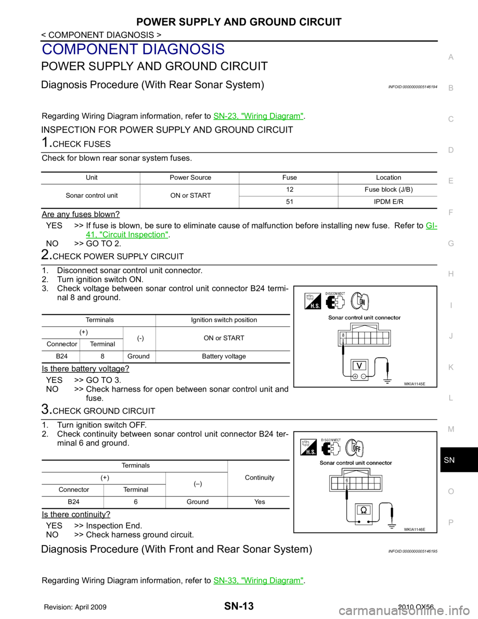
2.CHECK POWER SUPPLY CIRCUIT
1. Disconnect sonar control unit connector.
2. Turn ignition switch ON.
3. Check voltage between sonar control unit connector B24 termi- nal 8 and ground.
Is there battery voltage?
YES >> GO TO 3.
NO >> Check harness for open between sonar control unit and fuse.
3.CHECK GROUND CIRCUIT
1. Turn ignition switch OFF.
2. Check continuity between sonar control unit connector B24 ter- minal 6 and ground.
Is there continuity?
YES >> Inspection End.
NO >> Check harness ground circuit.
Diagnosis Procedure (With Front and Rear Sonar System)INFOID:0000000005146195
Regarding Wiring Diagram information, refer to SN-33, "Wiring Diagram".
UnitPower Source FuseLocation
Sonar control unit ON or START 12
Fuse block (J/B)
51 IPDM E/R
Terminals Ignition switch position
(+) (-) ON or START
Connector Terminal
B24 8 Ground Battery voltage
WKIA1145E
Te r m i n a l s
Continuity
(+)
(–)
Connector Terminal
B24 6 Ground Yes
WKIA1146E
Revision: April 20092010 QX56
Page 3486 of 4210
SN-14
< COMPONENT DIAGNOSIS >
POWER SUPPLY AND GROUND CIRCUIT
INSPECTION FOR POWER SUPPLY AND GROUND CIRCUIT
1.CHECK FUSES
Check for blown sonar system fuses.
Are any fuses blown?
YES >> If fuse is blown, be sure to eliminate cause of malfunction before installing new fuse. Refer to GI-
41, "Circuit Inspection".
NO >> GO TO 2.
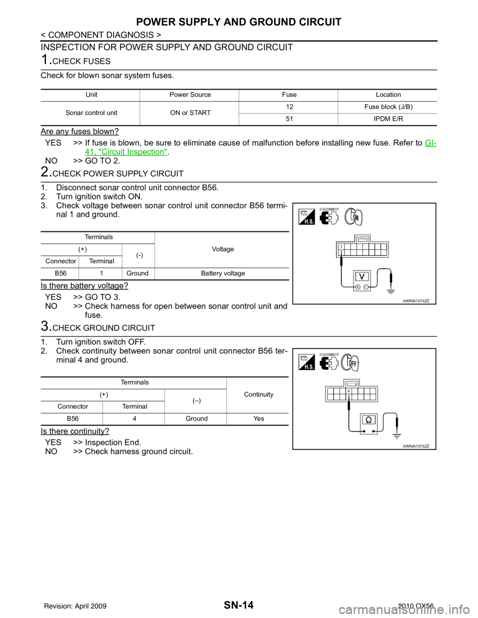
2.CHECK POWER SUPPLY CIRCUIT
1. Disconnect sonar control unit connector B56.
2. Turn ignition switch ON.
3. Check voltage between sonar control unit connector B56 termi- nal 1 and ground.
Is there battery voltage?
YES >> GO TO 3.
NO >> Check harness for open between sonar control unit and fuse.
3.CHECK GROUND CIRCUIT
1. Turn ignition switch OFF.
2. Check continuity between sonar control unit connector B56 ter-
minal 4 and ground.
Is there continuity?
YES >> Inspection End.
NO >> Check harness ground circuit.
Unit Power Source FuseLocation
Sonar control unit ON or START 12
Fuse block (J/B)
51 IPDM E/R
Te r m i n a l s
Vo l ta g e
(+)
(-)
Connector Terminal
B56 1 Ground Battery voltage
AWNIA1574ZZ
Te r m i n a l s
Continuity
(+)
(–)
Connector Terminal
B56 4Ground Yes
AWNIA1575ZZ
Revision: April 20092010 QX56
Page 3487 of 4210
SN
SONAR SENSOR CIRCUIT INSPECTIONSN-15
< COMPONENT DIAGNOSIS >
C
DE
F
G H
I
J
K L
M B A
O P
SONAR SENSOR CIRCUIT INSPECTION
DescriptionINFOID:0000000005146196
With power and ground supplied to the sonar sensors, the sonar sensors transmit an ultrasonic signal. This
signal is reflected back to the sensor by objec ts large enough and close enough to be detected. The sonar
sensors measure the time from the transmitted signal to the time the signal is reflected back and send this
information to the sonar control unit.
Diagnosis Procedure (With Rear Sonar System)INFOID:0000000005146197
Regarding Wiring Diagram information, refer to SN-23, "Wiring Diagram".
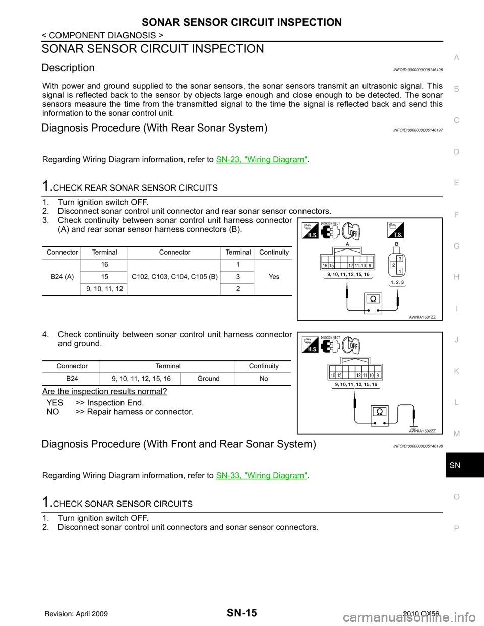
1.CHECK REAR SONAR SENSOR CIRCUITS
1. Turn ignition switch OFF.
2. Disconnect sonar control unit connector and rear sonar sensor connectors.
3. Check continuity between sonar control unit harness connector (A) and rear sonar sensor harness connectors (B).
4. Check continuity between sonar control unit harness connector and ground.
Are the inspection results normal?
YES >> Inspection End.
NO >> Repair harness or connector.
Diagnosis Procedure (With Front and Rear Sonar System)INFOID:0000000005146198
Regarding Wiring Diagram information, refer to SN-33, "Wiring Diagram".
1.CHECK SONAR SENSOR CIRCUITS
1. Turn ignition switch OFF.
2. Disconnect sonar control unit connec tors and sonar sensor connectors.
Connector TerminalConnectorTerminal Continuity
B24 (A) 16
C102, C103, C104, C105 (B) 1
Ye s
15 3
9, 10, 11, 12 2
AWNIA1501ZZ
ConnectorTerminalContinuity
B24 9, 10, 11, 12, 15, 16 Ground No
AWNIA1502ZZ
Revision: April 20092010 QX56
Page 3489 of 4210
SN
SONAR BUZZER CIRCUIT INSPECTIONSN-17
< COMPONENT DIAGNOSIS >
C
DE
F
G H
I
J
K L
M B A
O P
SONAR BUZZER CIRCUIT INSPECTION
DescriptionINFOID:0000000005146199
When the A/T selector lever is not it park or neutral, a stationary object will be detected by the sonar sensors
causing the front or rear sonar buzzer to sound a tone. As the vehicle moves closer to the object, the rate of
the tone will increase. When the object is very cl ose to the vehicle, the tone will sound continuously.
Diagnosis Procedure (With Rear Sonar System)INFOID:0000000005146200
Regarding Wiring Diagram information, refer to SN-23, "Wiring Diagram".
1.CHECK SONAR BUZZER
Refer to SN-18, "
Component Inspection".
Is the inspection result normal?
YES >> GO TO 2.
NO >> Replace sonar buzzer. Refer to SN-51, "
Removal and Installation".
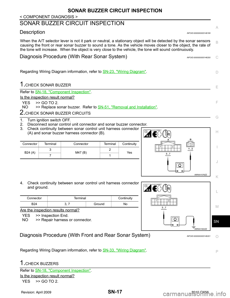
2.CHECK SONAR BUZZER CIRCUITS
1. Turn ignition switch OFF.
2. Disconnect sonar control unit connector and sonar buzzer connector.
3. Check continuity between sonar control unit harness connector (A) and sonar buzzer harness connector (B).
4. Check continuity between sonar control unit harness connector and ground.
Are the inspection results normal?
YES >> Inspection End.
NO >> Repair harness or connector.
Diagnosis Procedure (With Front and Rear Sonar System)INFOID:0000000005146201
Regarding Wiring Diagram information, refer to SN-33, "Wiring Diagram".
1.CHECK BUZZERS
Refer to SN-18, "
Component Inspection".
Is the inspection result normal?
YES >> GO TO 2.
Connector Terminal Connector Terminal Continuity
B24 (A) 3
M47 (B) 2
Ye s
71
AWNIA1576ZZ
Connector TerminalContinuity
B24 3, 7Ground No
AWNIA1504ZZ
Revision: April 20092010 QX56
Page 3490 of 4210
SN-18
< COMPONENT DIAGNOSIS >
SONAR BUZZER CIRCUIT INSPECTION
NO >> Replace buzzer. Refer to SN-51, "Removal and Installation".
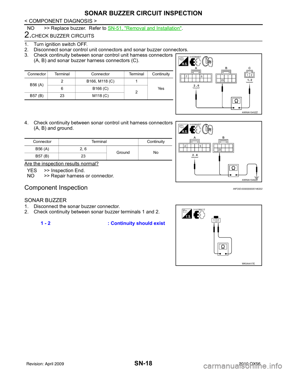
2.CHECK BUZZER CIRCUITS
1. Turn ignition switch OFF.
2. Disconnect sonar control unit connectors and sonar buzzer connectors.
3. Check continuity between sonar control unit harness connectors
(A, B) and sonar buzzer harness connectors (C).
4. Check continuity between sonar control unit harness connectors
(A, B) and ground.
Are the inspection results normal?
YES >> Inspection End.
NO >> Repair harness or connector.
Component InspectionINFOID:0000000005146202
SONAR BUZZER
1. Disconnect the sonar buzzer connector.
2. Check continuity between sonar buzzer terminals 1 and 2.
Connector Terminal Connector Terminal Continuity
B56 (A) 2
B166, M118 (C) 1
Ye s
6 B166 (C)
2
B57 (B) 23 M118 (C)
AWNIA1545ZZ
ConnectorTerminalContinuity
B56 (A) 2, 6
Ground No
B57 (B) 23
AWNIA1546ZZ
1 - 2 : Continuity should exist
WKIA4417E
Revision: April 20092010 QX56