Page 2284 of 4210
REAR WINDOW GLASS AND MOLDINGGW-13
< ON-VEHICLE REPAIR >
C
DE
F
G H
I
J
L
M A
B
GW
N
O P
REAR WINDOW GLASS AND MOLDING
Removal and InstallationINFOID:0000000005147160
REMOVAL
1. Remove the rear spoiler. Refer to EXT-26, "Removal and Installation".
2. Disconnect the rear window def ogger electrical connectors.
3. Remove the rear glass stays.
4. Remove the hinge nuts and the rear glass assembly.
5. Remove the striker and handle.
6. Remove the rear glass hinges.
1. Back door assembly 2. Weatherstrip3. Rear glass stay RH, LH
4. Rear window hinge assembly RH, LH 5. Rear window glass handle
6. Rear window glass latch striker
7. Rear glass assembly : Medium strength Thread Locking
Sealant (Blue)
AWIIA0960GB
Revision: April 20092010 QX56
Page 2285 of 4210
GW-14
< ON-VEHICLE REPAIR >
REAR WINDOW GLASS AND MOLDING
INSTALLATION
Installation is in the reverse order of removal.
Revision: April 20092010 QX56
Page 2286 of 4210
FRONT DOOR GLASS AND REGULATORGW-15
< ON-VEHICLE REPAIR >
C
DE
F
G H
I
J
L
M A
B
GW
N
O P
FRONT DOOR GLASS AND REGULATOR
Removal and InstallationINFOID:0000000005147161
FRONT DOOR GLASS
Removal
1. Remove the front door speaker. Refer the AV-174, "Removal and Installation".
2. Position aside the vapor shield.
3. Remove the hole cover over rear glass bolt.
4. Temporarily reconnect the power window switch.
5. Operate the power window main switch to raise/lo wer the door window until the glass bolts can be seen.
6. Remove the inside seal.
7. Remove the glass bolts.
8. While holding the front door glass, raise it at the rear end and pull the glass out of the sash toward the outside of the door.
Installation
Installation is in the reverse order of removal.
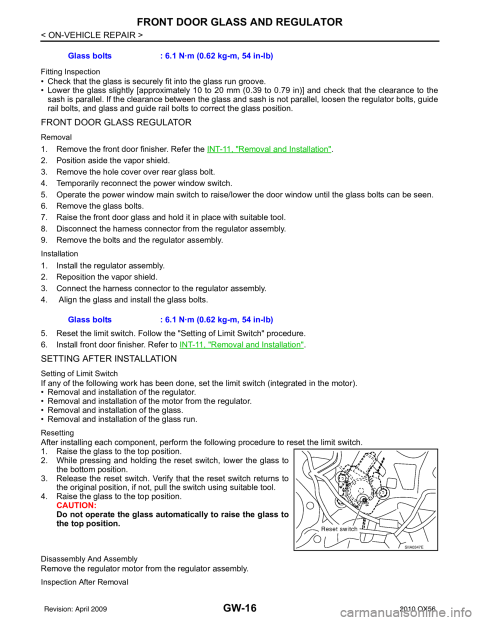
1. Door glass run 2. Door glass3. Front door glass regulator assembly
WIIA0941E
LIIA1687E
Revision: April 20092010 QX56
Page 2287 of 4210

GW-16
< ON-VEHICLE REPAIR >
FRONT DOOR GLASS AND REGULATOR
Fitting Inspection
• Check that the glass is securely fit into the glass run groove.
• Lower the glass slightly [approximately 10 to 20 mm (0.39 to 0.79 in)] and check that the clearance to the
sash is parallel. If the clearance between the glass and sash is not parallel, loosen the regulator bolts, guide
rail bolts, and glass and guide rail bolts to correct the glass position.
FRONT DOOR GLASS REGULATOR
Removal
1. Remove the front door finisher. Refer the INT-11, "Removal and Installation".
2. Position aside the vapor shield.
3. Remove the hole cover over rear glass bolt.
4. Temporarily reconnect the power window switch.
5. Operate the power window main switch to raise/ lower the door window until the glass bolts can be seen.
6. Remove the glass bolts.
7. Raise the front door glass and hold it in place with suitable tool.
8. Disconnect the harness connector fr om the regulator assembly.
9. Remove the bolts and the regulator assembly.
Installation
1. Install the regulator assembly.
2. Reposition the vapor shield.
3. Connect the harness connector to the regulator assembly.
4. Align the glass and install the glass bolts.
5. Reset the limit switch. Follow the "Setting of Limit Switch" procedure.
6. Install front door finisher. Refer to INT-11, "
Removal and Installation".
SETTING AFTER INSTALLATION
Setting of Limit Switch
If any of the following work has been done, set the limit switch (integrated in the motor).
• Removal and installation of the regulator.
• Removal and installation of the motor from the regulator.
• Removal and installation of the glass.
• Removal and installation of the glass run.
Resetting
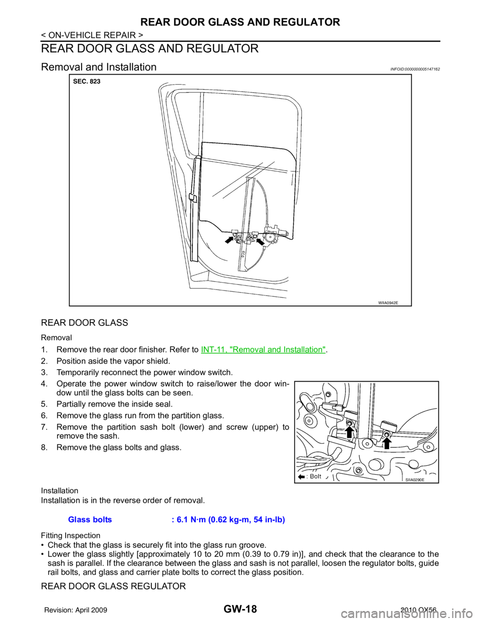
After installing each component, perform the following procedure to reset the limit switch.
1. Raise the glass to the top position.
2. While pressing and holding the reset switch, lower the glass to
the bottom position.
3. Release the reset switch. Verify that the reset switch returns to the original position, if not, pu ll the switch using suitable tool.
4. Raise the glass to the top position. CAUTION:
Do not operate the glass automatically to raise the glass to
the top position.
Disassembly And Assembly
Remove the regulator motor from the regulator assembly.
Inspection After Removal
Glass bolts : 6.1 N·m (0.62 kg-m, 54 in-lb)
Glass bolts : 6.1 N·m (0.62 kg-m, 54 in-lb)
SIIA0347E
Revision: April 20092010 QX56
Page 2289 of 4210

GW-18
< ON-VEHICLE REPAIR >
REAR DOOR GLASS AND REGULATOR
REAR DOOR GLASS AND REGULATOR
Removal and InstallationINFOID:0000000005147162
REAR DOOR GLASS
Removal
1. Remove the rear door finisher. Refer to INT-11, "Removal and Installation".
2. Position aside the vapor shield.
3. Temporarily reconnect the power window switch.
4. Operate the power window switch to raise/lower the door win- dow until the glass bolts can be seen.
5. Partially remove the inside seal.
6. Remove the glass run from the partition glass.
7. Remove the partition sash bolt (lower) and screw (upper) to remove the sash.
8. Remove the glass bolts and glass.
Installation
Installation is in the reverse order of removal.
Fitting Inspection
• Check that the glass is securely fit into the glass run groove.
• Lower the glass slightly [approximately 10 to 20 mm (0.39 to 0.79 in)], and check that the clearance to the
sash is parallel. If the clearance between the glass and sash is not parallel, loosen the regulator bolts, guide
rail bolts, and glass and carrier plate bolts to correct the glass position.
REAR DOOR GLASS REGULATOR
WIIA0942E
SIIA0290E
Glass bolts : 6.1 N·m (0.62 kg-m, 54 in-lb)
Revision: April 20092010 QX56
Page 2290 of 4210

REAR DOOR GLASS AND REGULATORGW-19
< ON-VEHICLE REPAIR >
C
DE
F
G H
I
J
L
M A
B
GW
N
O P
Removal
1. Remove the rear door finisher. Refer to
INT-11, "Removal and Installation".
2. Position aside the vapor shield.
3. Temporarily reconnect the power window switch.
4. Operate the power window switch to raise/lower the door win- dow until the glass bolts can be seen.
5. Remove the inside seal.
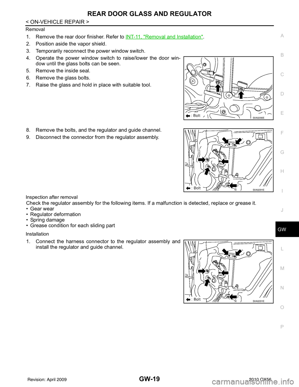
6. Remove the glass bolts.
7. Raise the glass and hold in place with suitable tool.
8. Remove the bolts, and the regulator and guide channel.
9. Disconnect the connector from the regulator assembly.
Inspection after removal
Check the regulator assembly for the following items. If a malfunction is detected, replace or grease it.
• Gear wear
• Regulator deformation
• Spring damage
• Grease condition for each sliding part
Installation
1. Connect the harness connector to the regulator assembly and install the regulator and guide channel.
SIIA0290E
SIIA0291E
SIIA0291E
Revision: April 20092010 QX56
Page 2292 of 4210

SIDE WINDOW GLASSGW-21
< ON-VEHICLE REPAIR >
C
DE
F
G H
I
J
L
M A
B
GW
N
O P
SIDE WINDOW GLASS
Removal and InstallationINFOID:0000000005147163
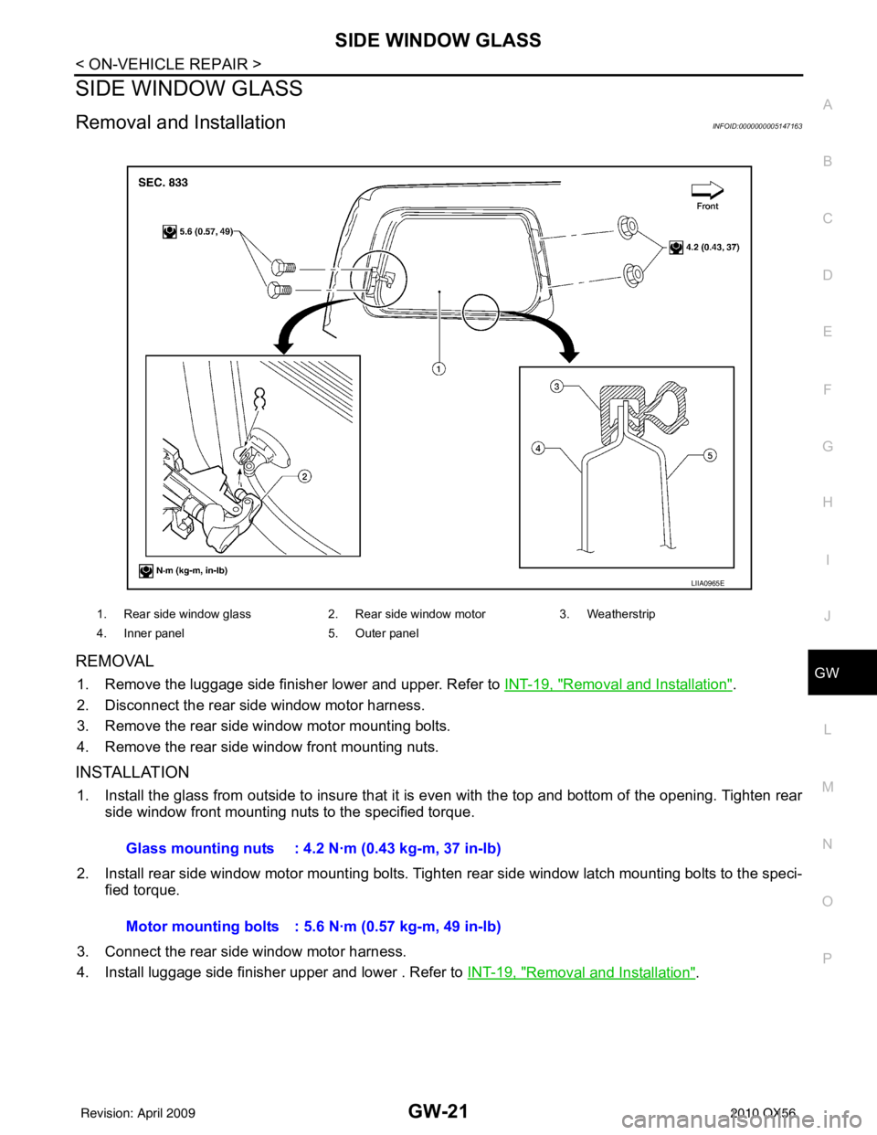
REMOVAL
1. Remove the luggage side finisher lower and upper. Refer to INT-19, "Removal and Installation".
2. Disconnect the rear side window motor harness.
3. Remove the rear side window motor mounting bolts.
4. Remove the rear side window front mounting nuts.
INSTALLATION
1. Install the glass from outside to insure that it is even with the top and bottom of the opening. Tighten rear side window front mounting nuts to the specified torque.
2. Install rear side window motor mounting bolts. Tighten rear side window latch mounting bolts to the speci-
fied torque.
3. Connect the rear side window motor harness.
4. Install luggage side finisher upper and lower . Refer to INT-19, "
Removal and Installation".
1. Rear side window glass2. Rear side window motor3. Weatherstrip
4. Inner panel 5. Outer panel
LIIA0965E
Glass mounting nuts : 4.2 N·m (0.43 kg-m, 37 in-lb)
Motor mounting bolts : 5.6 N·m (0.57 kg-m, 49 in-lb)
Revision: April 20092010 QX56
Page 2316 of 4210

HA-24
< ON-VEHICLE MAINTENANCE >
FLUORESCENT LEAK DETECTOR
FLUORESCENT LEAK DETECTOR
Checking of Refrigerant LeaksINFOID:0000000005147647
PRELIMINARY CHECK
Perform a visual inspection of all refrigeration parts, fittings, hoses and components for signs of A/C oil leak-
age, damage, and corrosion. Any A/C oil leakage may indicate an area of refrigerant leakage. Allow extra
inspection time in these areas when using either an el ectronic refrigerant leak detector (J-41995) or fluores-
cent dye leak detector (J-42220).
If any dye is observed using a fluorescent dye leak detector (J-42220), confirm the leak using a electronic
refrigerant leak detector (J-41995). It is possible that the dye is from a prior leak that was repaired and not
properly cleaned.
When searching for leaks, do not stop when one leak is found but continue to check for additional leaks at all
system components and connections.
When searching for refrigerant leaks using an electronic refrigerant leak detector (J-41995), move the probe
along the suspected leak area at 25 - 50 mm (1 - 2 in) per second and no further than 6 mm (1/4 in) from the
component.
CAUTION:
Moving the electronic refrigerant l eak detector probe slower and closer to the suspected leak area will
improve the chances of finding a leak.
Checking System for L eaks Using the Fluorescent Dye Leak DetectorINFOID:0000000005147648
1. Check the A/C system for leaks using the fluorescent dye leak detector and safety goggles (J-42220) in a
low sunlight area (area without windows preferable). Il luminate all components, fittings and lines. The dye
will appear as a bright green/yellow area at the point of leakage. Fluorescent dye observed at the evapo-
rator drain opening indicates an evaporator core asse mbly leak (tubes, core or expansion valve).
2. If the suspected area is difficult to see, use an adjustable mirror or wipe the area with a clean shop rag or cloth, then inspect the shop rag or cloth with the fl uorescent dye leak detector (J-42220) for dye residue.
3. After the leak is repaired, remove any residual dye using refrigerant dye cleaner (J-43872) to prevent
future misdiagnosis.
4. Perform a system performance check and then verify t he leak repair using a electronic refrigerant leak
detector (J-41995).
NOTE:
• Other gases in the work area or substances on the A/C components, for example, anti-freeze, wind-
shield washer fluid, solvents and oils, may falsely tri gger the leak detector. Make sure the surfaces to be
checked are clean.
• Clean with a dry cloth or blow off with shop air.
• Do not allow the sensor tip of the electronic refri gerant leak detector (J-41995) to contact with any sub-
stance. This can also cause false readings and may damage the detector.
Dye InjectionINFOID:0000000005147649
NOTE:
This procedure is only necessary when recharging the system or when the compressor has seized and must
be replaced.
1. Check the A/C system static (at rest) pressure . Pressure must be at least 345 kPa (3.52 kg/cm
2 , 50 psi).
2. Pour one bottle 7.4 cc (1/4 ounce) of the HFC-134a (R -134a) fluorescent leak detection dye (J-41447) into
the HFC-134a (R-134a) dye injector (J-41459).
CAUTION:
If repairing the A/C system or replacing a co mponent, pour the HFC-134a (R-134a) fluorescent leak
detection dye (J-41447) directly into the open system connection and proceed with the service
procedures.
3. Connect the refrigerant dye injector (J-41459) to the low-pressure service valve.
4. Start the engine and switch the A/C system ON.
5. When the A/C system is operating (compressor running), inject one bottle 7.4 cc (1/4 ounce) of HFC-134a (R-134a) fluorescent leak detection dye (J-41447) through the low-pressure service valve using HFC-
134a (R-134a) dye injector (J-41459). Refer to the manufacturer's operating instructions.
Revision: April 20092010 QX56