2010 INFINITI QX56 Ignition switch
[x] Cancel search: Ignition switchPage 2998 of 4210
POWER SUPPLY AND GROUND CIRCUITPWC-13
< COMPONENT DIAGNOSIS >
C
DE
F
G H
I
J
L
M A
B
PWC
N
O P
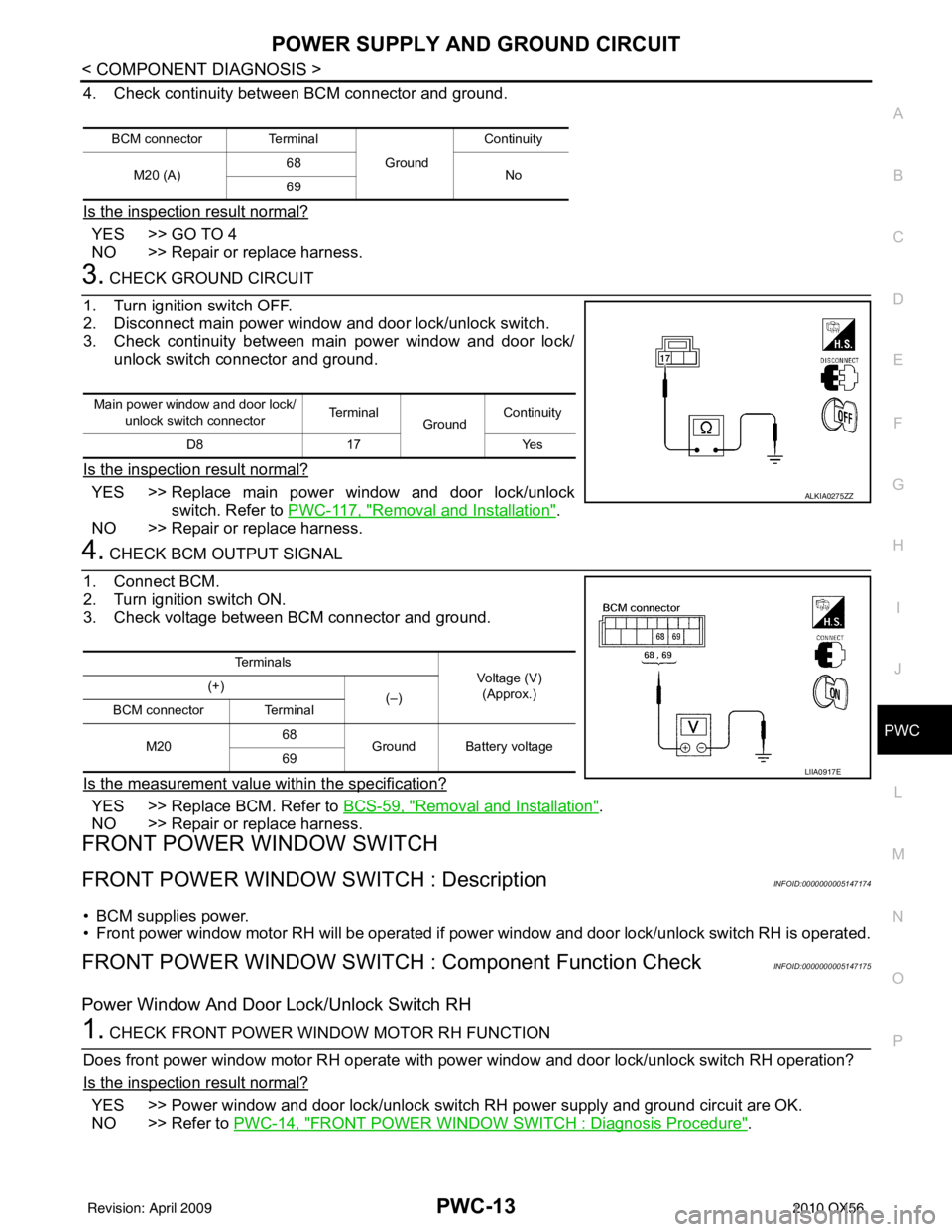
4. Check continuity between BCM connector and ground.
Is the inspection result normal?
YES >> GO TO 4
NO >> Repair or replace harness.
3. CHECK GROUND CIRCUIT
1. Turn ignition switch OFF.
2. Disconnect main power window and door lock/unlock switch.
3. Check continuity between main power window and door lock/ unlock switch connector and ground.
Is the inspection result normal?
YES >> Replace main power window and door lock/unlock switch. Refer to PWC-117, "
Removal and Installation".
NO >> Repair or replace harness.
4. CHECK BCM OUTPUT SIGNAL
1. Connect BCM.
2. Turn ignition switch ON.
3. Check voltage between BCM connector and ground.
Is the measurement value within the specification?
YES >> Replace BCM. Refer to BCS-59, "Removal and Installation".
NO >> Repair or replace harness.
FRONT POWER WINDOW SWITCH
FRONT POWER WINDOW SWITCH : DescriptionINFOID:0000000005147174
• BCM supplies power.
• Front power window motor RH will be operated if power window and door lock/unlock switch RH is operated.
FRONT POWER WINDOW SWITCH : Component Function CheckINFOID:0000000005147175
Power Window And Door Lock/Unlock Switch RH
1. CHECK FRONT POWER WINDOW MOTOR RH FUNCTION
Does front power window motor RH operate with power window and door lock/unlock switch RH operation?
Is the inspection result normal?
YES >> Power window and door lock/unlock switch RH power supply and ground circuit are OK.
NO >> Refer to PWC-14, "
FRONT POWER WINDOW SWITCH : Diagnosis Procedure".
BCM connector Terminal
GroundContinuity
M20 (A) 68
No
69
Main power window and door lock/
unlock switch connector Te r m i n a l
GroundContinuity
D8 17 Yes
ALKIA0275ZZ
Te r m i n a l s
Voltage (V)
(Approx.)
(+)
(–)
BCM connector Terminal
M20 68
Ground Battery voltage
69
LIIA0917E
Revision: April 20092010 QX56
Page 2999 of 4210
PWC-14
< COMPONENT DIAGNOSIS >
POWER SUPPLY AND GROUND CIRCUIT
FRONT POWER WINDOW SWIT CH : Diagnosis Procedure
INFOID:0000000005147176
Regarding Wiring Diagram information, refer to PWC-68, "Wiring Diagram".
1. CHECK POWER SUPPLY CIRCUIT
1. Turn ignition switch ON.
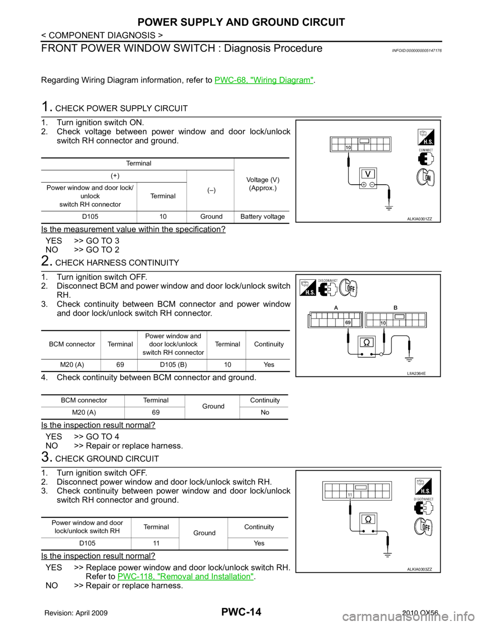
2. Check voltage between power window and door lock/unlock switch RH connector and ground.
Is the measurement value within the specification?
YES >> GO TO 3
NO >> GO TO 2
2. CHECK HARNESS CONTINUITY
1. Turn ignition switch OFF.
2. Disconnect BCM and power window and door lock/unlock switch RH.
3. Check continuity between BCM connector and power window and door lock/unlock switch RH connector.
4. Check continuity between BCM connector and ground.
Is the inspection result normal?
YES >> GO TO 4
NO >> Repair or replace harness.
3. CHECK GROUND CIRCUIT
1. Turn ignition switch OFF.
2. Disconnect power window and door lock/unlock switch RH.
3. Check continuity between power window and door lock/unlock switch RH connector and ground.
Is the inspection result normal?
YES >> Replace power window and door lock/unlock switch RH. Refer to PWC-118, "
Removal and Installation".
NO >> Repair or replace harness.
Te r m i n a l
Voltage (V)(Approx.)
(+)
(–)
Power window and door lock/
unlock
switch RH connector Te r m i n a l
D105 10Ground Battery voltage
ALKIA0301ZZ
BCM connector Terminal Power window and
door lock/unlock
switch RH connector Terminal Continuity
M20 (A) 69 D105 (B)10 Yes
BCM connector Terminal
GroundContinuity
M20 (A) 69 No
LIIA2364E
Power window and door
lock/unlock switch RH Te r m i n a l
Ground Continuity
D105 11 Yes
ALKIA0303ZZ
Revision: April 20092010 QX56
Page 3000 of 4210

POWER SUPPLY AND GROUND CIRCUITPWC-15
< COMPONENT DIAGNOSIS >
C
DE
F
G H
I
J
L
M A
B
PWC
N
O P
4. CHECK BCM OUTPUT SIGNAL
1. Connect BCM.
2. Turn ignition switch ON.
3. Check voltage between BCM connector and ground.
Is the measurement value within the specification?
YES >> Replace power window and door lock/unlock switch RH.
Refer to PWC-118, "
Removal and Installation".
NO >> Replace BCM. Refer to BCS-59, "
Removal and Installation".
REAR POWER WINDOW SWITCH
REAR POWER WINDOW SWITCH : DescriptionINFOID:0000000005147177
• BCM supplies power.
• Rear power window motor will be operated if rear power window switch is operated. Rear power window\
switch.
REAR POWER WINDOW SWITCH : Component Function CheckINFOID:0000000005147178
Rear Power Window Switch
1. CHECK REAR POWER WINDOW MOTOR FUNCTION
Does rear power window motor operate with rear power window switch operation?
Is the inspection result normal?
YES >> Rear power window switch power supply and ground circuit are OK.
NO >> Refer to PWC-15, "
REAR POWER WINDOW SWITCH : Diagnosis Procedure".
REAR POWER WINDOW SWITCH : Diagnosis ProcedureINFOID:0000000005147179
Regarding Wiring Diagram information, refer to PWC-53, "Wiring Diagram".
1. CHECK POWER WINDOW POWER SUPPLY CIRCUIT
1. Turn ignition switch OFF.
2. Disconnect rear power window switch LH or RH.
3. Turn ignition switch ON.
4. Check voltage between rear power window switch LH or RH connector D203 (LH), D303 (RH) terminals 2, 3 and ground.
Is the inspection result normal?
YES >> GO TO 2
NO >> Repair or replace harness.
2. CHECK POWER WINDOW GROUND CIRCUIT
Te r m i n a l s Voltage (V)
(Approx.)
(+)
(-)
BCM connector Terminal
M20 69Ground Ba ttery voltage
WIIA0508E
2 - Ground : Battery voltage
3 - Ground : Battery voltage
LIIA1348E
Revision: April 20092010 QX56
Page 3001 of 4210
PWC-16
< COMPONENT DIAGNOSIS >
POWER SUPPLY AND GROUND CIRCUIT
1. Turn ignition switch OFF.
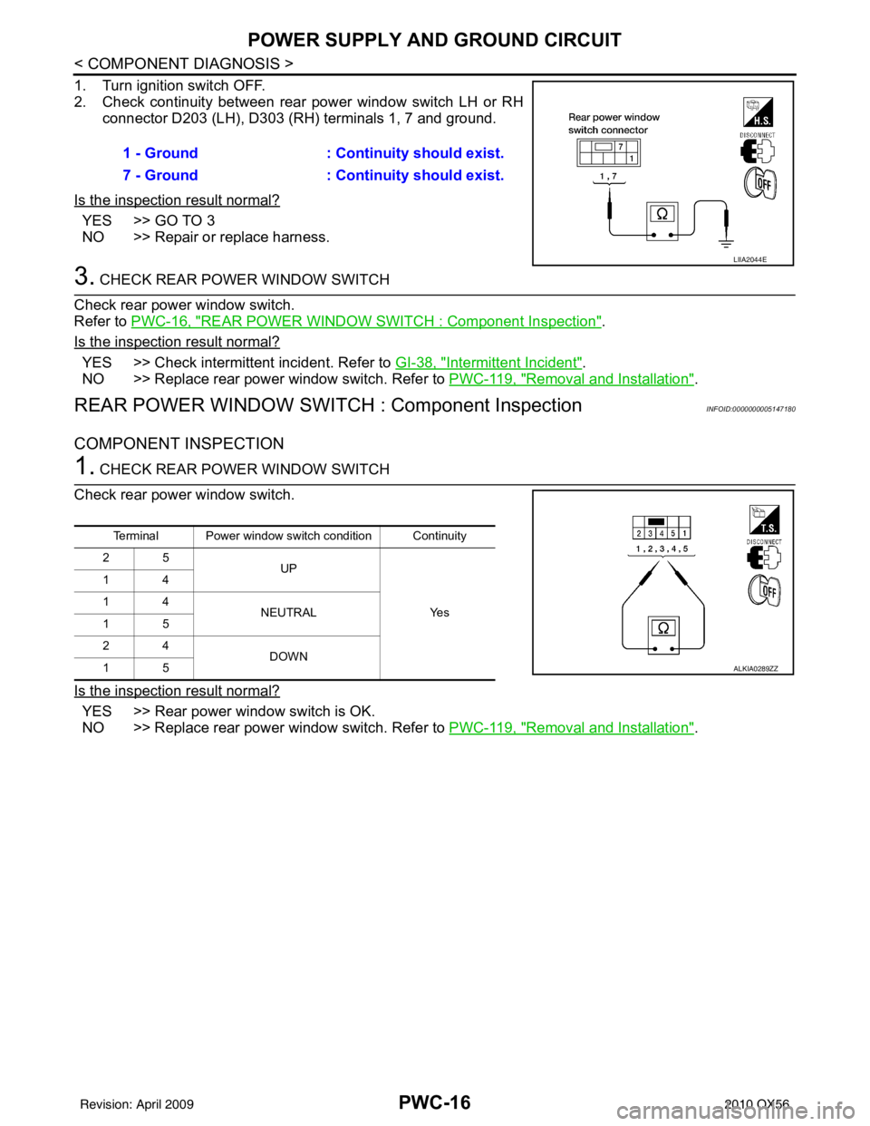
2. Check continuity between rear power window switch LH or RHconnector D203 (LH), D303 (RH) terminals 1, 7 and ground.
Is the inspection result normal?
YES >> GO TO 3
NO >> Repair or replace harness.
3. CHECK REAR POWER WINDOW SWITCH
Check rear power window switch.
Refer to PWC-16, "
REAR POWER WINDOW SWITCH : Component Inspection".
Is the inspection result normal?
YES >> Check intermittent incident. Refer to GI-38, "Intermittent Incident".
NO >> Replace rear power window switch. Refer to PWC-119, "
Removal and Installation".
REAR POWER WINDOW SWITCH : Component InspectionINFOID:0000000005147180
COMPONENT INSPECTION
1. CHECK REAR POWER WINDOW SWITCH
Check rear power window switch.
Is the inspection result normal?
YES >> Rear power window switch is OK.
NO >> Replace rear power window switch. Refer to PWC-119, "
Removal and Installation".
1 - Ground
: Continuity should exist.
7 - Ground : Continuity should exist.
LIIA2044E
Terminal Power window switch condition Continuity
25 UP
Ye s
14
14
NEUTRAL
15
24 DOWN
15
ALKIA0289ZZ
Revision: April 20092010 QX56
Page 3002 of 4210
POWER WINDOW MOTORPWC-17
< COMPONENT DIAGNOSIS >
C
DE
F
G H
I
J
L
M A
B
PWC
N
O P
POWER WINDOW MOTOR
DRIVER SIDE
DRIVER SIDE : DescriptionINFOID:0000000005147181
Door glass moves UP/DOWN by receiving the signal from power window main switch.
DRIVER SIDE : Componen t Function CheckINFOID:0000000005147182
1. CHECK POWER WINDOW MOTOR CIRCUIT
Does front power window motor LH operate with operating main power window and door lock/unlock switch?
Is the inspection result normal?
YES >> Front power window motor LH is OK.
NO >> Refer to PWC-17, "
DRIVER SIDE : Diagnosis Procedure".
DRIVER SIDE : Diag nosis ProcedureINFOID:0000000005147183
Regarding Wiring Diagram information, refer to PWC-53, "Wiring Diagram".
1. CHECK MAIN POWER WINDOW AND DOOR LOCK/UNLOCK SWITCH OUTPUT SIGNAL
1. Disconnect front power window motor LH.
2. Turn ignition switch ON.
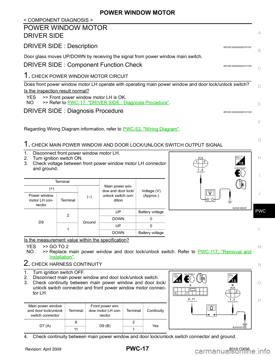
3. Check voltage between front power window motor LH connector and ground.
Is the measurement value within the specification?
YES >> GO TO 2
NO >> Replace main power window and door lock/unlock switch. Refer to PWC-117, "
Removal and
Installation".
2. CHECK HARNESS CONTINUITY
1. Turn ignition switch OFF.
2. Disconnect main power window and door lock/unlock switch.
3. Check continuity between main power window and door lock/ unlock switch connector and front power window motor connec-
tor LH.
4. Check continuity between main power window and door lock/unlock switch connector and ground.
Te r m i n a l Main power win-
dow and door lock/
unlock switch con- dition Voltage (V)
(Approx.)
(+)
(–)
Power window
motor LH con- nector Te r m i n a l
D9 2
Ground UP Battery voltage
DOWN 0
1 UP
0
DOWN Battery voltage
ALKIA1302ZZ
Main power window
and door lock/unlock switch connector Te r m i n a lFront power win-
dow motor LH con- nector Terminal Continuity
D7 (A) 8
D9 (B) 2
Ye s
11 1
ALKIA1019ZZ
Revision: April 20092010 QX56
Page 3004 of 4210
POWER WINDOW MOTORPWC-19
< COMPONENT DIAGNOSIS >
C
DE
F
G H
I
J
L
M A
B
PWC
N
O P
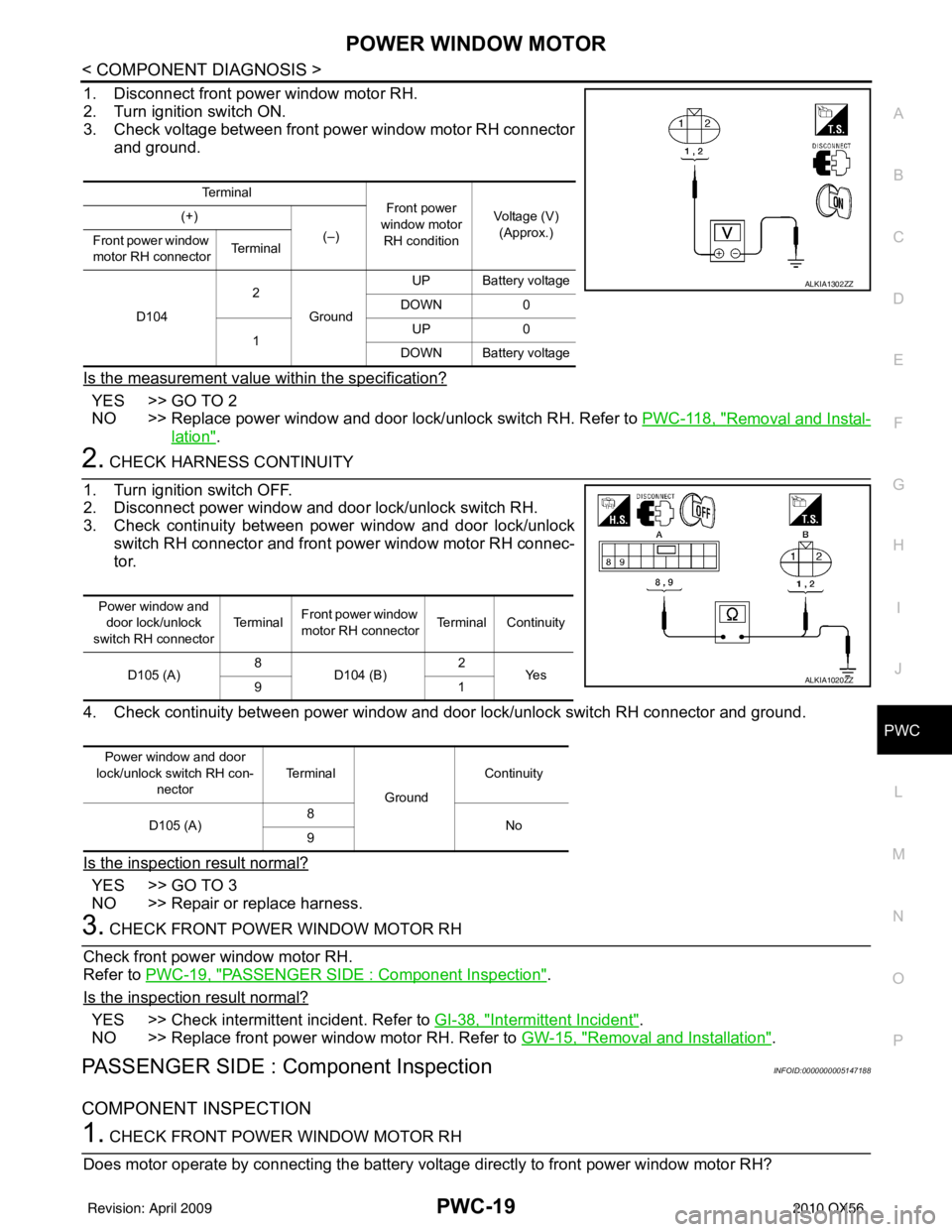
1. Disconnect front power window motor RH.
2. Turn ignition switch ON.
3. Check voltage between front power window motor RH connector and ground.
Is the measurement value within the specification?
YES >> GO TO 2
NO >> Replace power window and door lock/unlock switch RH. Refer to PWC-118, "
Removal and Instal-
lation".
2. CHECK HARNESS CONTINUITY
1. Turn ignition switch OFF.
2. Disconnect power window and door lock/unlock switch RH.
3. Check continuity between power window and door lock/unlock switch RH connector and front power window motor RH connec-
tor.
4. Check continuity between power window and door lock/unlock switch RH connector and ground.
Is the inspection result normal?
YES >> GO TO 3
NO >> Repair or replace harness.
3. CHECK FRONT POWER WINDOW MOTOR RH
Check front power window motor RH.
Refer to PWC-19, "
PASSENGER SIDE : Component Inspection".
Is the inspection result normal?
YES >> Check intermittent incident. Refer to GI-38, "Intermittent Incident".
NO >> Replace front power window motor RH. Refer to GW-15, "
Removal and Installation".
PASSENGER SIDE : Component InspectionINFOID:0000000005147188
COMPONENT INSPECTION
1. CHECK FRONT POWER WINDOW MOTOR RH
Does motor operate by connecting the battery voltage directly to front power window motor RH?
Te r m i n a l Front power
window motor RH condition Voltage (V)
(Approx.)
(+)
(–)
Front power window
motor RH connector Te r m i n a l
D104 2
Ground UP Battery voltage
DOWN 0
1 UP
0
DOWN Battery voltage
ALKIA1302ZZ
Power window and door lock/unlock
switch RH connector Te r m i n a l
Front power window
motor RH connector
Terminal Continuity
D105 (A) 8
D104 (B) 2
Ye s
91
Power window and door
lock/unlock switch RH con- nector Terminal
Ground Continuity
D105 (A) 8
No
9
ALKIA1020ZZ
Revision: April 20092010 QX56
Page 3005 of 4210
PWC-20
< COMPONENT DIAGNOSIS >
POWER WINDOW MOTOR
Is the inspection result normal?
YES >> Front power window motor RH is OK.
NO >> Replace front power window motor RH. Refer to GW-15, "
Removal and Installation".
REAR LH
REAR LH : DescriptionINFOID:0000000005147189
Door glass moves UP/DOWN by receiving the signal from power window main switch or rear power window
switch LH.
REAR LH : Componen t Function CheckINFOID:0000000005147190
1. CHECK REAR POWER WINDOW MOTOR LH CIRCUIT
Does rear power window motor LH operate with main power window and door lock/unlock switch or rear
power window switch LH?
Is the inspection result normal?
YES >> Rear power window motor LH is OK.
NO >> Refer to PWC-20, "
REAR LH : Diagnosis Procedure".
REAR LH : Diagnosis ProcedureINFOID:0000000005147191
Regarding Wiring Diagram information, refer to PWC-53, "Wiring Diagram".
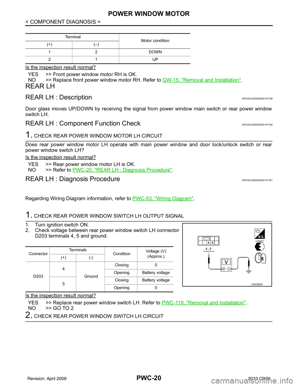
1. CHECK REAR POWER WINDOW SWITCH LH OUTPUT SIGNAL
1. Turn ignition switch ON.
2. Check voltage between rear power window switch LH connector D203 terminals 4, 5 and ground.
Is the inspection result normal?
YES >> Replace rear power window switch LH. Refer to PWC-119, "Removal and Installation".
NO >> GO TO 2
2. CHECK REAR POWER WINDOW SWITCH LH CIRCUIT
Te r m i n a l Motor condition
(+) (–)
12 D OW N
21 U P
ConnectorTe r m i n a l s
ConditionVoltage (V)
(Approx.)
(+) (-)
D203 4
Ground Closing
0
Opening Battery voltage
5 Closing Battery voltage
Opening 0
LIIA2365E
Revision: April 20092010 QX56
Page 3006 of 4210
POWER WINDOW MOTORPWC-21
< COMPONENT DIAGNOSIS >
C
DE
F
G H
I
J
L
M A
B
PWC
N
O P
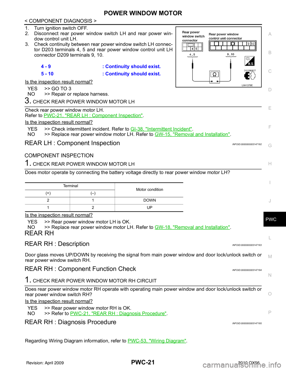
1. Turn ignition switch OFF.
2. Disconnect rear power window switch LH and rear power win- dow control unit LH.
3. Check continuity between rear power window switch LH connec- tor D203 terminals 4, 5 and rear power window control unit LH
connector D209 terminals 9, 10.
Is the inspection result normal?
YES >> GO TO 3
NO >> Repair or replace harness.
3. CHECK REAR POWER WINDOW MOTOR LH
Check rear power window motor LH.
Refer to PWC-21, "
REAR LH : Component Inspection".
Is the inspection result normal?
YES >> Check intermittent incident. Refer to GI-38, "Intermittent Incident".
NO >> Replace rear power window motor LH. Refer to GW-15, "
Removal and Installation".
REAR LH : Component InspectionINFOID:0000000005147192
COMPONENT INSPECTION
1. CHECK REAR POWER WINDOW MOTOR LH
Does motor operate by connecting the battery voltage directly to rear power window motor LH?
Is the inspection result normal?
YES >> Rear power window motor LH is OK.
NO >> Replace rear power window motor LH. Refer to GW-18, "
Removal and Installation".
REAR RH
REAR RH : DescriptionINFOID:0000000005147193
Door glass moves UP/DOWN by receiving the signal from main power window and door lock/unlock switch or
rear power window switch RH.
REAR RH : Component Function CheckINFOID:0000000005147194
1. CHECK REAR POWER WINDOW MOTOR RH CIRCUIT
Does rear power window motor RH operate with operat ing main power window and door lock/unlock switch or
rear power window switch RH?
Is the inspection result normal?
YES >> Rear power window motor RH is OK.
NO >> Refer to PWC-21, "
REAR RH : Diagnosis Procedure".
REAR RH : Diagnosis ProcedureINFOID:0000000005147195
Regarding Wiring Diagram information, refer to PWC-53, "Wiring Diagram".
4 - 9
: Continuity should exist.
5 - 10 : Continuity should exist.
LIIA1379E
Te r m i n a l
Motor condition
(+) (–)
21 D OW N
12 U P
Revision: April 20092010 QX56